01/25/2022 1,737 Alarms
Author: Victor
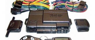
The Starline A4 car alarm is an anti-theft system with two-way communication, which incorporates a modular principle for constructing a vehicle security system. Despite the fact that this model is powered by a voltage in the range of 9-18 volts, its installation is allowed only on passenger cars.
[Hide]
Car security system with two-way communication Twage…
Twage, A4, a2, a1
- Image
- Text
Car security system
with two-way communication
Twage
— A4, A2, A1
I N S T R U C T I O N
P O E C S P L U A T I O N S I U S T A N O V K E
Contents Car Alarm Operating Instructions Set…
Page 3
- Image
- Text
3
Twage A4, A2, A1
Content
Instructions for use of car alarms Alarm components……………………………………………………………………………………. 4 Technical characteristics of the alarm system……………………………………………………… 5 Signaling capabilities ………………………………………………………………………………… … 6 Alarm control key fobs ……………………………………………………… 8 Key fob batteries and their replacement ………………………………………… ………. 9 Purpose of the key fob buttons ………………………………………………………………………………… 12 Duration of pressing the key fob buttons ……………………………………………………… 13 Alarm control………………………………………………………………….. 14 Self-diagnosis when turning on the security mode…………………………………. 19 Self-diagnosis when the security mode is turned off……………………………….. 19 Protective and anti-theft functions of the alarm system………………………………. 20 Alarm service functions ……………………………………………………….. 25 LED indication of alarm status …………………………………… 32 Recording key fob codes … ………………………………………………………………………………… 32 Setting up the built-in shock sensor……………………………………………………………… ….. 33 Personal emergency alarm deactivation code ……………………… 34 Alarm operation with the StarLine 02 engine starting module ……………… 35 Alarm operation with the security search GSM/GPS module ……………. 35 Programming functions and parameters of alarm operation…………….. 36
Instructions for installing a car alarm Recommendations for the placement and installation of components…………………………. 38 Recommendations for laying and connecting wires ………………………….. 39 Recommendations for connecting individual alarm components …… 40 Alarm connection diagram ………………………………………………………… ………. 45 Warranty obligations………………………………………………………………. 46
How to install?
All alarm elements must be installed discreetly. Only open installation of the transceiver and LED in the car interior is allowed.
System installation algorithm:
- All components of the alarm system are assembled and connected separately, without installation on the car. You need to connect the complex to the battery and check its operation. If one of the alarm elements is faulty, the user will be able to find out about it in advance.
- The voltage in the vehicle's on-board network is turned off. To do this, open the engine compartment and disconnect the terminal clamp from the negative battery output. In this case, the ignition, as well as all electrical equipment, must already be turned off.
- The siren is located under the hood of the vehicle, in the most hidden place. It is installed with the horn facing down to prevent moisture from accumulating inside the device. The wires are routed into the cabin to the control unit; connections should not be made under the hood. Installation of the siren is not allowed in places exposed to high temperatures and other factors. The wires and the device itself should not be accessible from under the bottom.
- A microprocessor unit is installed in the car interior. It is recommended to place it in a free compartment behind the instrument panel, audio system or glove compartment. The first option is the most acceptable, since it will ensure the minimum cable length. The module is positioned with the block facing down, this will avoid its damage as a result of moisture getting inside the device and flowing down the conductors. The unit is placed on a flat surface, away from electronic devices and potential sources of interference.
- The shock and sensitivity sensor, as well as additional controllers, are installed inside the car. It is recommended to place them in the central part of the body so that the devices can optimally record any impacts and impacts. The controllers are mounted on a flat metal surface using plastic ties or self-tapping screws.
- The LED indicator and transceiver module are installed inside the car, near the windshield. It is recommended to place the antenna adapter as high as possible, but away from metal objects (at a distance of at least 5 cm). The diode is installed so that its flickering is visible from the street. The surface of the windshield must first be cleaned and degreased to ensure high-quality fastening. The elements are fixed using double-sided tape or glue.
- The button to enter the “Valet” service mode is installed secretly in the cabin. It should be located under the instrument panel and hidden in one of the wiring harnesses. The user must have access to the key while sitting in the driver's seat. Additionally, the button can be wrapped with electrical tape to ensure maximum concealment.
- Limit switches are installed on all doors, trunk and hood. However, they should not be placed in gutters.
- Wires from the devices are pulled to the control unit.
- If installation of an additional autostart module is required, it is installed next to the control unit. Tips for placing these devices are similar - the “device” is placed secretly in a place least exposed to moisture.
Recommendations for laying and connecting wires
Electrical lines must be laid away from sources of potential interference. We are talking about high-voltage cables, distributor and other elements of the ignition system. Do not allow electrical conductors to come into contact with moving body components. The cables are connected with the battery disconnected, and the soldering points must be protected with heat-shrinkable tubing and electrical tape.
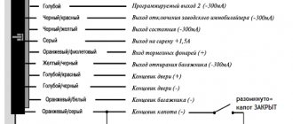
A description of the pins with connection recommendations is given in the table:
| Contact number | Conductor color | Purpose |
| 1 | Red | The +12 volt positive power terminal must be connected directly to the positive side of the battery |
| 2 | Black | “Ground” or grounding must be connected to any bolt installed on the car body |
| 3 | Blue | Negative output of the first additional channel. The maximum load value is 300 mA. It is possible to use a contact to open the tailgate. The connection must be made using a relay with normally closed and open contacts. |
| 4 | Red-black (thin) | Anti-theft system status negative output. The output is used to connect an external blocking relay. The type of its contact elements is programmable by the user. |
| 5 | Purple-orange | Connects to a push-button switch for the handbrake pedal or lever. However, its use is only necessary if the alarm system is equipped with an engine auto-start module. If you do not need to connect to the pedal or handbrake, then the contact is connected to the car body. |
| 6 | Red-blue | Connects to door limit switches that close to +12 volts when unlocked |
| 7 | White-orange | Connects to the “limit switch” of the luggage compartment, which closes to the body when it is opened |
| 8 | Black-green | Must be connected to the contacts of light devices in side optics or turn indicators |
| 9 | Yellow-green | Likewise |
| 10 | Yellow | Must be connected to the ignition switch, the contact where 12 volts appears when activated |
| 11 | Grey | Positive output for connection to a siren, maximum load current is 2 amperes |
| 12 | Black and yellow | Negative contact for connecting a second additional channel. It can be used to control the tailgate lock or activate the courtesy lights. When connecting, it is necessary to use an additional relay with normally closed and open contacts. |
| 13 | Black and blue | Connects to limit switches installed on doors. We are talking about devices that are shorted to ground when the locks are opened. |
| 14 | Gray-orange | Must be connected to the hood “trailer” |
Recommendations for connecting components
Features of connecting individual alarm elements:
- The output of the 4-pin antenna adapter bus must be connected to the corresponding 4-pin connector on the microprocessor module. This block is hidden by a protective cover. A cable is used for connection.
- The output of the additional controller must be connected to the 4-pin connector, which is located next to the main plug.
- The LED indicator must be connected to the small two-pin output on the microprocessor module. It is hidden by a protective cover.
- The key for entering emergency mode is connected to a two-pin connector on the control unit.
- If an additional autostart module is used, then the output from its interface must be connected to a four-pin block. It is located on the microprocessor module and is hidden by a hinged lid. To implement the task, a wire is used, which is included with the device.
Connection diagram
Connection map of the Starline A4 anti-theft system:
1 part of the alarm wiring diagram
Part 2 of the block connection map
Operating and installation instructions Contents Includes…
Page 4
- Image
- Text
4
Operating and installation instructions
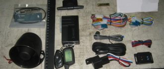
Completeness
Included in the StarLine Twage
A4 includes: 1 main remote control key fob with LCD
indicator (LCD) and two-way communication, 1 additional key fob
remote control without feedback, central unit, 2-level
shock sensor, transceiver module with antenna, LED indicator,
Valet service button, hood button, 30A relay with block, cable kits,
instructions. Included in the StarLine Twage
A2 includes: 1 main remote control key fob with LED
indicators (LED) and two-way communication, 1 additional key fob
remote control without feedback, central unit, 2-level
shock sensor, transceiver module with antenna, LED indicator,
Valet service button, hood button, 30A relay with block, cable kits,
instructions. Included in the StarLine Twage
A1 includes: 2 remote control key fobs without feedback, central unit,
2-level shock sensor, receiving module with antenna, LED
indicator, Valet service button, hood button, 30A relay with block,
cable kits, instructions.
Malfunctions A4
Starline A4 car alarm breakdowns
| Malfunction | There is no response to the key fob |
| Causes | — the batteries in the remote control are low; — the car battery is discharged; — strong radio interference; — the receiver antenna is faulty; — software failure of the central module. |
| Solutions | Dead batteries and batteries must be replaced. A faulty antenna can be repaired at a service center or a new antenna unit can be purchased. If a software failure occurs, the problem can be solved by re-recording the key fob in the Starline a4 memory. |
Technical characteristics Coding of radio control signal…
Page 5
- Image
- Text
5
Twage A4, A2, A1
Specifications
Encoding of the radio control signal …………………………… dynamic Carrier frequency of the radio control signal …………………………… 433.92 MHz Maximum range of the pager ……………………………. 1200 m* Maximum range of key fobs with feedback…………. 600 m* Maximum range of the key fob without feedback……………. 15 m* Operating temperature …………………………………………………………… from –40 to +85 °C DC supply voltage ……………………………………………………… …… 9-18V Current consumed by the alarm in security mode ………….. no more than 20 mA Maximum permissible current at the outputs:
·
siren connection circuits……………………………………………………….. 2A
·
side light connection circuits…………………………………….. 2x7.5A
·
control circuits for electric door lock drives …………………….. 15A
·
circuits of additional control channels…………………………….. 300 mA
·
engine lock relay control circuit…………………………….. 300mA
* The range of key fobs and pagers may be reduced depending
from the location of the transceiver in the car, location
vehicle and user, radio frequency interference, weather conditions,
voltage of the car battery and key fob battery. Car alarms StarLine Twage
permitted for use on site
Russian Federation and comply with the requirements of regulatory documents of the Russian Federation, which
confirmed by a certificate of conformity. Service life of StarLine Twage
, installed by the company -
manufacturer is 5 years, provided that they are installed and
are operated in strict accordance with these instructions.
Starline A8 is the best representative of its series
Photo of the Starline A8 car alarm
Compared to the A4 model, the Starline A8 looks much more preferable. Its main advantage is the presence of auto engine start, which makes using the vehicle much more comfortable. In addition, this system is distinguished by a wide variety of functions and wide possibilities for connecting additional equipment.
Side buttons on the Starline A8 car alarm key fob
StarlineA8 does not have many additional options that newer security systems can boast of, but the functions that it has in its arsenal are enough to protect the car from thieves and carjackers.
Keychain in Starline A8 car alarm case
Since this model is no longer produced by the manufacturer, it is not installed on new cars. Those drivers whose cars are equipped with Starline A8 should remember that each mechanism has a service life, after which the equipment may malfunction, and if possible, replace the A8 with a newer model.
| Video – Keychain Starline A4 |
| Video – Starline A8 car alarm unit |
Car alarm capabilities
Page 6
- Image
- Text
6
Operating and installation instructions
Car alarm capabilities
Protected areas of the car
· Engine – from starting (locking relay) · Doors, hood, trunk – from opening (push-button switches) · Body, windows – from shocks and shocks (two-level shock sensor) · Interior – from penetration (additional two-level sensor) · Ignition – from switching on (ignition switch control input) Parking brake – from off
Car alarm security
· Dynamic control code, protected from selection and interception · Limitation of the number of alarm cycles · Interruption of alarm signals without disabling the security mode · Memorizing the initial alarm state when the power is turned off · Personal emergency shutdown code
Security and anti-theft functions
· 9 independent security zones · Sound and light alarms when security sensors are triggered · Alarm alerts are sent to the key fob with feedback · Programmable output for engine blocking: NO / NC contact type · Programmable immobilizer mode · Two modes for enabling the anti-theft function · Safe Engine blocking in anti-robbery mode Panic mode
Self-diagnosis and indication of operating modes
· Monitoring the condition of the vehicle, operating modes and reasons for triggering
alarm via LED indicator on the dashboard and
indicators on key fobs with feedback Automatic control of security sensors with disabling faulty and
message about this · Sound and light indication of the fact that the alarm has been triggered · LED indication of the serviceability of the door limit switches, hood,
trunk
Reviews from Starline A4 and A8 owners
| Positive | Negative |
| The Starline A8 car alarm, although old, works well. At one time it was malfunctioning, but it turned out that the control unit was located close to the engine and overheated. The guys at the service moved it to another place, and since then (about 2 years) it has been working just fine. | I received a starline a4 along with the purchased car. The previous owner did not have it connected. After fiddling around a bit, I connected it (it’s good that the diagram is on the Internet), but it doesn’t want to work normally. It doesn’t always respond to the key fob the first time, and if you press it several times in a row, all sorts of strange modes are activated, which are then difficult to get rid of. The reception radius is very small, about 5 meters. No further. It is generally impossible to connect autostart, or rather it is possible, but you need a special module, and it costs more than this whole alarm system. The sensor, however, works normally, the siren does not scream for no reason. The rest is complete darkness. Not surprisingly, its former owner turned it off. |
| I've had the A4 for 10 years now. It doesn’t have any false alarms, it’s easy to control from the remote control, the radius is small, but it’s enough for me. I change the batteries about once a year. It withstands both heat and frost well, I am quite pleased with this alarm. | The Starline A8 alarm system has both pros and cons. But there are probably more downsides. The most important thing is that the batteries on the key fob run out quickly and somehow suddenly. At the same time, the second key fob, which is without feedback, also refuses to work. You have to carry a spare set with you so as not to accidentally end up on the street. Autostart does not work satisfactorily. It is simply impossible to turn it on using the button - the car starts and immediately stalls. We turn it on only based on temperature. In general, the alarm works fine, but I don’t recommend buying one; it’s better to choose a newer model. |
| In 2007 I bought a Japanese car. Since cars are apparently not stolen in Japan, there was no warning light on it. I decided to install a Starline A8 car alarm with auto start, and I want to say that it was the right decision. The A8 turned out to be very stable and reliable. The shock sensor is adjusted precisely, never goes off idle, and reacts when needed. In cold weather there are no problems at all, everything opens and closes clearly. Very convenient autostart feature. In winter it's a real lifesaver. I think that the A8 is much better than any newfangled systems that are connected to phones and constantly glitch. I recommend this alarm to everyone! | Installed at a car dealership when purchasing a new car in 2008. At that time, A8 was the coolest alarm and had the best protection. But time passes, and I am increasingly thinking about buying a new one. I'll tell you why. Firstly, its security system is already outdated, and criminals know how to crack the changing code. Secondly, I would like to have more functions, to control it from my phone, for example. This is very convenient, since the range is practically unlimited. In addition, recently the alarm system has started to malfunction periodically, and may fail at the most crucial moment. |
| I bought it on the advice of a friend, he has a starline a8 on Foltz. Really good stuff. It has a lot of functions, like on expensive models, but it costs surprisingly little. There is even auto start, and it works both according to a given time and temperature. For 2 and a half years, no glitches have been found in this signaling system. For the price, the quality is simply amazing! | Terrible alarm. I had one like this on my old Lada. I constantly fought with her, but never overcame her. I simply turned it off, because it was terribly buggy, and the instructions for the Starline A8 car alarm were terribly confusing. Once we went to the forest, set the alarm, and went to pick mushrooms. We arrive in the evening and can’t open it. The key fob does not respond at all. Generally dead. I had to break the glass. Just like that. |
Related link:
Car alarm Scher-Khan Magicar 9.
*Reviews taken from resources: avtobez.com, irecommend.ru, Otzovik
disabling security mode without a key fob...
Page 7
- Image
- Text
7
Twage A4, A2, A1
Service functions
· Switching on/off the security mode without a key fob · Automatic (passive) switching on the security mode · Automatic return to the security mode in case of accidental shutdown · Silent switching on/off the security mode · Switching on the security mode with a delay in activation of door, hood, sensors
trunk · Security mode with the engine running · Security mode with the built-in shock sensor turned off · Possibility of multiple remote protection within 1 cycle
disabling/enabling the shock sensor and additional sensor by level · Remote control of door locks · Control of door locks from the ignition key · Control of door locks by pressing the foot brake pedal · Two-step unlocking of door locks · Two-pulse unlocking of door locks · Possibility of implementing the "comfort" function · Remote turning on/off the Valet service mode · 2 channels for controlling additional vehicle devices · Courteous car interior lighting mode · Car search mode · Remote configuration mode for the built-in shock sensor · Remote programming mode for new and erasing old key fobs · Control of the number of key fobs in the alarm memory · Possibility of online operation resetting programmable functions to factory settings
presets Remote engine start/stop when working with a launch module
StarLine · Engine start mode by timer when working with the StarLine launch module · Special interface for connecting the security search GSM / GPS module · Mode for blocking the operation of key fob buttons · Key fob energy saving mode with feedback · Control of the key fob battery discharge with LCD (in the A4 model) · Fluorescent illumination of the key fob display with LCD (in the A4 model)
Key fob batteries and their replacement Various key fobs use…
Page 9
- Image
- Text
9
Twage A4, A2, A1
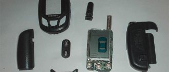
Key fob batteries and their replacement
Different key fobs use different batteries: • a key fob without feedback uses 1 element of type CR2032, 3V • an LED key fob uses 2 batteries of type CR2032, 3V • an LCD key fob uses 1 battery of type “AAA”, 1.5 V. The operating time of the key fob batteries depends on: the frequency of use
key fob, pager frequency, selected mode
alerts depending on the type of battery installed. Element capacities
Commercially available foods may differ several times. The average operating time of batteries can be: • for a key fob without feedback from 9 to 12 months • for a key fob with feedback and LED from 3 to 6 months • for a key fob with feedback and LCD from 6 to 9 months To increase the service life of the element LCD key fob power supply is provided
special energy saving mode that turns on automatically
1 minute after the security mode is turned off. In this mode, consumption
key fob is reduced to a minimum by disconnecting the electrical circuit
receiver Turning on the energy saving mode is accompanied by the disappearance of the icon
from the LCD key fob indicator.
When the battery in the LCD key fob is discharged, an icon is displayed on the indicator
%$7
, which indicates the need to replace it.
Replacement of batteries in key fobs with feedback is carried out
in the following order: 1. Open the cover on the back of the key fob and remove the old battery. 2. Install new batteries, observing polarity. Correct
The position of the battery is indicated on the key fob body under the cover. Close
key fob cover. The batteries in the key fob are replaced without feedback
in the following order: 1. Unscrew the screw on the back of the key fob and open the cover. 2. Remove the old battery and install a new one, observing the polarity.
The correct position of the battery is indicated on the key fob body under
lid. Close the key fob cover and tighten the fixing screw.