01/25/2022 1,484 Alarms
Author: Victor
A special feature of the Starline C9 alarm system is the presence of the SLD Military™ dialogue code, which is resistant to electronic hacking, which is based on the principle of “friend or foe” identification. The individual cryptographic digital key used in this case makes the code of each system unique, which prevents its unauthorized opening by code grabbers or scanners.
[Hide]
Thank you for choosing the Sta…
Car alarms StarLine
- Image
- Text
Thank you for choosing car alarm
StarLine model range with two-way communication and
possibility of remote engine start.
Its appearance became possible thanks to the collective
creativity of Russian development engineers,
American specialists in the field of microelectronics
and Taiwanese high-tech manufacturers
automobile security systems.
So that the car alarm system can most effectively
perform their security and service functions,
We recommend that you trust it to be installed on your car.
professional installers.
We hope that the system will not disappoint your expectations,
will give you confidence in the safety of your car
and will significantly increase its comfort
through a variety of service functions.
Country of origin: Taiwan
DIY installation of StarLine B9
When installing it yourself, you should adhere to a number of general rules, which are the same for the owner of a 1999 Toyota Vitz as for the owner of a UAZ Bukhanka, Lada Kalina or Toyota Chaser. These rules look like this:
- any work is performed only with the battery disconnected;
- the main unit of the anti-theft system must be placed deep in the dashboard to reduce the length of the connection wiring;
- Do not allow moisture to get into the main unit under any circumstances;
- the distance between the heating system and the main unit should be as large as possible, otherwise this will lead to distortion of the temperature sensor readings;
- the antenna is placed on the windshield of the car, maintaining a distance of at least five centimeters from metal parts of the body;
- the siren is placed under the hood so that it is protected as much as possible from both moisture and overheating;
- shock sensors are installed inside the cabin;
- The engine temperature sensor is installed on the crankcase of the latter;
- operation indicators are mounted on the facings of the front pillars or dashboard;
- the service button is installed so that access to it is hassle-free, but the location is inconspicuous;
- for their correct operation, a gap of at least 3 millimeters is left between the limit switches;
- The greatest possible distance should be maintained between signal system wires and potential sources of radio wave interference.
The sequence of steps for installing the device for all vehicle models also looks the same.
- The first step is to install the main unit.
- After which they begin to install the receiver antenna and shock sensors inside the cabin. Having finished this, place a siren and an internal combustion engine temperature sensor under the hood.
- The Valet key is installed and connected, after which limit switches are installed and the relay is connected, as well as the ears to the ignition switch.
- After pinout, all parts are connected to each other using the included wiring harnesses.
- When the installation is complete, test turn on the engine and configure the software parameters, in particular autostart.
The Starline B9 installation map for different car models may differ slightly. There are some peculiarities in connecting the alarm system to the Toyota Corolla Fielder 2004 or Toyota Axio compared to the Matiz or Lada Granta.
Attention
Page 2
- Image
- Text
2
User manual
ATTENTION !
Mandatory safety measures for
use
engine starting functions.
It must be remembered that a car is a vehicle of increased danger. Section 12.8. The traffic rules state: “The driver may leave his seat or leave the vehicle if he has taken the necessary measures to prevent the vehicle from moving spontaneously or being used in the absence of the driver.” Before using the STARLINE Twage C9 car alarm, carefully read the safety precautions for using the remote or automatic engine start function outlined below. 1.
Always park your car in the open, okay
ventilated area. 2.
Always set the vehicle's parking brake
must be in good condition and prevent the vehicle from moving. 3.
When leaving the car, be sure to install the lever
the automatic transmission control is in the “PARK” position, and the manual transmission shift lever is in the neutral position. 4.
If your car has a manual transmission
gears, then before turning on the remote or automatic engine start function, be sure to follow the “soft neutral” procedure for preparing to start the engine. 5.
Never start the car engine without
driver if anyone is in front of or behind the vehicle.
10. How to disable Starline A9
To disable Starline A9 security without a key fob, you must do the following:
- Open the car door with the key. The car alarm will turn on the alarm mode: the siren will scream and the turn signals (dimensions) will flash.
- Turn on the ignition.
- Press the jack button 4 times within 20 seconds. The time is counted from the moment the ignition is turned on.
- Turn off the ignition. If everything is done correctly, the car alarm will be disarmed: the siren will beep 2 times, the emergency lights will blink 2 times.
If you did not have time to complete step 3 within 20 seconds, then turn off the ignition and turn it on again. You again have 20 seconds to press the jack button 4 times.
Attention! If the auto-arming function is activated, then after step 4, be sure to turn on the ignition for 10 seconds. Otherwise, the alarm may be armed again.
Operating instructions Signal specifications…
Page 4
- Image
- Text
4
User manual
Technical characteristics of the alarm system…………………………………………… 5
Components included in the alarm kit………………………………………………………. 6
List of security and service alarm functions …………………………. 8
Alarm control key fobs………………………………………………………. 10
Purpose of key fob buttons …………………………………………………………………………………… 12
Setting up key fob functions………………………………………………………………….. 16
Turning on/off alarm operating modes
using the cursor method……………………………………………. 18
Alarm management
Enabling the security mode…………………………………………………………………………………. 20
Turning off the security mode……………………………………………………………….. 28
Alarm self-diagnosis …………………………………………………………… 32
Security alarm functions………………………………………………………. 36
Anti-theft alarm functions ………………………………………………… 40
Alarm service functions……………………………………………………….. 48
Starting the engine……………………………………………………………………………….. 56
Preparing to start the engine on cars with manual transmission………………. 58
Remote engine start………………………………………………………… 62
Automatic engine starts ……………………………………………………… 64
Personal emergency shutdown code ………………………………………….. 67
Programming security and service alarm functions………….. 68
Summary table of commands executed by the key fob ………………………………….. 71
Key fob batteries and their replacement………………………………………………………….. 74
Warranty obligations………………………………………………………………. 75
Revision No. 1 July 2008
Content
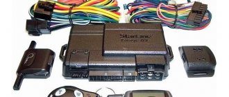
Equipment
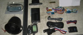
Scope of delivery for this model:
- Service manual. All the nuances regarding the installation and use of the complex are indicated here.
- Main communicator for system management. Equipped with an LCD display and a feedback option.
- Battery for installation in the main console.
- Spare pager. It has a shorter range and does not have two-way communication.
- Microprocessor device, made in a black plastic case.
- Transceiver antenna module.
- The shock regulator belongs to the two-level category.
- A special sticker or double-sided tape is used to secure the antenna adapter.
- Case for main communicator with screen.
- Wire for connecting to the transceiver.
- Electrical circuit for connecting the shock regulator.
- Limit switch. The kit includes one device; it is used for mounting on the hood or trunk door. The first option is more preferable, since this way the alarm can protect the engine compartment from break-ins and theft of units.
- A special button to activate the emergency mode Valet.
- The main wire is equipped with an 18-pin connector.
- An additional set of electrical circuits for connecting all elements of the Starline C9 complex.
- LED status indicator.
Starline C9 package The
Starline C9 package does not include a siren; this device must be purchased separately.
Specifications
Page 5
- Image
- Text
5
Carrier frequency of the radio control signal …………………………433.92 MHz Maximum range of the key fob in transmitter mode ………. 600 m* Maximum range of the key fob in pager mode…………. 1800 m* Maximum range of the key fob without feedback…………….. 15 m* Shock sensor type………………………………………………………. piezoelectric Operating temperature …………………………………………………………… from –40 to +85 °C DC supply voltage …………………………………………………………… .. 9-18V Current consumed by the alarm in security mode…………………. less than 15 mA Maximum permissible current at the outputs: · siren connection circuits ……………………………………………………………… 2A
· connection circuits for direction indicators ………………… ………….. 2x 7.5A
· control circuits for electric drives of door locks …………………………. 20A
· ignition switch circuit……………………………………………………….. 25/30A
· ACC switching circuit……………………………………………………………….. 25/30A
· starter activation circuits………………………………………………………….. 25/30A
· engine blocking circuits……………………………………………………….. 25/30A
· circuits of additional control channels ………………………………… 300 mA Power supply of the key fob with feedback ……… 1.5 V (1 AAA battery) Power supply of the key fob without feedback …….3 V (1 element power supply type CR2032)
*
The range of the key fob and pager may be reduced depending on
on the location of the transceiver, the location of the vehicle and the user, radio frequency interference, weather conditions, car battery voltage and key fob battery voltage. StarLine Twage car alarms are approved for use on the territory of the Russian Federation and comply with all requirements of regulatory documents of the Russian Federation. The service life of StarLine Twage car alarms, established by the manufacturer, is 5 years, provided that they are installed and operated in strict accordance with these instructions.
Specifications
Advantages and disadvantages
Advantages of Starline C9 alarms:
- Extensive functionality that allows you to control not only the anti-theft system, but also some vehicle components.
- Effective protection of nine security zones. For this purpose, it is possible to connect additional controllers. New channels are used to connect each sensor, which eliminates the occurrence of malfunctions in their operation.
- Affordable price.
The main disadvantage of the Starline C9 alarm is the incorrect operation of the communicator at extremely low and high temperatures. According to reviews from owners, the device may malfunction and not respond to button presses.
Security and service alarm functions
Page 8
- Image
- Text
8
User manual
Protected areas of the car and methods of protecting them
· Engine – from starting (conventional relays / digital radio relays StarLIne DRR) · Doors, hood, trunk – from opening (push-button switches) · Parking brake – from switching off (push-button switch) · Body, wheels, windows – from shocks and shocks (two-level shock sensor) Ignition - from switching on (voltage control input on the ignition switch)
Signaling security
· Original dialogue control code, protected from selection and interception by a special algorithm · Memorizing the initial state when the power is turned off and returning to the same state when the power is restored · Limiting the number of alarm cycles from sensors · Interrupting alarms without disabling the security mode
Security and anti-theft alarm functions
· Turn on alarms when sensors are triggered in security mode · Submit alarm signals to the key fob with feedback · Immobilizer mode · Anti-theft mode · Turbo timer mode · Programmable 2-step deactivation of engine locks · Programmable personal emergency shutdown code · Engine lock and its saving when dismantling the alarm
Self-diagnosis and indication of operating modes
· Automatic monitoring of security sensors with disabling faulty ones and reporting this · Indication of alarm status by LED and on the key fob display · Indication of the reasons for alarm activation for 9 security zones · Indication of a faulty zone when the security mode is turned on · Indication of the fact that the alarm has been triggered by sound signals · LED indication of the serviceability of limit switches switches
Security and service functions
alarm
9. Programming Starline A9
To program a number of parameters, including immobilizer and turbo timer modes, you need to configure the Starline A9. How to do it:
- Press the Valet service button 6 times (the ignition must be on).
- After this, turn off the ignition, which should be followed by 6 siren signals and 6 LED flashes - this confirms that you have entered the programming mode.
- Press the Valet button the number of times that corresponds to the serial number of the programmable function. For convenience, every 5th press is accompanied by a long beep.
- Within 10 s, press button 1 or 2: briefly (0.5 s) or long (3 s), depending on how exactly you want to configure the function. The system will notify you of the set value with 1, 2, 3 or 4 short beeps.
- To move on to setting the next function, press the Valet button again. Use keys 1 or 2 to set the required parameters again.
- To exit programming, turn on the ignition. Confirmation will be 5 flashes of dimensions.
Alarm service functions...
Page 9
- Image
- Text
9
Alarm service functions
· Silent security mode · Security mode with the engine running · Silently switching on/off the security mode · Switching on/off the security mode without a key fob · Bypassing the door area for the duration of the interior light extinguishing delay · Automatic return to the security mode in case of accidental shutdown · Remote switching off of sensors by level in security mode · Remote control of the central locking · Control of the central locking from the ignition switch · Two-step unlocking of door locks · Two-pulse unlocking of door locks · Possibility of implementing the “comfort” function · 4 additional control channels · Control of vehicle interior lighting · Panic mode · Car search mode · Valet service mode · Call mode from the car · Protection against accidental pressing of key fob buttons · Sound and vibration modes of key fob operation with feedback · Separate temperature indication in the cabin and under the hood of the car · Energy saving mode of key fob with liquid crystal display · Remote programming of new and erasing lost key fobs · Remote programming of alarm modes and functions · Quick reset of programmable functions to factory settings · Ability to work with StarLine Space and StarLine Messenger modules · Indication of the current time, alarm clock, timer
Engine starting functions
· Remote engine start/stop · Remote extension of running engine · Automatic engine start by temperature, by alarm clock, by timer every 2, 3, 4 hours or 24 hours (daily timer) · Select engine type: petrol/diesel · Select transmission type : automatic / manual · Monitoring of engine operation using signals from a tachometer, generator or on-board network pulsations (noise) · Automatic protection against over-twisting of the starter when starting the engine · Indication of operating time of a running engine on the key fob display
How to install?
In accordance with the installation manual, the security system is installed on a vehicle with the on-board power supply turned off. To do this, you need to disconnect the negative terminal from the battery located under the hood.
Recommendations for placement and installation of components
Features of the location of the components of the anti-theft system:
- The microprocessor module is installed in the most hidden way in the vehicle interior. It is recommended to install the unit behind the instrument cluster to ensure a minimum length of wires when connecting. The module must not be placed near sources of moisture or elevated temperatures. The device is fixed on a flat surface using plastic ties or self-tapping screws.
- The transceiver must be installed on the car window; there should be no metal objects within 50 mm of the device’s mounting location. Otherwise, the range of the alarm will be significantly lower. There is a temperature sensor inside the antenna adapter, so the module should be placed away from heat sources and sunlight.
- The siren is installed under the hood of the car. The bracket that will fix this device is first installed. The siren is placed with the socket down to prevent moisture accumulation inside. After installation, you must make sure that the device and its wires are not accessible from under the bottom of the vehicle.
- The impact controller is located on the partition separating the engine compartment from the passenger compartment. During installation, it is necessary to ensure free access to the adjusting elements of the device. The sensor is fixed using self-tapping screws or double-sided tape.
- The remote temperature controller is fixed on the body of the power unit or any metal surface that is adjacent to it.
- The LED status indicator is located on the instrument panel of the machine, in the most open place. It is important that the operation of the LED can be seen from outside the car.
- The service button is installed in a hidden place in the cabin. The user must have easy access to the device when in the driver's seat.
Connection diagrams
Basic wiring diagrams include:
- general control unit connection map;
- connecting an 18-pin connector.
Photo gallery: general control unit connection map
Wiring diagram for connecting the Starline C9 microprocessor module. Part 1
Wiring diagram for connecting the Starline C9 microprocessor module. Part 2
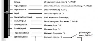
Table: connections of the main 18-pin microprocessor connector
| Contact color | Purpose |
| Black | Negative signal. The contact must be connected to any standard bolt screwed into the car body. It is required to ensure the strongest possible connection. |
| Black wire loop | Designed to select the type of transmission unit. If the car is equipped with an automatic transmission (gearbox), then the loop does not need to be touched; if it is manual, then it is cut. |
| Black-green and yellow-green | It is recommended to connect the contacts for connecting external lighting devices to the light signaling circuit. The wires should be protected with 7.5 amp fuses. |
| Grey | Positive output for connecting a siren |
| Black and blue | Designed for connecting limit switches installed on doors. The contact must close to ground when they open. |
| Red-blue | Push-button door switches. The elements must close to +12 volts when opened. |
| Gray-orange | Hood mounted limit switch |
| White-orange | "Limit switch" of the luggage compartment |
| Black-yellow, red-yellow, yellow-white and blue | Contact elements for connecting negative outputs of 1-4 additional channels, respectively |
| White black | Negative input of the anti-theft system status. The connection must be made using an additional relay. The output should be activated when the protective mode, immobilizer and turbo timer are activated. If the power unit starts while the security system is active, the output should remain active. |
| Pink | Negative contact of the anti-theft system status. Can be used to bypass standard electrical blocking circuits while the motor is running. |
| Black-red | Negative contact of external blocking of the power unit |
| Black-gray | Universal input for monitoring engine operation. The contact can be connected directly to the generator set or tachometer. |
| Purple-orange | Designed to connect a sensor installed on the brake pedal or handbrake |
Photo gallery: 18-pin connector connection diagram
Connection diagram for 18-pin connector. Part 1
Connection diagram for 18-pin connector. Part 2
Alarm control key fobs
Page 10
- Image
- Text
10
User manual
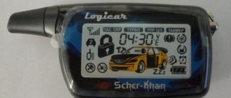
Keychain with feedback Keychain without feedback
The alarm performs its functions either automatically or by signals from the key fob when buttons are pressed. Some of the provided functions and some alarm operating parameters can be changed by programming. The alarm system is equipped with a 3-button control key fob with feedback and a liquid crystal indicator (LCD) and a 3-button control key fob without feedback with LED indication (LED). The purpose of control buttons 1, 2 and 3 of both key fobs is the same. The dynamic control code of the key fobs is protected from selection and interception. When the alarm executes commands sent from any key fob, changes the parameters and operating modes of the alarm or triggers the alarm in security mode, the corresponding information is transmitted to the key fob receiver with feedback and displayed on its indicator with the simultaneous activation of sound and vibration alert signals, and the LED backlight of the indicator is simultaneously turned on. The key fob with feedback uses an original cursor method for selecting some control commands, in which different commands have their own icon, displayed on the key fob indicator. In addition, information about the current time, alarm clock, engine temperature and inside the car is displayed on the key fob indicator with feedback.
Button 1 Button 2 Button 3
Button 1
Button 2
Button 3
Alarm control key fobs
Comments
Select → I found instructions for my car alarm here! #manualza
- Click →
Simple instructions for creating a perpetual motion machine: - Me and a rake.
Manualza!manualza.ru
Still not with us?
Installation Guide
The installation instructions recommend installing components in areas that are not subject to overheating or flooding. The signal receiver is mounted on the windshield, at a distance of at least 50 mm from the edge of the metal roof. The engine temperature sensor is bolted to the crankcase or other metal components of the engine.
You should think in advance about the installation location of the programming button; the driver must have unhindered access to the key.
After attaching all the elements, you need to connect the nodes with standard wiring harnesses.
Connection diagrams
The harnesses are laid at a distance from the vehicle's factory electrical wiring. The cable bundles are equipped with plugs with locking latches that ensure a secure connection. The design of the central unit includes a cable for setting the transmission type. When connecting the harnesses, you must be guided by the attached wiring diagram; additional fuses are provided in the circuits. To extend cables, copper wire with the same cross-section is used.