A turbo timer is a device that allows you to maintain current in the ignition circuit when the key is already in the OFF or ACC position. The time before the timer turns off is set programmatically - it can be 60 seconds, 2 minutes, and so on. Often the turbo timer option is implemented based on alarms, and without installing additional equipment. As a last resort, you will need to install a relay controlled from the alarm output. The Sheriff ZX 750 system, which is discussed below, was no exception to the rule. One relay is connected to it and you get a working turbo timer. But the connection can be made in one of three ways, and these methods are discussed further.
Important In the key fobs transmitters included in this kit…
Zx 750
- Image
- Text
1
Important
The key fobs transmitters included in the kit of this security system use
uses dynamic encoding of the transmitted control code package, which makes attempts to scan or memorize the code (code grabbing) for the purpose of its subsequent reproduction completely useless, since any subsequent control command of the transmitter key fobs changes every time the button is pressed. Therefore, when the hijacker reproduces the intercepted signal from your transmitter key fob, the security system simply will not respond to it.
To provide the highest level of protection for your vehicle, this
The security system has a function for manually arming or disabling the security mode. In some cases, for example, when the key fob transmitter for remote control of the system is lost or does not work, or perhaps your key fob transmitter is blocked by powerful radio emissions from a jammer or code-swapping interceptor, you may need to manually arm or manually disarm the system. Read the sections “Manually arming the system” and “Manually disabling the security system,” which detail the procedures for arming and disarming the system in such a situation.
To effectively combat interception systems with code substitution ALWAYS
try to turn on (turn off) the security mode from the transmitter key fob by bringing it as close as possible to the system antenna if previous attempts were unsuccessful. This will automatically make the previous code inoperative and eliminate the possibility of substitution. To increase the level of vehicle protection, also use the phased system shutdown mode.
If the F13 “Secret Code” function is programmed, then recording the codes
new key fobs, changing the secret code, changing the status of programmed functions from F12 to F20, emergency disarming of the system, turning off the system when triggered in the “Anti Hi Jack” modes are possible only after entering the secret code! Changing the parameters of functions F1 to F11 does not require entering a secret code and is always available.
Car security system with two-way communication, three service channels, interactive LCD pager, anti-theft and car hijacking protection systems.
Installation and Use Guide
ZX 750
Equipment
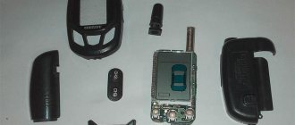
Elements that are included in the Sheriff 750 model:
- Main communicator. It has a feedback function and is equipped with a TFT display. Using this device, the consumer can find out about the status of the anti-theft installation and configure all alarm functions.
- A set of wires for installation and connection of all components of the anti-theft system.
- Additional pager. It does not have two-way communication options, since the device is not equipped with a display.
- Siren with speaker and connection connector. Installation of the device is optional.
- Main electronic module. It is supplied to the market in a black plastic case and equipped with connectors for connecting the main components. Used to process, receive and transmit pulse data.
- Limit switch for mounting on the tailgate or hood.
- Transceiver module. The antenna adapter is equipped with a diode indicator, thanks to which the consumer can find out the alarm status while being at a distance from the machine.
- Valet service button. Used to adjust basic parameters in the absence of a communicator. Can be used for emergency activation and deactivation of the protection mode.
- Dual zone touch sensitivity controller.
- Technical guide for setup and application. Using the Sheriff ZX 750 alarm instructions, the consumer will be able to connect and program all functions of the alarm.
The Sheriff 750 car alarm package includes one limit switch; other devices for installation on the door will have to be purchased separately.
Contents Main functions of the Sheriff ZX system ...
Page 2
- Image
- Text
2
Table of contents
Basic functions of the Sheriff ZX 750 system. . . . . . . . . . . . . . . . . . . . . . . . . . . . . . . . . . . . . . . . . . . . . . . . . . .4
Controlling the operation of the Sheriff ZX 750 system
. . . . . . . . . . . . . . . . . . . . . . . . . . . . . . . . . . . . . . . . . . . . . . .6
Functions of transmitter key fob buttons. . . . . . . . . . . . . . . . . . . . . . . . . . . . . . . . . . . . . . . . . . . . . . . . . . . . . .6 Combinations of LCD indicators. . . . . . . . . . . . . . . . . . . . . . . . . . . . . . . . . . . . . . . . . . . . . . . . . . . . . . . . . . . . . . .7 Programming codes for new transmitters and anti-robbery transponders. . . . . . . . . . . . . .9 Commands for controlling the Sheriff ZX 750 system from the transmitter key fob. . . . . . . . . . . . . . . . . . . . . . . . . .11 Remote (two-way communication key fob) activation/deactivation of system functions. . . . . . .14 Confirmation signals of the two-way communication key fob of the Sheriff ZX 750 system. . . . . . . . . . . . . . . . .17 Operating modes of the security system LED indicator. . . . . . . . . . . . . . . . . . . . . . . . . . . . . . . . .20 Siren signals. . . . . . . . . . . . . . . . . . . . . . . . . . . . . . . . . . . . . . . . . . . . . . . . . . . . . . . . . . . . . . . . . . . . . . . . . . .20 Operating modes of vehicle side lights. . . . . . . . . . . . . . . . . . . . . . . . . . . . . . . . . . . . . . . . . . . . . . .20 Low battery indicator/battery replacement. . . . . . . . . . . . . . . . . . . . . . . . . . . . . . . . . . . . . . . . . .21
Additional commands for arming the system
. . . . . . . . . . . . . . . . . . . . . . . . . . . . . . .22
Passive (automatic) arming of the system. . . . . . . . . . . . . . . . . . . . . . . . . . . . . . . . . . .22 Manually arming the system. . . . . . . . . . . . . . . . . . . . . . . . . . . . . . . . . . . . . . . . . . . . . . . . . . . . . . .22 Arming with the engine running (“Any Stop”). . . . . . . . . . . . . . . . . . . . . . . . . . . . . . . . .23
Car protection in security mode
. . . . . . . . . . . . . . . . . . . . . . . . . . . . . . . . . . . . . . . . . . . . . . . . . . . .23
Protecting the car when the security mode is on. . . . . . . . . . . . . . . . . . . . . . . . . . . . . . . . . . . . . . . . .23 Warning signals about an attempt to break into a car. . . . . . . . . . . . . . . . . . . . . . . . . . . .24 Control of coded blocking relay R350 - function F20 (additional option). . . . . . . . . . .24
Disabling the system
. . . . . . . . . . . . . . . . . . . . . . . . . . . . . . . . . . . . . . . . . . . . . . . . . . . . . . . . . . . . . . . . . . . . .25
Valet button. . . . . . . . . . . . . . . . . . . . . . . . . . . . . . . . . . . . . . . . . . . . . . . . . . . . . . . . . . . . . . . . . . . . . . . . . . . . .25 Manual disabling of the security system using the “Valet” switch. . . . . . . . . . . . . . . . . . . . . .25 Disabling the system using a personal code. . . . . . . . . . . . . . . . . . . . . . . . . . . . . . . . . . . . . . . . .25 Service mode “Valet” (temporary shutdown of the system). . . . . . . . . . . . . . . . . . . . . . . . . . . . . . . . . .26
Additional security features
. . . . . . . . . . . . . . . . . . . . . . . . . . . . . . . . . . . . . . . . . . . . . . . . . . . . . . .26
Additional (emergency) call using the antenna module button. . . . . . . . . . . . . . . . . . . . . . . . . . . . . .26 Automatic safe locking of doors when the vehicle starts moving (function F10.2). . .26 Automatic safe locking of doors when pressing the “C top” pedal of the car (function F10.3). . . . . . . . . . . . . . . . . . . . . . . . . . . . . . . . . . . . . . . . . . . . . . . . . . . . . . . . . . . . . . . . . . . . . . . . . . . .26 Step-by-step sequential unlocking of the driver's then passenger doors (functions F18.1). . . . . . . . . . . . . . . . . . . . . . . . . . . . . . . . . . . . . . . . . . . . . . . . . . . . . . . . . . . . . . . . . . . . . . . . . . . .27 Automatic re-arming of the system (function F6). . . . . . . . . . . . . . . . . . . . . . . . . . . . .27 Disarming the system in two stages - AV function (function F14). . . . . . . . . . . . . . . . . . . . . . . . . . .27 Passive engine blocking (immobilizer function F15) . . . . . . . . . . . . . . . . . . . . . . . . . . . . . .27 “Anti Hi Jack” mode (protection against car theft and seizure). . . . . . . . . . . . . . . . . . . . . . . . . . . . . . . .28 Disabling the “Anti Hi Jack” mode. . . . . . . . . . . . . . . . . . . . . . . . . . . . . . . . . . . . . . . . . . . . . . . . . . . . . . . . .28
Malfunctions and their elimination
Problems with automatic start on the Sheriff ZX complex arise due to incorrect execution of the algorithm for setting the neutral position. The instructions for use require setting the lever to neutral and then applying the parking brake. On the remote control, you need to press the button with the text CH2 twice, then the driver removes the key from the lock and gets out of the car. After activating the security mode, the power unit automatically stops. If the configuration algorithm is violated, further autorun procedure is blocked.
Control failures occur due to a decrease in the battery charge level or due to exposure to airborne interference created by power lines or cellular stations. To disable the security mode, briefly press the programming button, which is performed after unlocking the door and turning on the ignition with the standard key.
If the driver has programmed the shutdown algorithm by entering a PIN code, then after unlocking the door, a cycle of turning on, turning off and turning on the ignition again occurs. The user then enters the first case of the password by pressing the programming key. After re-enabling the ignition circuits, the second register is entered using a similar algorithm. 10 seconds are allotted for entering each digit; if the driver does not meet the required limits, the procedure begins again. After entering the password, the ignition is turned on again, which turns off the alarm.
- Alarm Sheriff APS 2500 instructions
- Sheriff ZX 1070
- APS95LCD B4
- How to disassemble Sherkhan Magikar 5 keychain
Additional service functions for security system management…
Page 3
- Image
- Text
3
Additional service functions for security system management
. . . . . . . . . . . . . . . . . . .29
Remote control of the siren (on/off, night mode of the system). . . .29 Automatic door unlocking when the ignition is turned off (function F11). . . . . . . . . . . . . . . . .29 Remote control of additional devices (CH 2) . . . . . . . . . . . . . . . . . . . . . . . . . . .29 Turning on/off external devices (starting the engine) (function F19.3) . . . . . . . . . . . . . . .thirty
Security system programming
. . . . . . . . . . . . . . . . . . . . . . . . . . . . . . . . . . . . . . . . . . . . . . . . . . .31
Programming system functions. . . . . . . . . . . . . . . . . . . . . . . . . . . . . . . . . . . . . . . . . . . . . . . . . . . . . . . .31 Changing the personal system deactivation code. . . . . . . . . . . . . . . . . . . . . . . . . . . . . . . . . . . . . . . . .32 Table of programmable functions of the Sheriff ZX 750 system. . . . . . . . . . . . . . . . . . . . . . . . . . . . . . . . . .33 Brief description of system functions. . . . . . . . . . . . . . . . . . . . . . . . . . . . . . . . . . . . . . . . . . . . . . . . . . . . . . . . .35
System installation
. . . . . . . . . . . . . . . . . . . . . . . . . . . . . . . . . . . . . . . . . . . . . . . . . . . . . . . . . . . . . . . . . . . . . . .36
Appendix 1. Remote digital locking relay R350, R350NC. . . . . . . . . . . . . . . . . . . . . . . . . . .52
How to find out the alarm model
Having learned the model of the security system, the user will be able to purchase a suitable spare part or replace the communicator. You can identify the alarm using the key fob by opening this device. It is necessary to pry the latches and remove the top cover. The alarm model is recognized by markings on the board. The detected combination of characters is entered into the search bar of the browser and the types of security systems are determined. To find out the alarm model, you need to find the markings in the area of the antenna unit.
Additional functions
Page 5
- Image
- Text
Additional functions
•
“Save” mode—controls the power saving of the two-way communication key fob.
•
Remote control of the “Turbo timer” function (on/off).
•
Temporary blocking of LCD key fob buttons.
•
Remote activation/deactivation of the “Valet” service mode.
•
Search for a car in a parking lot.
•
Remote control of the siren channel in security mode (disable/enable - night mode).
•
Temporarily disabling the shock sensor when arming.
•
Silent communication control mode (manual mode), checking, updating the LCD screen status.
5
Page 38
To install the Valet switch, select a location where the vehicle driver can easily use it. It is recommended to use certain camouflage methods, which will increase the level of system security and make it more difficult for hijackers. The Valet push-button switch can be mounted on the lower driver's side of the vehicle's dashboard.
To install the impact sensor, select a flat, hard surface on the partition separating the engine compartment and the vehicle interior, on the passenger side. Attach the shock sensor to the selected location using two self-tapping screws. The sensor can also be mounted on the pillars to which the car’s dashboard is attached using cable ties. Regardless of which method of mounting the shock sensor is used, it is necessary to ensure free access to the potentiometer for adjusting the sensitivity of the sensor, which may be required for subsequent system setup.
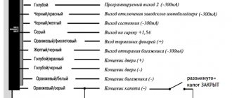
Connecting system wires
When connecting additional relays to the security system outputs, make sure that there is a damping diode on the relay control contacts. Connect the security system output to the additional relay only from the anode side of the snubber diode. Make all connections to the security system wires only with the security system power circuit fuses removed. If there is no damping diode in the additional relay, the polarity of its connection is arbitrary.
Controlling the operation of the sheriff zx 750 system
Page 6
- Image
- Text
Controlling the operation of the Sheriff ZX 750 system
Functions of transmitter key fob buttons
Functions of transmitter key fob buttons
Button for arming the system (ARM) Button for disarming the system (DISARM) Button for controlling the programmable channel CH2, controlling system modes when arming/disarming the system Button “ ” for remote selection of functions and changing system parameters
6
Rice. 1
Attention
In order to increase the battery life of the two-way communication key fob, the presence of communication between it and the central unit of the system is monitored manually. To check the presence of communication with the key fob pager and the system, issue a command by pressing any button except F. If the connection is present, the system will “return” confirmation of the command execution with a corresponding sound signal. Otherwise, after 3 seconds the LCD indicator
antenna will disappear from the screen and the buzzer will
will give one long and one short signal.
Indicator for turning on the power saving mode of the pager key fob...
Page 7
- Image
- Text
7
Indicator for turning on the power saving mode of the pager key fob. The mode is turned on/off in the “Disarmed” mode by simultaneously pressing buttons 1+F(5) until the “Save” indicator appears or disappears. In the “Disarmed” mode, the pager key fob turns off its receiver after 30 seconds, as evidenced by the disappearance of the antenna indicator.
Valet mode activation indicator
(service mode).
Always present on the display while the system is in “Valet” mode.
System sensor status indicator.
The shock sensor is turned off. Triggering in the main zone of the shock sensor is disabled; arming by bypassing a faulty shock sensor. Flashes when the sensor is triggered by a strong impact.
Indicator for turning on the vibrate ringer mode.
“AUTO” indicator—activation of passive arming.
Indicator for turning on door locking during passive or manual arming.
Indicator of the siren sound signal when the “Security” mode is activated.
Indicator of siren deactivation in “Security” mode.
Indicator of anti-burglary function operation. Flashes when the Anti Hi Jack anti-theft feature is activated.
Engine running mode indicator. Flashes in active mode.
Indicator for receiving a call signal from inside the car. Flashes when receiving a call from the pager.
Indicator of operation of temporary timers.
Flashes when the time is counting down in the operating turbo timer mode.
Battery charge indicator (battery is fully charged).
The indicator blinks - low battery charge (less than 30%).
Indicators of activity of additional channels. Shows the status of the CH2 channel line.
Ignition on indicator. Shows the status of the vehicle's ignition line.
LCD display indicator combinations
Communication indicator (antenna).
Disappears if there is no connection with the central unit or if a request is made to execute a non-existent command.
Indicator of the enabled “Turbo timer” mode. Indicates that the mode is activated in the system.
Rice. 2
User manual
The operating instructions supplied with the ZX-750 security complex contain a description of the main functions, as well as a statement of the principles for controlling the operation of the alarm system. Additional sections are devoted to issues of protecting the car when the engine is running and auxiliary algorithms for protecting the car. The documentation contains diagrams for connecting the complex, there is a description of the installation algorithm indicating the requirements for the selection of installation points.
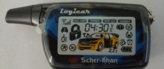
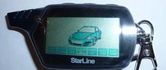
Designation of buttons and icons on the key fob
The equipment is equipped with a communicator, which contains 4 buttons (on the end edge). The keys allow you to turn protection on or off, control an additional channel, or select functions when changing the parameters of the complex. To increase the service life of the battery, a manual algorithm was used to check the connection between the transmitter and the receiver in the car. To check the channel, briefly press any key (except for the button with the letter F). If the poll is correct, a signal is generated by the built-in speaker.
The remote control display contains icons that allow you to control the operation of the security system components. Additional icons are designed to display the operation of the motor during automatic start. There is also an icon that turns on when a call comes from inside the car, and there is a battery charge level indicator.
Setting up the key fob
To record the control panel code into memory, you will need to perform the following steps:
- When security is turned off and the ignition is active, the programming start button is pressed 3 times. After the siren sounds, you need to press the button again.
- After a long beep, you need to press down the button with the locked lock icon on the key fob. After recording the code, a short signal is given by the siren, accompanied by the start of the control indicator (in flashing mode).
- Repeat the procedure with the remaining devices, the interval between recording codes does not exceed 5 seconds. To complete the process, you must turn off the ignition or wait 8 seconds (without pressing the buttons on the control panels). The correct completion of programming is confirmed by a double beep (long and short). The control diode on the transceiver turns off.
Setting up autorun
To ensure autostart, you must first program the function responsible for sending a negative pulse in the additional channel.
To activate the launch, you need to press the buttons with the locked lock signs and the text CH2 at the same time.
After turning on the external lighting equipment, the power unit starts and warms up (every 4 hours). The user does not have the ability to regulate the operating time of the motor and select the sensors based on the signals from which the engine starts.
Door status indicator: ...
Page 8
- Image
- Text
8
Door status indicator:
— on (doors locked)
with the ignition on or in “Valet” mode (service mode).
- off (doors unlocked)
us) with the ignition on or in the “Valet” mode (service mode).
System command execution indicator. The headlights are flashing.
Hood switch activation indicator. Flashes when the hood switch is triggered in the “Armed” mode or when arming with the hood open.
Door limit switch operation indicator. The door icon flashes when the system is triggered by the door limit switches or when arming bypassing faulty (unready) door limit switches.
Trunk limit switch activation indicator. Flashes when the trunk limit switch is activated in the “Security” mode or when arming with the trunk open.
Programming codes for new transmitters, Programming transmitters
Page 9
- Image
- Text
9
Programming codes for new transmitters
Important
Please note that when programming a new transmitter into the system memory, all previously programmed transmitter codes are erased, therefore, when programming additional transmitters, existing transmitters must be programmed again. The system maintains up to four key fob codes in memory, regardless of whether the codes are from four different key fobs or the same code is written into the system 4 times.
Transmitter programming
Recording codes for new transmitters (F13 - “Valet” state).
Important
Remember that each operation must be performed within 5 seconds after the previous operation. If the 5 second interval is exceeded, the system will automatically exit the programming mode, which will be confirmed by one short and one long beep from the siren. If the ignition was turned off during programming, the system will immediately exit the programming mode, confirming this with one short and one long siren signal.
•
Disarm the system, get into the car and turn on the ignition.
•
Press the Valet button switch 3 times. You will hear one short siren signal. Click the Valet button again. You will hear a long siren tone indicating that the system is ready to program new transmitters.
•
Press and hold button 1 (see Fig. 1) of the first transmitter until you hear a long siren signal, confirming that programming of the first transmitter is completed (the transmitter channels will be programmed automatically). At the same time, the LED will begin to flash rapidly.
•
Press and hold button 1 (see Fig. 1) of the second transmitter until you hear a long siren signal confirming that programming of the second transmitter is complete. The LED will begin to flash slowly.
•
Repeat step 3 for the remaining transmitters.
•
To exit transmitter programming mode:
a) turn off the ignition or b) wait 8 seconds without performing any actions.
You will hear one short and one long siren signal to confirm exit
transmitter programming, and the system LED will go out.
Recording codes for new transmitters (F13 - “Secret code” state)
Disarm the system using a key fob or by entering a secret code with the “Valet” button, i.e. •
Turn on, turn off and then turn on the ignition;
•
Using the “Valet” switch, enter the first digit of the code (the number of presses of the “Valet” button corresponds to one digit of the code);
•
Turn off and then turn on the ignition;
•
Using the “Valet” switch, enter the second digit of the code (the number of presses of the “Valet” button corresponds to the second digit of the code);
•
Turn off and then turn on the ignition. The system should confirm with an audible signal that the correct code has been entered;
How to install?
An example of installing an anti-theft system on a car:
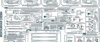
- Analysis of electrical circuit traces is carried out. The car owner needs to think through all the ways of laying cables in the car interior, luggage compartment and under the hood. The consumer must start from the installation location of the electronic module, sensitivity controller, siren and transceiver. Each conductor is characterized by its own color marking. The cable is laid to a specific device marked on the connection diagram. Conductors are laid along existing power line routes. When laying, it is important to think through the nuance in advance so that the driver or passenger cannot accidentally damage the wiring.
- The secret key is installed in the area of the driver's left foot, under the instrument panel. To install the button hidden, you can install it in the air duct or, for example, behind the center console. But keep in mind that as long as the car owner has access to the key during an emergency operation, the siren is functioning. It is more difficult to ensure a high-quality connection of cables with buttons for opening door locks. The power lines will have to be extended and laid under the plastic thresholds in the car interior. When connecting electrical circuits, take into account the sections included in the package.
- At the next stage, the lining in the car interior is removed, under which the wiring will be laid. You can dismantle the thresholds first on the right side and then on the left.
- Then all electronic signaling modules are installed. It is not allowed to install motion and shock controllers on clamps, as this will lead to false alarms.
- After installing the modules, power lines are laid to the installation sites of the devices.
- The terminals from the battery are disconnected as electrical cable connections will be made. We recommend connecting conductors by twisting and then soldering. After this, the soldering area is insulated with a special heat-shrinkable tube or insulating tape. Fixing the conductors to existing wiring harnesses is done using plastic clamps. The connection of power lines to grounding is done through standard ground points. Typically, such wires are made in black or brown, they are clamped using 10mm bolts.
- Installation of conductors to the ignition switch is carried out after installing and connecting the main components. This is due to the need to break the electrical circuit of the starter device. If you plan to use an engine blocker bypass, it should be connected to the immo pumping loop. The latter is located on the end of the lock. Installation of safety devices is carried out on all electrical circuits that need to be protected. The fuse rating is selected in accordance with the amount of current passing through the conductors.
- At the last stage of the work performed, the quality of the connected connections is diagnosed. The consumer must test all connections using a multimeter or voltmeter. If the car owner has no experience in performing such a task, then it is better to entrust the procedure to specialists.
Press the push button switch...
Page 10
- Image
- Text
•
Press the Valet button switch 3 times. You will hear one short siren signal. Click the Valet button again. You will hear a long siren signal confirming that the system is ready to program new transmitters;
•
Press button 1 (see Fig. 1) of the first transmitter key fob. The system will confirm the recording of the new key fob code into memory with a sound signal;
•
Press button 1 (see Fig. 1) of the second transmitter key fob. The system will confirm the recording of the new key fob code into memory with a sound signal;
•
Repeat step 3 for the remaining transmitters;
•
To exit transmitter programming mode:
a) turn off the ignition or b) wait 8 seconds without performing any actions.
You will hear one short and one long beep from the siren to confirm that you have exited the mode.
transmitters and the system LED will go out.
10
Comments
Select → I found instructions for my car alarm here! #manualza
- Click →
The owner of Ikea sold his soul to the devil, but he could not assemble it according to the instructions.
Manualza!manualza.ru
Still not with us?
Advantages and disadvantages
Advantages of the 750 models:
- Efficiency. At a relatively low price, Sheriff 750 alarm systems are characterized by operating efficiency under any conditions.
- Long service life. According to reviews, the alarm system of this model optimally performs its functions even several years after installation.
- Wide functionality. The options that the signaling has allow you to comfortably control not only the system itself, but also some components of the car. At a low cost, optionality will be a nice addition.
- Availability of feedback.
This model has more disadvantages than advantages:
- Small range of the communicator. The actual operating range of the remote control differs from that declared by the manufacturer. If there is interference on the ground, the operating radius can be reduced to several hundred meters.
- Quiet speaker on the pager. Users complain that the notifications that come to the device are played too quietly. It is not always possible to hear the signals that the alarm sends to the pager.
- The siren goes off for no reason. The device can trigger an alarm mode in the absence of physical impact on the car body. In fact, this may be due to incorrect settings of the sensitivity sensor. Proper adjustment can solve the problem.
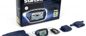
- Fragile keychain. The device is sold in a weak case that is susceptible to breakage as a result of falls. Many consumers are faced with the need to repair their communicator.
- The appearance of signal malfunctions after a certain time. Although the service life of the anti-theft installation is quite long, problems appear over time. Alarms may go off for no reason, door locks may not lock, etc.
A brief overview of the capabilities and disadvantages of the signaling was given by user Yaroslav540.