The ignition module is a mechanism whose malfunctions are very difficult to identify. Usually, problems begin to be solved when it becomes obvious that something is wrong with the car. If your VAZ 2107 does not start the first time, you cannot set the ignition, and uneven engine operation begins to confuse you - it’s time to carry out a proper check. Let us recall that the engine ignition module of the “injector” type is the same system that, with the help of coils, supplies electrical energy in order to form a spark and start the car.
Connection diagram for VAZ 2107 switch
The contactless ignition system of the VAZ 2107 includes:
- Candles.
- Ignition distributor (sensor).
- Anti-interference screen.
- Non-contact slider position sensor.
- Switch that controls spark generation.
- Ignition coil.
- Assembly block.
- Ignition switch relay.
- Ignition switch on the steering column.
Wire “A” goes to the positive terminal of the car generator output. The connection diagram for the VAZ 2107 switch is shown in the figure:
Signs of a malfunction of the VAZ 2107 switch
The main symptom of a switch failure is the absence of a spark at the spark plugs. Alternatively, the spark may not be powerful enough or disappear periodically. In this case, the engine starts poorly, runs intermittently, stalls at idle, loses power, or its speed constantly fluctuates. It should be remembered that all these signs can also appear due to malfunctions of other parts of the ignition system: the Hall sensor. wires and spark plugs, ignition coil, distributor. The spark also disappears when the timing belt breaks and there is no contact in the power supply circuit of the ignition system. To accurately determine the cause, it is necessary to separately check the functionality of the switch.
What to do before setting the ignition
First you need to make sure that:
- all spark plugs work, the gaps are adjustable, there is no soot, the top is a spark plug with soot, the bottom is normal.
- clean the coil, distributor cap and distributor contacts from dirt and dust;
- the contact and quality of the wire from the coil are good, the ignition coil is working;
- reinforced wires have good insulation, contact with candles;
- check the distributor contacts to see if they are burnt out. If they are burnt out, they must be replaced;
- Ignition adjustment should be made with the engine fully warmed up.
Types of ignition systems VAZ 2107
The evolution of the VAZ 2107 has transformed the ignition system of this car from an unreliable mechanical design into a modern computer-controlled electronic system. Changes occurred in three main stages.
Contact ignition of carburetor engines
The first modifications of the VAZ 2107 were equipped with a contact-type ignition system. This system worked as follows. The voltage from the battery was supplied through the ignition switch to a transformer (coil), where it increased several thousand times, and then to a distributor, which distributed it among the spark plugs. Since voltage was pulsed to the spark plugs, a mechanical breaker located in the distributor housing was used to close and open the circuit. The breaker was subjected to constant mechanical and electrical stress, and it often had to be adjusted by setting the gaps between the contacts. The contact group of the device had a short resource, so it had to be changed every 20–30 thousand kilometers. However, despite the unreliability of the design, cars with this type of ignition can still be found today.
The contact ignition system requires adjustment of the gap between the breaker contacts
Contactless ignition of carburetor engines
Since the beginning of the 90s, a contactless ignition system was installed on carburetor VAZ 2107, where the breaker was replaced with a Hall sensor and an electronic switch. The sensor is located inside the ignition distributor housing. It reacts to the rotation of the crankshaft and sends a corresponding signal to the switching unit. The latter, based on the data received, supplies (interrupts the supply) voltage from the battery to the coil. Then the voltage returns to the distributor, is distributed and goes to the spark plugs.
In the contactless ignition system, the mechanical breaker is replaced by an electronic switch
Contactless ignition of injection engines
The latest VAZ 2107 models are equipped with electronically controlled injection engines. The ignition system in this case does not provide any mechanical devices at all, not even a distributor. In addition, there is no coil or commutator as such. The functions of all these components are performed by one device - the ignition module.
The operation of the module, as well as the operation of the entire engine, is controlled by the controller. The principle of operation of such an ignition system is as follows: the controller supplies voltage to the module. The latter converts the voltage and distributes it among the cylinders.
Types of systems
For decades, while the VAZ 2107 model was produced (from 1982 to 2012), it was equipped with three types of ignition systems:
- controlled by an electronic unit (ECU).
- contactless;
- mechanical with contacts – switches;
The contact ignition circuit was installed on early VAZ 2107 models
Note. The first 2 varieties were installed on the “seven” with a carburetor, the latter was introduced along with an injector.
In the mechanical version, the open contacts of the distributor shaft cam interrupt the low voltage circuit, initiating the formation of a powerful pulse in the secondary winding of the coil. This discharge is directed to the spark plug electrodes, which ignites the fuel in the cylinder where the piston has risen to top dead center (TDC) and the compression stroke has completed.
Scheme of non-contact ignition of the seven with a carburetor
The contactless circuit works on the same principle, only the Hall sensor gives a signal to open the circuit, and the switch implements it. Therefore, the ignition setting on the “seven” carburetor is almost the same. Another thing is injection cars, where a new system has been introduced, in which there are not only contacts, but also a distributor and any moving parts. Here, the moment of spark formation is determined by the ECU controller, which is controlled by signals from various sensors.
VAZ 2107 Ignition system with injector
Distributor
The ignition distributor (distributor) is designed to transmit high-voltage current pulses that come from the coil to the spark plugs. The distributor consists of:
- aluminum body;
- shaft;
- Hall sensor;
- vacuum and centrifugal ignition timing regulators;
- runner;
- covers with four fixed contacts.
In “sevens” with contactless ignition, distributors of type 38.3706 are used.
A Hall sensor is installed on the distributor 38.3706
Table: technical characteristics of distributor type 38.3706
| Characteristics | Indicators |
| Supply voltage, V | 12 |
| Permissible speed, rpm | 3500 |
| Switching on the centrifugal regulator at, rpm | 400 |
| Maximum angle of the centrifugal regulator, o | 15,5 |
| Turn on the vacuum regulator at, mm. Hg Art. | 85 |
| Maximum angle of the vacuum regulator, o | 6 |
| Operating temperature range, oС | -40 — +100 |
| Weight, kg | 1,05 |
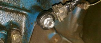
Where is the distributor located in the VAZ 2107
The ignition distributor is mounted on the left side of the engine cylinder block. Its shaft is driven by the auxiliary drive gear. The number of revolutions of the distributor shaft directly depends on the speed of rotation of the crankshaft.
The distributor is located on the left side of the cylinder block
Malfunctions of the VAZ 2107 distributor and their symptoms
The most common breakdowns of the “seven” distributor include:
- burning of the fixed contacts of the cover;
- mechanical damage or electrical breakdown of the cover;
- burning of the runner.
As for the symptoms, for the listed problems they will be similar:
- unstable engine operation;
- reduction in power characteristics of the power plant;
- increased fuel consumption.
To diagnose major distributor failures, it does not need to be removed from the engine. It is enough to disconnect the high-voltage wires from the cover and unfasten the two latches that secure it to the body. By removing the cover and inspecting the contacts with the slider, you can visually assess their condition and draw a conclusion about how suitable they are for further work. If the contacts cannot be cleaned, the device cover must be replaced. Such a part costs about 200 rubles. The runner will cost half as much.
The distributor cover is attached to its body using two latches
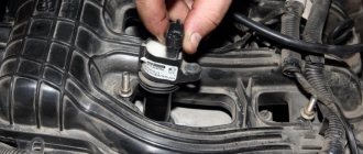
Checking the secondary windings of the module
First, disconnect the wire ends from it. If you have already done this, then place it exactly in front of you. Then install the device to the upper and lower right outputs and carefully monitor the indicators that the device will display in a second.
After this, we perform exactly the same actions with the upper and lower left exits. Naturally, the ohmmeter readings should change and ideally be at least 7 ohms.
If at least one coil does not meet the standards, then in order to avoid unforeseen situations with your VAZ 2107, we recommend replacing the entire module.
Instructions for setting the ignition
If you strictly followed the instructions, connected all the wires according to the diagram and did not misalign the marks, then the motor will start without problems. To adjust the ignition, you need to ensure stable engine operation, so first warm it up for a few minutes, without letting it stall by pressing the gas pedal.
Adjustments can be made on a warm engine using two methods:
- without the use of special devices - “by ear”;
- fine adjustment using a strobe light.
A strobe is a device with a light bulb that flashes simultaneously with the transmission of a pulse by the Hall sensor. When the switched on strobe is brought to the crankshaft flywheel with the engine running, the position of the notch becomes visible. Hence the possibility of precise adjustment.
This is what a strobe looks like for fine-tuning the ignition
To set up, connect the strobe power supply to the battery, and the thick wire to the high-voltage wire of the spark plug of the 1st cylinder. Loosen the distributor fastening nut and bring the flashing lamp to the pulley. Slowly turn the distributor body until the notch on the pulley aligns with the short notch, then tighten the nut.
Tuning in the traditional way “by ear” is done like this:
- Start the engine and loosen the nut holding the ignition distributor.
- Rotate the distributor smoothly and slowly within 15°. Find the position at which the motor operates most stably.
- Tighten the fastening nut.
When adjusting, turn the distributor by the membrane body
It is quite natural that after installing a contactless ignition system, the engine idle speed will increase to 1100-1200 rpm due to the increased spark power. Set the rate to 850-900 rpm by tightening the idle screw on the carburetor and using the tachometer as a guide. On VAZ 2105-2107 carburetors of the “Ozone” type, this screw is located in the lower section of the unit on the right side and is large in size. The VAZ 2108 carburetors of the Solex type (these were also installed on the “seven”) have a long plastic handle protruding from the right (in the direction of travel). The second screw, which regulates the composition of the air-fuel mixture, cannot be turned.
The arrow shows the idle speed adjustment screw.
Carburetor
There are a large number of strobe lights on the market, but in general their operating principle is equally suitable for ignition installations. The price only affects the service life of this device. The strobe light operates while the engine is idling. The ignition is adjusted by aligning the marks on the crankshaft pulley with the scale on the timing cover. The matching of signs is assessed using a stroboscopic light beam.
When using a VAZ 2107 with 92 or 95 gasoline, the average mark of the scale should coincide with the pulley mark. In case of deviation, the ignition angle must be adjusted by turning the distributor housing. When turning the distributor clockwise, the advance angle increases, and when moving in the opposite direction, it decreases.
How to carry out repairs
If a breakdown is detected, the damaged coil must be removed. To complete the work you will need a set of wrenches.
Removing the module
To remove a faulty unit, you will need:
- Disconnect the battery from the on-board network and remove the air filter housing.
- Disconnect the high-voltage cables and wiring harness.
- Remove the 3 nuts that hold the assembly to the mounting pad.
Replacement features
You can install the coil without using a special tool. The ignition system of injection engines does not require any adjustments. The throttle position is adjusted in idle and maximum gas modes. In case of malfunctions, it is necessary to check and align the crankshaft position sensor to the marks on the drive pulley of external units.
https://youtube.com/watch?v=h-b_85f0QMI
Carrying out repairs
The module is repaired if it is not possible to buy a new product. The lower part of the case is opened, and then the damaged tracks are restored. It is impossible to repair the coils in artisanal conditions; the parts are not supplied to the spare parts market. To perform installation work, soldering equipment and skills in working with equipment are required. Rebuilding ignition coils is not recommended.
How to remove the coil
If your fears are confirmed, and the coil really needs to be replaced, then installing a new one will not be difficult.
To do this, first remove the air filter housing, then the negative wire terminal from the battery and disconnect the high-voltage wires from the module. Having removed the wires located there from the module cover, unscrew the three nuts that secure it and disconnect it from the bracket.
That's all. Even a novice VAZ 2107 driver can perform such simple manipulations. If you already have a new part, then immediately after removing the coil you can install it. To do this, you need to perform all the steps we previously described in reverse order.
If it happens that you suddenly forgot how the high-voltage wires were originally located, then thanks to one little hint from a caring manufacturer, you won’t have to fiddle around for long. The secret is that on the module itself the numbers of the cylinders to which the wires must be connected are indicated.
The process of replacing spark plugs
Required tools and materials:
- Spark plug head 16 mm;
- Spark plug head 21 mm;
- Candle tube;
- Clean rags.
Step-by-step instructions for replacing spark plugs in a Chevrolet Niva:
- Open the hood of the vehicle.
- Remove high voltage wiring. If necessary, take a photo or note the sequence of wire installation.
- Using a feeler gauge, check the gap between the spark plug electrodes.
- Check the gap of the new spark plugs.
- Screw the new parts back in with a torque of 31-39 Nm (the order in which the spark plugs are installed does not matter).
- Install the ignition wires in the same sequence as removal.
The procedure for replacing spark plugs on a Chevrolet Niva has been completed.
About the drive mechanism
To transmit torque to the distributor shaft on the “six”, a helical gear is used, rotated by a timing chain (in common parlance – “hog”). Since the element is located horizontally and the distributor roller is vertical, there is an intermediary between them - the so-called fungus with oblique teeth and internal slots. This gear simultaneously turns 2 shafts - the oil pump and the distributor.
The distributor drive consists of two transmission gears with oblique teeth
Both transmission links - the “hog” and the “fungus” - are designed for a long service life and are replaced during engine overhauls. The first part is removed after disassembling the timing chain drive, the second is pulled out through the upper hole in the cylinder block.
The VAZ 2106 distributor, equipped with a contact breaker, is a rather complex unit consisting of many small parts. Hence the unreliability of operation and constant failures of the spark generation system. The non-contact version of the distributor creates problems much less frequently, but in terms of performance characteristics it still falls short of modern ignition modules, which have no moving parts.
Ignition module
The ignition module is a device designed to convert DC voltage from the on-board network into electronic high-voltage pulses with their subsequent distribution among the cylinders in a certain order.
In the injection VAZ 2107, the ignition module replaced the coil and switch
Design and operating principle
The design of the device includes two two-terminal ignition coils (transformers) and two high-voltage switches. The voltage supply to the primary windings of the transformer is controlled by the controller based on the information received from the sensors.
The operation of the ignition module is controlled by the controller
In the ignition system of an injection engine, voltage distribution is carried out according to the idle spark principle, which provides for the pairwise division of cylinders (1–4 and 2–3). A spark is formed simultaneously in two cylinders - in the cylinder in which the compression stroke is coming to an end (working spark), and in the cylinder where the exhaust stroke begins (idle spark). In the first cylinder, the fuel-air mixture ignites, but in the fourth, where the gases burn out, nothing happens. After turning the crankshaft half a turn (180), the second pair of cylinders enters the process. Since the controller receives information about the exact position of the crankshaft from a special sensor, problems with sparking and its order do not arise.
Location of the ignition module VAZ 2107
The ignition module is located on the front side of the cylinder block above the oil filter. It is secured to a specially designed metal bracket using four screws. It can be identified by the high-voltage wires coming out of the housing.
The ignition module is located on the front of the cylinder block above the oil filter
Factory designations and characteristics
VAZ 2107 ignition modules have catalog number 2111–3705010. As an alternative, consider products numbered 2112–3705010, 55.3705, 042.3705, 46.01. 3705, 21.12370–5010
They all have approximately the same characteristics, but when purchasing a module you should pay attention to the engine size for which it is intended
Table: technical characteristics of the ignition module 2111–3705010
| Name | Index |
| Length, mm | 110 |
| Width, mm | 117 |
| Height, mm | 70 |
| Weight, g | 1320 |
| Rated voltage, V | 12 |
| Primary winding current, A | 6,4 |
| Secondary winding voltage, V | 28000 |
| Duration of spark discharge, ms (not less) | 1,5 |
| Spark discharge energy, MJ (not less) | 50 |
| Operating temperature range, C | from -40 to + 130 |
| Approximate price, rub. (depending on manufacturer) | 600–1000 |
High voltage wires
High voltage wires (HVW) transmit impulses from the coil to the spark plugs. Unlike other wires, they must not only withstand high voltage, but also protect other parts of the car from it. Each wire consists of a conductor with a metal tip, rubber caps on both sides and insulation. The serviceability and reliability of the insulation is of great importance, since it:
Malfunctions of high-voltage wires
The following main malfunctions are characteristic of GDP:
If the VV is damaged, the electrical contact is lost and a discharge occurs, leading to voltage loss. In this case, the spark plug receives not the rated voltage, but an electromagnetic pulse. Faulty wires lead to improper functioning of some sensors and interruptions in the operation of the power unit. As a result, one of the cylinders stops performing useful work and runs idle. The power unit loses power and begins to detonate. In this case, they say that the engine is “troubling.”
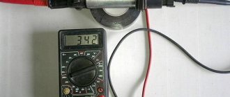
Diagnostics of high-voltage wires
If you suspect a malfunction of the engine (the engine is “troubling”), they must first be carefully inspected - damage to the insulation, chips, or contact with hot engine elements is possible. Particular attention should be paid to the wire contacts - there should be no traces of oxidation or soot on them. If no visible damage is found, proceed to detect a possible break and measure the resistance of the GDP using a multimeter. The wire resistance should be 3–10 kOhm. If it is zero, the wire is broken. It should also be taken into account that the resistance should not deviate from the norm by more than 2–3 kOhm. Otherwise, the wire should be replaced.
Selection of high voltage wires
When purchasing new wires, you should pay attention to the car manufacturer's recommendations. The VAZ 2107 is usually equipped with VPPV-40 (blue) wires with distributed resistance (2550 +/-200 Ohm/m) or PVVP-8 (red) with distributed resistance (2000 +/-200 Ohm/m). An important indicator of GDP is the permissible voltage. If the actual voltage values exceed the permissible values, breakdown of the cable insulating layer may occur and the wire may fail. The voltage in a non-contact SZ reaches 20 kV, and the breakdown voltage is 50 kV.
The material from which the GDPs are made is also important. Typically the wire has polyethylene insulation in a polyvinyl chloride sheath. Silicone GDPs are considered the most reliable. They do not become rough in the cold, which prevents them from loosening in their nests, and are less prone to breakdowns. Wire manufacturers include Champion, Tesla, Horse, and others.
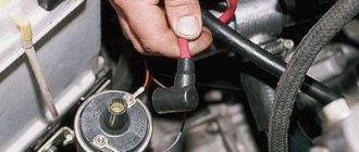
Checking the ignition coil
The coil is checked based on two indicators: the presence of a short circuit and an open circuit. Before diagnostics, the ignition coil must be disconnected. After this, one probe of the device is connected to the central contact of the coil, the second to the body (ground). If the display shows resistance equal to infinity, there is no short circuit.
The primary winding of the coil for a break occurs differently. The probes of the device must be connected to the right and left contacts. The resistance between them should be within 3-3.5 Ohms.
If the resistance of the primary winding does not correspond to the norm or there is a short circuit in the coil to the housing, it must be replaced.
Proper short circuit check
First, check the coil winding for short circuits. To do this, you need to connect a multimeter that determines the resistance. Before checking, it is recommended to lubricate the tip of the high-voltage wire with a special lubricant, which can be purchased at any spare parts store for the VAZ 2107, or with technical petroleum jelly.
We disconnect the module from the tips and connect one terminal of the device to the central contact that the coil has, and the other to ground. If the device display shows “infinity”, this means that there is no short circuit - that is, everything is in order. It is worth noting that if, when ringing the circuit, the display indicators did not change (and, for example, the number one was preserved), then this is infinity.
Now let's check the primary ignition circuit for an open circuit.
To do this, you will need to install a multimeter to the left and right contacts, which are responsible for the ignition function. With this installation, the ohmmeter should change its readings. Otherwise, it will be not just the coil that needs to be replaced, but the entire device. Please note that the normal value is 3-3.5 ohms.
How to check the ignition of a VAZ 2106 with a multimeter
In order to check the coil with a multimeter, we need the multimeter itself and, of course, the ignition coil itself. take a multimeter and set it to 200-ohm, then check the terminals (B - K), the resistance should be at least in the range of 04.0-ohm, the resistance range is from 03.8 to 04.5-ohm, this is the norm; there’s clearly something wrong with the coil; now we need to check the high-voltage part; we set it measurement mode 20-klom 1 any probe on mark B or K another on the high-voltage contact resistance 7.6 klom 7 to 8 klom this is the norm This means your coil is intact, but also do not forget that there may be an internal breakdown of the coil, that is, a breakdown of the insulation between the high-voltage and low-voltage winding and also the interturn one, and you also need to check the case, that is, also at 20 kL, we leave the relative mass for each contact, we check because we came across coils, so we check everything is fine on the case, it breaks through, and if there are no short circuits between the winding and interturn circuits, then it will function.
About their device
Before finding out the importance of the elements of the ignition system in question, it is necessary to understand their structure. Structurally, the high-voltage wire consists of the following parts:
- A conductor through which current flows.
- Insulation - rubber or silicone is used as an insulating material.
- Protective caps on both ends.
- Metal contacts.
Each element performs corresponding tasks, and at the slightest violation of integrity, it will be necessary to replace it. Armored wires cannot be repaired, since they play one of the main roles in the car’s ignition system, and also belong to the category of consumables.
To distributor or MZ
It is a mistaken belief that armored wires on a car are ordinary wires that are designed to transmit current from a source to a receiver. As you know, VAZ 2107 cars were produced in two variations of the fuel supply system - carburetor and injector. Although many parts and mechanisms on the carburetor and injector are the same, this does not apply to the GDP. The carburetor VVP differs from the injection one on the VAZ 2107 in the following parameters:
- The length, on which the amount of resistance also depends. The wires on the injection unit are shorter than on the carburetor.
- Fasteners that connect to the distributor on the carburetor and the ignition module on the injector.
- The amount of GDP. There are four of them on the injector, and five on the carburetor.
- Type of caps.
Knowing the design differences, you must also understand that high voltage flows through the wire. The current comes from the distributor or MG through the wires to the spark plugs. The slightest malfunctions lead to the fact that current is not supplied to the spark plug, and a spark does not occur. If a spark does not occur, the cylinder does not work, which negatively affects the operation of the engine.
Injector
The VAZ 2107 was produced with two types of engines - injection and carburetor. Modifications with a fuel injection unit have a special design and electronic ignition control is not required. The adjustment occurs automatically: the ECU uses sensors to determine the ignition timing and all other details. The participation of car owners in this procedure is limited to aligning the timing chain or belt using marks.
If problems arise with the electronic ignition of a Lada 2107 on an injection engine, it is necessary to flush the injector and replace the failed components.
Adjusting the ignition on the VAZ 2107 injector.
Product delivery options
Note! Below are the shipping methods available specifically for this product. Payment options may vary depending on the delivery method.
Detailed information can be found on the “Delivery and Payment” page.
Parcel by Russian Post
Available payment methods:
- Cash on delivery (payment upon receipt)
- Using cards Sberbank, VTB, Post Bank, Tinkoff
- Yandex money
- QIWI
- ROBOKASSA
Shipping throughout Russia. Delivery time is from 5 to 12 days.
Parcel by Russian Post 1st class
Available payment methods:
- Cash on delivery (payment upon receipt)
- Using cards Sberbank, VTB, Post Bank, Tinkoff
- Yandex money
- QIWI
- ROBOKASSA
Shipping throughout Russia. Delivery time is from 2 to 5 days. More expensive than regular delivery by Russian Post, approximately 50%. Parcel weight up to 2.5 kg
Express Parcel EMS
Available payment methods:
- Cash on delivery (payment upon receipt)
- Using cards Sberbank, VTB, Post Bank, Tinkoff
- Yandex money
- QIWI
- ROBOKASSA
Shipping throughout Russia. Delivery time is from 3 to 7 days. More expensive than regular delivery by Russian Post, approximately 100%.
The principle of operation of the ignition system of the VAZ 2106
Almost all classic models are traditionally equipped with a standard contact-type ignition system (KSZ). An exception is 21065, which uses a non-contact transistor circuit in which an interruption of the primary winding power circuit is realized using a breaker mounted in the distributor. Below we will consider in more detail how the contact ignition system of the VAZ-2106 is designed and works.
VAZ 2106 ignition system diagram
The design of the ignition contact circuit includes the following components:
- lock (switch);
- coil (short circuit);
- breaker (MP);
- distributor (MR);
- regulators, centrifugal and vacuum (CR and VR);
- candles (SZ);
- high-voltage wires (VP).
Let's take a look at the ignition coil and take a closer look at what it is needed for and what it is responsible for.
Switch
The commutator is necessary to create an electrical impulse by interrupting the constant supply of current from the battery to the primary winding of the coil. The BSZ VAZ 2107 uses a switching device of type 3620.3734. The working elements in it are ordinary bipolar transistors, which open the circuit when a signal is received from the Hall sensor.
Switch 3620.3734 is built according to a simple single-wire circuit, in which the device body is connected to the vehicle ground and, accordingly, to the negative terminal of the battery. The advantages of using this unit instead of a traditional breaker include:
- no need for maintenance or adjustment;
- high spark energy, which makes it easier to start the engine in the cold season, as well as the ability to use gasoline with a lower octane number;
- the presence of a stabilization system that protects the Hall sensor from voltage surges.
This switch has one drawback - low production quality. It happens that the device fails after just a few months of use. Its design is non-demountable, therefore, repair is impossible. That is why experienced owners of “Sevens” and other VAZs with a contactless ignition system carry spare switches in their cars. Fortunately, the part is inexpensive - 400–500 rubles.
Signs of a faulty ignition coil
If, after turning the key in the ignition switch, you hear that the starter is turning, but the engine does not start, then, as a rule, this may mean that the ignition coil is not working correctly or has failed. Although there are many reasons why the engine does not start when you try to start it: spark plugs, explosive wires, problems in the fuel system (pump, fuel filter, clogged line), and so on...
But if, after all, the reason is in the ignition coil, then this can be understood by the following symptoms:
- There is no spark at the spark plugs;
- There is no current on the BB wires;
- Visual defects (cracks and chips on the reel body);
- A burning smell under the hood, which leaves traces of melting of the ignition coil (the primary or secondary winding has burned out).
A few words about the BZS (Contactless ignition system) VAZ 2106
The coil operating as part of a contactless circuit differs in the number of turns of the primary and secondary windings. Simply put, it is more powerful than the old version, since it is designed to create pulses of 22-24 thousand volts. The predecessor supplied a maximum of 18 kV to the spark plug electrodes.
The cable with connectors is used for reliable connection of the terminals of the ignition distributor and the switch. The structure of these two elements should be considered separately.
In terms of reliability, the BSZ is significantly superior to the outdated contact ignition of the “six”; problems arise much less frequently and are easier to diagnose.
All elements of the system are connected to each other and to the engine as follows:
- The distributor shaft rotates from the motor drive gear;
- The Hall sensor installed inside the distributor is connected to the switch;
- the coil is connected by a low voltage line to the controller, a high voltage line to the central electrode of the distributor cover;
- high-voltage wires from the spark plugs are connected to the side contacts of the main distributor cap.
The threaded clamp “K” on the coil is connected to the positive contact of the ignition switch relay and terminal “4” of the switch. The second clamp marked “K” is connected to contact “1” of the controller, and the tachometer wire also comes here. Terminals “3”, “5” and “6” of the switch are used to connect a Hall sensor.
One of the effective options is to replace the standard ignition system with a non-contact ignition system (abbreviated as BSZ), where electronics are in charge of sparking
The main components of the distributor and a description of its operation
VAZ classic distributor device
Device
The distributor is assembled in a housing. Inside it, a contact group is mounted on a bearing: moving and fixed contacts or a Hall sensor (for contactless ignition). To correct the advance angle, the vacuum regulator can rotate the contact group at a small angle relative to the housing. The capacitor is attached to the bottom of the case with screws. A drive roller is mounted on bushings in the center of the body. Its bottom has splines with which it engages with the drive gear. In the upper part of the roller there are contact drive cams (for contact ignition) or a steel cup with four slots - a screen (for contactless ignition). At the very top, on a steel platform, two weights and two springs of the centrifugal ignition regulator are installed. A plastic housing with a moving contact and noise suppression resistance of the high voltage distributor (slider) is screwed onto the top with two screws. The entire structure is closed with a lid on two spring latches. The body and cover have a tongue and groove so that they fit together in only one position. The cover contains contact terminals for high voltage wires from the spark plugs and from the ignition coil. The distributor is secured to the engine block using a stud, nut and pressure washer. To adjust the ignition timing, the housing can be rotated relative to the block.
Job
The distributor is connected through the drive to the engine crankshaft and rotates with it. For two full revolutions of the crankshaft, the distributor shaft makes one revolution. This is due to the fact that our engine is four-stroke. When installing the distributor in place, the roller is oriented in strict accordance with the operating order of the engine. This is done so that the contacts open and the spark jumps on the spark plug when the piston of each cylinder, compressing the combustible mixture, does not reach top dead center (TDC) by a few millimeters. This is called ignition advance. When the number of revolutions increases, the distance must be increased, and when it decreases, it must be decreased, which is what the centrifugal regulator does. Its weights, under the influence of centrifugal force, which is greater the higher the engine speed, diverge to the sides and move the cams relative to the roller, making ignition “earlier.” When the engine speed decreases, the springs return the weights to their place and the ignition becomes “later”. This is necessary to increase engine power and efficiency. In addition to the centrifugal one, a vacuum ignition timing regulator is also installed on the distributor. Its function is to fire “earlier” at low throttle opening angles and “later” at sharp throttle opening angles. At idle and at full throttle, the vacuum seal does not work. The regulators are adjusted only at the stands, so there is no need to change the settings yourself.
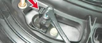
Knock sensor
The knock sensor (DS) is designed to save fuel and increase engine power. It consists of a piezoelectric element that generates electricity when detonation occurs, thereby regulating its level. As the oscillation frequency increases, the voltage supplied to the electronic control unit increases. The DD adjusts the ignition settings to optimize the ignition process in the cylinders of the fuel-air mixture.
Knock sensor location
On VAZ cars, the DD is located on the power unit block between the second and third cylinders. It is installed only on engines with a contactless ignition system and control unit. On VAZ models with contact ignition there is no DD.
Signs of a malfunctioning knock sensor
A malfunction of the knock sensor manifests itself as follows.
If any of these symptoms occur, a DD check will be required.
Checking the knock sensor
DD is checked using a multimeter. First you need to check whether the value of its resistance corresponds to the values regulated by the manufacturer. If the values differ, replace the DD. The check can be performed in another way. For this:
Video: checking the knock sensor
Prerequisites for failure
In situations where there is a malfunction, VAZ 2107 owners replace the spark plugs. Old factory spark plugs are usually replaced with iridium spark plugs from NGK or Denzo. Do not forget that only those spark plugs that are designed for the appropriate type of injection are suitable here.
The type of ignition system is no less important in determining the parameters of the spark plug. Often such manipulation does not provide much improvement (plugs have a fairly long service life), so the non-contact ignition system undergoes a full diagnosis.
Diagnostics of how the ignition module and each individual coil operates is carried out using a special device called a multimeter or ohmmeter. Its functional task is to show the voltage value supplied by the ignition module. As a result of diagnostics, it is possible to identify the source of current loss in the circuit and, accordingly, the nature of the malfunction. To facilitate painstaking work, it is recommended to dismantle the module outward before starting the process.
Non-contact ignition system checks for short circuits
First, pay attention to the coil winding. To get started, connect a multimeter, which determines the resistance value
There is a recommendation regarding the lubrication of the tip of a high-voltage wire: a special product for the VAZ 2107 or technical petroleum jelly is used here.
- the module is disconnected from the tips;
- one terminal of the device is connected to the central contact, which has a coil;
- the other terminal of the device is connected to ground.
The process of checking the secondary windings of the module includes:
Here we focus on an indicator whose value will be no less than 7 ohms. Recommendation: if at least one coil does not meet the specified indicator, the module as a whole must be replaced, otherwise it will not be possible to avoid a malfunction of the system with a VAZ 2107, where an injector is used.
The ignition coil of the VAZ 2107 is located in the engine compartment on the left side of the engine and is secured to the body with two nuts. The ignition coil is an independent element of the vehicle's electrical equipment that converts low voltage current into high voltage current up to 10-20 kV, which should be sufficient to break the gap on the spark plugs and sufficient to ignite the combustible mass. The coil is non-separable, which means that if it fails, it cannot be repaired and must be replaced with a new one.
The ignition coil is a transformer consisting of an internal magnetic circuit, primary and secondary windings, as well as an external magnetic circuit connected to the ignition distributor.
To remove the coil you will need a ten and eight wrench, also disconnect the battery.
- Disconnect the central magnetic circuit from the coil.
- Unscrew the two nuts securing the power wires with a wrench.
- Using a ten-socket wrench, unscrew the two nuts securing the coil to the car body, remove the ground wire and remove the coil from the studs.
At this point, work on removing the ignition coil of the VAZ 2107 is completed. Before replacing it with a new one, you need to make sure that it is not working; for this you will need a multimeter. Before checking, thoroughly clean the primary winding leads on the coil body (two studs to which the power wires are attached) from dirt and oxides.
- First, let's check the resistance of the primary winding. To do this, connect the ohmmeter terminals to the terminals of the primary winding (two pins on the body) and take measurements. Depending on the type of coil being tested, the resistance should be: B-117A = 3-3.5 Ohm; 27.3705 = 0.45-0.5 Ohm.
- Now we check the resistance in the secondary winding circuit. To do this, we connect one ohmmeter probe to the terminal of the high-voltage wire, and leave the second at the terminal of the primary winding. The resistance should be equal: B-117A = 7.4-9.2 kOhm; 27.3705 = 5-0.5 kOhm.
At this point, the repair work on removing and checking the ignition coil of the VAZ 2107 is completed. If, after checking, deviations from the norm are found, it is recommended to replace the coil with a new one.
Sources
- https://semerkavaz.ru/ehlektrooborudovanie/zamena-i-regulirovka-modulya-zazhiganiya-na-vaz-2107/
- https://autodont.ru/system-of-ignition/rabota-s-modulem-zazhiganiya
- https://remont-vaz2106.ru/katushka-zazhiganiya-vaz-2107
Display Guide
So, we figured out where the VAZ module and ignition coil are located and what functions they perform, now let’s talk about setting them up. If the system torque is set incorrectly, this will cause increased gasoline consumption, as well as detonation of the power unit (the “fingers” will start knocking). In general, the operation of the motor will be unstable.
To set up the ignition of a VAZ 2107, you need to perform several steps, all of them are described in detail below:
- First, you need to correctly adjust the gap that exists between the interrupter device. To do this, you should dismantle its cover in advance and clean the contact surface. At the same stage, it is necessary to check the connection of the contacts - the elements must come into contact over the entire surface, and not just in certain areas. If the contacts are poorly connected, you should try to bend them slightly. You can also try sharpening the plane a little.
- Having done this, we move on to an important stage. You need to turn the crankshaft until the contacts open as much as possible. Using a feeler gauge, you need to increase the gap to approximately 0.45 mm. It should be noted that during this, the probe between the contacts should move with low resistance.
- The crankshaft rotates until the “ignition timing” mark marked on the pulley itself. Having done this, a voltmeter should be connected to the terminal of the interrupting mechanism; if it is not there, a regular test light can be used. We are talking directly about the breaker terminal, which is connected to the coil. Using a 13mm wrench, you need to slightly loosen the nut securing the breaker to the BC.
- After these steps, you need to turn the key in the lock, but do not start the engine; at the same time, the breaker body must be turned counterclockwise. When you notice that the light has gone out, you need to start turning the housing in a different direction until the light comes on again. If the control light is on, this indicates that the moment of spark transmission through the high-voltage wires has been set. Once the torque has been established, the breaker fixing nut should be tightened until it stops.
As for checking, this is easy to do. When the car is traveling at a speed of 40 km/h, you need to press the gas so that the vehicle quickly gains power. During rapid acceleration, a brief detonation should occur until the car can accelerate to 60 km/h. If this is so, then the moment was set correctly and for some time you can forget about this procedure.
Sorry, there are no surveys available at this time.
Troubleshooting
The first sign of loss of vacuum booster seal is not deterioration of the brakes, as many sources on the Internet describe the malfunction. When air just begins to leak through the leaky membrane, the VUT continues to function properly, since the motor manages to maintain a vacuum in the front chamber. The first symptom is changes in the operation of the engine itself:
- due to air leaks into the third cylinder, the engine begins to “trouble” at idle;
- crankshaft revolutions “float”, the stronger the suction, the greater the amplitude of oscillations;
- a running engine reacts to the brake pedal and stalls when pressed sharply;
- Gasoline consumption increases.
Air leaking into the engine through the VUT causes the third cylinder to turn off - the engine begins to “trouble.”
If the car owner ignores the primary symptoms, the situation gets worse - the pedal becomes harder and requires more physical effort to slow down and stop the car. The car can be used further; a breakdown of the VUT does not lead to a complete failure of the brakes, but it significantly complicates driving, especially if you are not used to it. Emergency braking will become a problem.
How to make sure that the vacuum booster is leaking:
- Loosen the clamp and remove the vacuum pipe from the fitting on the manifold.
- Plug the fitting with a tight homemade plug.
- Start the engine. If the revs level out, the problem clearly lies in the amplifier.
- Remove the high voltage wire and remove the spark plug for cylinder III. If the VUT fails, the electrodes will be smoked with black soot.
Whenever possible, I use the old “old-fashioned” method - I simply pinch the vacuum hose with pliers while the engine is running. If the third cylinder starts working and idle speed is restored, I proceed to checking the brake booster.
Similarly, the problem can be temporarily fixed while on the road. Disconnect the pipe, plug the fitting and calmly go to the garage or service station - the power unit will operate smoothly, without excessive fuel consumption. But remember, the brake pedal will become hard and stop responding instantly to light pressure.
Additional diagnostic methods:
- Press the brake 3-4 times and start the engine while holding the pedal. If it does not fail, the valve has probably failed.
- With the engine not running, disconnect the hose from the fitting, remove the check valve and firmly insert a pre-compressed rubber bulb into the hole. On a sealed amplifier it will retain its shape, on a faulty amplifier it will fill with air.
Using a bulb, you can accurately determine the location of the defect, but the vacuum booster will have to be removed. While pumping air into the chamber, wash the edges of the joints and the stem seal - bubbles will indicate the location of damage.
Causes of clogging of the distributed injection system
One of the faults, a clogged injector, can be repaired with your own hands. The cause of the blockage is the use of low-quality gasoline. The lower the quality of the fuel, the more heavy paraffins it contains. They are deposited on the walls of the fuel system, clog the injector openings, making it difficult to supply fuel.
In addition, paraffins are deposited on the exhaust valves, which leads to their burnout. The engine begins to detonate.
To prevent this from happening, you need to use high-quality gasoline with special additives. But if clogging cannot be avoided, you can wash it yourself using a special flush of injection systems.
To rinse, you must have a syringe and rinsing liquid.
Mix the liquid with gasoline in the proportion indicated in the instructions on the bottle. We fill it into the fuel distribution system through the hose fitting of the vacuum brake booster. First we do this with the engine not running. Then we start it and add the mixture in small portions. This helps break down paraffin deposits. Under the influence of washing, paraffin deposits dissolve, enter the cylinder, burn and come out along with the exhaust gases. In this case, black smoke may come out of the exhaust pipe.
Ignition coil design
Almost all ignition coils on VAZ cars are conventional step-up transformers equipped with two windings - primary and secondary. Between them is a massive steel core. All this is placed in a metal case with insulation. The primary winding is made of copper wire coated with varnish insulation. The number of turns in it can vary from 130 to 150. It is this winding that is supplied with an initial voltage of 12 volts.
The design of the ignition coil on the VAZ 2107 cannot be called complex
The secondary winding is located on top of the primary. The number of turns in it can reach 25 thousand. The wire in the secondary winding is also copper, but its diameter is only 0.2 mm. The output voltage supplied to the spark plugs from the secondary winding reaches 35 thousand volts.
Types of ignition coils
Over the years, different types of ignition coils were installed on VAZ cars, which differed in design:
- common coil. One of the earliest devices that was installed on the very first G7s. Despite its venerable age, the coil is still installed on the VAZ 2107 today. The design of the device was described above: two copper windings on top of a steel core;
- individual reel. It is mainly installed on cars with electronic ignition systems. In these devices, the primary winding is also located inside the secondary, but individual coils are installed on all 4 VAZ 2107 spark plugs;
- twin coils. These devices are only used on vehicles with electronic ignition systems. These coils differ from all others in the presence of double wires, thanks to which the spark is supplied not to one, but to two combustion chambers at once.
Location and connection diagram
The ignition coil on VAZ 2107 cars is located under the hood, near the left mudguard. Attached with two long studs. A rubber cap with a high-voltage wire is connected to it.
The ignition coil on the VAZ 2107 is located under the hood on the left, near the mudguard
The coil is connected according to the diagram below.
The connection diagram for the VAZ 2107 ignition coil is not particularly complicated
Setting the ignition timing
The ignition system is a very sensitive unit that requires careful adjustment. Only in this case can you achieve optimal engine performance, minimum fuel consumption and maximum possible power.
Methods for setting the ignition angle
You can adjust the ignition timing in different ways.
The choice of method depends primarily on the availability of the necessary equipment and available tools.
Adjusting the ignition by ear
This method is distinguished by its simplicity, but it is recommended only for experienced car enthusiasts. The work is carried out with the engine warm and running in the following sequence.
Adjusting the ignition using a light bulb
You can adjust the ignition of the VAZ 2107 using a 12V light bulb (car “control”). This is done as follows.
Video: adjusting the ignition using a light bulb
Adjusting the ignition using a strobe light
Connecting the strobe and setting the ignition timing is carried out in the following order:
Video: adjusting the ignition using a strobe light
The operating order of the VAZ 2107 engine cylinders
The VAZ 2107 is equipped with a gasoline, four-stroke, four-cylinder, in-line engine with an overhead camshaft. In some cases, to diagnose and troubleshoot problems, it is necessary to know the operating sequence of the cylinders of the power unit. For the VAZ 2107, this sequence is as follows: 1 - 3 - 4 - 2. The numbers correspond to the cylinder numbers, and the numbering starts from the crankshaft pulley.
Setting the slider direction
With properly adjusted ignition, the engine and ignition system elements must be set in accordance with certain rules.
Thus, adjusting the ignition timing of the VAZ 2107 is quite simple. Even an inexperienced car enthusiast with a minimum set of tools and carefully following the instructions of specialists can do this. At the same time, one should not forget about safety requirements, since most of the work involves high voltage.
Source