If the ignition coil on a VAZ 2107 fails, you will not be able to start the car. The only thing left for the driver in such a situation is to ask passing drivers to tow the car or call a tow truck. And once he gets to the garage, the driver can replace the ignition coil himself. Let's figure out how this is done.
- Ignition coil design
Types of ignition coils - Location and connection diagram
- Video: faulty ignition coil
- Test sequence
- Coil replacement sequence
Connection diagram for VAZ 2107 switch
The contactless ignition system of the VAZ 2107 includes:
- Candles.
- Ignition distributor (sensor).
- Anti-interference screen.
- Non-contact slider position sensor.
- Switch that controls spark generation.
- Ignition coil.
- Assembly block.
- Ignition switch relay.
- Ignition switch on the steering column.
Wire “A” goes to the positive terminal of the car generator output. The connection diagram for the VAZ 2107 switch is shown in the figure:
Signs of a malfunction of the VAZ 2107 switch
The main symptom of a switch failure is the absence of a spark at the spark plugs. Alternatively, the spark may not be powerful enough or disappear periodically. In this case, the engine starts poorly, runs intermittently, stalls at idle, loses power, or its speed constantly fluctuates. It should be remembered that all these signs can also appear due to malfunctions of other parts of the ignition system: the Hall sensor. wires and spark plugs, ignition coil, distributor. The spark also disappears when the timing belt breaks and there is no contact in the power supply circuit of the ignition system. To accurately determine the cause, it is necessary to separately check the functionality of the switch.
What is electronic ignition
The term "electronic ignition" means the same as "contactless ignition". The BSZ unit is assembled from electronic (semiconductor) components, which is reflected in the name of the system. “Contactless” ignition is called because the closing and opening of the low-voltage circuit is carried out by an electronic switch by locking and unlocking the transistor, and not by the distributor contact.
The electronic ignition system of the VAZ 2107 for the carburetor and injection versions is different. Perhaps this is the reason for the erroneous opinion that electronic and contactless ignition are different systems.
Types of ignition systems VAZ 2107
The evolution of the VAZ 2107 has transformed the ignition system of this car from an unreliable mechanical design into a modern computer-controlled electronic system. Changes occurred in three main stages.
Contact ignition of carburetor engines
The first modifications of the VAZ 2107 were equipped with a contact-type ignition system. This system worked as follows. The voltage from the battery was supplied through the ignition switch to a transformer (coil), where it increased several thousand times, and then to a distributor, which distributed it among the spark plugs. Since voltage was pulsed to the spark plugs, a mechanical breaker located in the distributor housing was used to close and open the circuit. The breaker was subjected to constant mechanical and electrical stress, and it often had to be adjusted by setting the gaps between the contacts. The contact group of the device had a short resource, so it had to be changed every 20–30 thousand kilometers. However, despite the unreliability of the design, cars with this type of ignition can still be found today.
The contact ignition system requires adjustment of the gap between the breaker contacts
Contactless ignition of carburetor engines
Since the beginning of the 90s, a contactless ignition system was installed on carburetor VAZ 2107, where the breaker was replaced with a Hall sensor and an electronic switch. The sensor is located inside the ignition distributor housing. It reacts to the rotation of the crankshaft and sends a corresponding signal to the switching unit. The latter, based on the data received, supplies (interrupts the supply) voltage from the battery to the coil. Then the voltage returns to the distributor, is distributed and goes to the spark plugs.
In the contactless ignition system, the mechanical breaker is replaced by an electronic switch
Contactless ignition of injection engines
The latest VAZ 2107 models are equipped with electronically controlled injection engines. The ignition system in this case does not provide any mechanical devices at all, not even a distributor. In addition, there is no coil or commutator as such. The functions of all these components are performed by one device - the ignition module.
The operation of the module, as well as the operation of the entire engine, is controlled by the controller. The principle of operation of such an ignition system is as follows: the controller supplies voltage to the module. The latter converts the voltage and distributes it among the cylinders.
Description of SZ on UAZ
How is the ignition circuit installed, configured and adjusted on the AUZ 417 or any other? We will talk about this below. But first, let's understand the principle of operation of the node, as well as the types of SZ.
Operating principle of SZ
As already said, the ignition on an UAZ performs one of the main functions when starting the power unit. Thanks to this system, the procedure for igniting the air-fuel mixture in the cylinders of the power unit is carried out by supplying a spark. The spark is directly supplied to the spark plugs; one spark plug is installed on each cylinder. All of these safety devices operate in sequence mode, igniting the combustible mixture in the required period of time. It is also necessary to take into account that the ignition system on cars not only provides a spark, but also determines its strength.
The vehicle battery is not able to produce the voltage and current required to ignite the mixture, since this device only produces a certain amount of current. The help comes from the ignition system, the purpose of which is to increase the power of the car’s battery. As a result of using the SZ battery, it is possible to transmit sufficient voltage to the spark plugs to ignite the mixture.
Types of ignition systems
Today there are three main types of ignition systems that can be installed on cars:
- Contact SZ. It is considered obsolete, but continues to be successfully used on domestically produced vehicles. The principle of operation is that the system produces the necessary impulse, which appears due to the operation of the distribution component. The contact-type device itself is simple, and this is a plus, because in the event of a breakdown, the driver can always diagnose and repair it himself. The cost of replacement components is not high. The main components of a contact type system are a battery, a short circuit, a drive, spark plugs, a capacitor, and a breaker with a distributor.
- A non-contact ignition system called transistor. Many vehicles are equipped with this type. When compared with the type described above, the system is characterized by a number of advantages. Firstly, the generated spark has greater power, which is due to the increased voltage level in the secondary winding of the ignition coil. Secondly, the contactless system is equipped with an electromagnetic device that allows for stable operation, as well as energy transfer to all nodes. As a result, with proper tuning of the internal combustion engine, this allows not only to increase operating power, but also to save fuel. Thirdly, it is convenient in terms of node maintenance. To ensure long-term performance, after setting up and installing the distributor drive, this element must be lubricated from time to time. To ensure normal operation, the element is lubricated every ten thousand kilometers. As for the disadvantages, it is the difficulty of repair. It is impossible to repair the device yourself; this requires special diagnostic equipment, which is only available at service stations.
- Another option for SZ is electronic, which is the most technologically advanced and expensive today, which is why new vehicles are equipped with it. Unlike the two systems described above, the electronic ignition system is characterized by a complex device that ensures the functionality of not only the torque, but also other parameters. Currently, all modern cars are equipped with electronic systems. The key advantage is a more simplified procedure for setting the advance angle, as well as the absence of the need to periodically check the contacts for oxidation. In practice, the air-fuel mixture in engines with electronic combustion almost always burns completely. This type also has its disadvantages, in particular in the matter of repairs. It is impossible to produce it with your own hands, since this requires equipment. Detailed instructions for adjusting the ignition using a light bulb are presented in the video below.
Distributor
The ignition distributor (distributor) is designed to transmit high-voltage current pulses that come from the coil to the spark plugs. The distributor consists of:
- aluminum body;
- shaft;
- Hall sensor;
- vacuum and centrifugal ignition timing regulators;
- runner;
- covers with four fixed contacts.
In “sevens” with contactless ignition, distributors of type 38.3706 are used.
A Hall sensor is installed on the distributor 38.3706
Table: technical characteristics of distributor type 38.3706
| Characteristics | Indicators |
| Supply voltage, V | 12 |
| Permissible speed, rpm | 3500 |
| Switching on the centrifugal regulator at, rpm | 400 |
| Maximum angle of the centrifugal regulator, o | 15,5 |
| Turn on the vacuum regulator at, mm. Hg Art. | 85 |
| Maximum angle of the vacuum regulator, o | 6 |
| Operating temperature range, oС | -40 — +100 |
| Weight, kg | 1,05 |
Where is the distributor located in the VAZ 2107
The ignition distributor is mounted on the left side of the engine cylinder block. Its shaft is driven by the auxiliary drive gear. The number of revolutions of the distributor shaft directly depends on the speed of rotation of the crankshaft.
The distributor is located on the left side of the cylinder block
Malfunctions of the VAZ 2107 distributor and their symptoms
The most common breakdowns of the “seven” distributor include:
- burning of the fixed contacts of the cover;
- mechanical damage or electrical breakdown of the cover;
- burning of the runner.
As for the symptoms, for the listed problems they will be similar:
- unstable engine operation;
- reduction in power characteristics of the power plant;
- increased fuel consumption.
To diagnose major distributor failures, it does not need to be removed from the engine. It is enough to disconnect the high-voltage wires from the cover and unfasten the two latches that secure it to the body. By removing the cover and inspecting the contacts with the slider, you can visually assess their condition and draw a conclusion about how suitable they are for further work. If the contacts cannot be cleaned, the device cover must be replaced. Such a part costs about 200 rubles. The runner will cost half as much.
The distributor cover is attached to its body using two latches
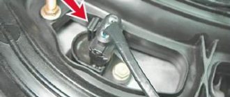
Knock sensor
The knock sensor (DS) is designed to save fuel and increase engine power. It consists of a piezoelectric element that generates electricity when detonation occurs, thereby regulating its level. As the oscillation frequency increases, the voltage supplied to the electronic control unit increases. The DD adjusts the ignition settings to optimize the ignition process in the cylinders of the fuel-air mixture.
Knock sensor location
On VAZ cars, the DD is located on the power unit block between the second and third cylinders. It is installed only on engines with a contactless ignition system and control unit. On VAZ models with contact ignition there is no DD.
The knock sensor is located on the engine block between the second and third cylinders
Signs of a malfunctioning knock sensor
A malfunction of the knock sensor manifests itself as follows.
- Acceleration dynamics deteriorate.
- The engine "troits" at idle.
- During acceleration and at the beginning of movement, the CHECK indicator lights up on the instrument panel.
If any of these symptoms occur, a DD check will be required.
Checking the knock sensor
DD is checked using a multimeter. First you need to check whether the value of its resistance corresponds to the values regulated by the manufacturer. If the values differ, replace the DD. The check can be performed in another way. For this:
- Set the multimeter to voltmeter mode in the “mV” range and connect the probes to the sensor contacts.
- They hit the DD body with a hard object and look at the readings of the device, which, depending on the force of the blow, should vary from 20 to 40 mV.
- If the DD does not respond to such actions, it is replaced with a new one.
Instructions for setting the ignition
If you strictly followed the instructions, connected all the wires according to the diagram and did not misalign the marks, then the motor will start without problems. To adjust the ignition, you need to ensure stable engine operation, so first warm it up for a few minutes, without letting it stall by pressing the gas pedal.
Adjustments can be made on a warm engine using two methods:
- without the use of special devices - “by ear”;
- fine adjustment using a strobe light.
A strobe is a device with a light bulb that flashes simultaneously with the transmission of a pulse by the Hall sensor. When the switched on strobe is brought to the crankshaft flywheel with the engine running, the position of the notch becomes visible. Hence the possibility of precise adjustment.
This is what a strobe looks like for fine-tuning the ignition
To set up, connect the strobe power supply to the battery, and the thick wire to the high-voltage wire of the spark plug of the 1st cylinder. Loosen the distributor fastening nut and bring the flashing lamp to the pulley. Slowly turn the distributor body until the notch on the pulley aligns with the short notch, then tighten the nut.
Tuning in the traditional way “by ear” is done like this:
- Start the engine and loosen the nut holding the ignition distributor.
- Rotate the distributor smoothly and slowly within 15°. Find the position at which the motor operates most stably.
- Tighten the fastening nut.
When adjusting, turn the distributor by the membrane body
It is quite natural that after installing a contactless ignition system, the engine idle speed will increase to 1100-1200 rpm due to the increased spark power. Set the rate to 850-900 rpm by tightening the idle screw on the carburetor and using the tachometer as a guide. On VAZ 2105-2107 carburetors of the “Ozone” type, this screw is located in the lower section of the unit on the right side and is large in size. The VAZ 2108 carburetors of the Solex type (these were also installed on the “seven”) have a long plastic handle protruding from the right (in the direction of travel). The second screw, which regulates the composition of the air-fuel mixture, cannot be turned.
The arrow shows the idle speed adjustment screw.
Setting the ignition timing with advance
This setup is completely easy to do. Even a beginner can cope with this task. To do this, prepare a 13 mm wrench and a special 38 mm crankshaft wrench in advance.
If your car is started, be sure to turn off the engine, since you can only turn on the ignition when the engine is turned off. First, the piston of the first cylinder is installed at the top dead center of the compression stroke, that is, in the ignition position. Before doing this, remove the candles and plug the hole from them with cotton.
You need to align the mark on the crankshaft and the front engine cover. To do this, use a wrench to start turning the crankshaft clockwise. During this action, the air compressed there should push out the cotton wool, thereby indicating the compression stroke. Continue turning the shaft slowly until the marks on the timing belt pulley and cover line up.
Please note that there are 3 marks on the cover:
- The first indicates ignition advance by 10º;
- the second – by 5 º;
- the third is equal to zero.
Since a VAZ 2107 engine with a carburetor runs on 92 or 95 gasoline, we need to set the ignition for these types of fuel. That is why you should select the second mark, which will indicate an ignition advance of 5º.
Once the required parameters match, put the spark plugs in place and remove the wires. The system is ready for use.
How to carry out repairs
If a breakdown is detected, the damaged coil must be removed. To complete the work you will need a set of wrenches.
Removing the module
To remove a faulty unit, you will need:
- Disconnect the battery from the on-board network and remove the air filter housing.
- Disconnect the high-voltage cables and wiring harness.
- Remove the 3 nuts that hold the assembly to the mounting pad.
Replacement features
You can install the coil without using a special tool. The ignition system of injection engines does not require any adjustments. The throttle position is adjusted in idle and maximum gas modes. In case of malfunctions, it is necessary to check and align the crankshaft position sensor to the marks on the drive pulley of external units.
https://youtube.com/watch?v=h-b_85f0QMI
Carrying out repairs
The module is repaired if it is not possible to buy a new product. The lower part of the case is opened, and then the damaged tracks are restored. It is impossible to repair the coils in artisanal conditions; the parts are not supplied to the spare parts market. To perform installation work, soldering equipment and skills in working with equipment are required. Rebuilding ignition coils is not recommended.
Ignition adjustment
The injection modification of the VAZ 2107 does not require adjustment of the ignition timing. The electronic control unit, using a sensor, determines the optimal ignition timing. The participation of the car owner in adjusting the operation is limited to setting the engine timing belt to the marks.
To check the performance of the ECU and the functionality of the sensors, it is necessary to connect a computer with specialized software. In this way, the cause of most electronic ignition system malfunctions can be determined.
It is also worth checking the operation of the throttle position sensor yourself. When the throttle is closed, the voltage on the sensor should be no higher than 0.55 volts, and when fully open - 4.5 volts. Measurements must be made with a voltmeter with the ignition on.
The process of replacing spark plugs
Required tools and materials:
- Spark plug head 16 mm;
- Spark plug head 21 mm;
- Candle tube;
- Clean rags.
Step-by-step instructions for replacing spark plugs in a Chevrolet Niva:
- Open the hood of the vehicle.
- Remove high voltage wiring. If necessary, take a photo or note the sequence of wire installation.
- Using a feeler gauge, check the gap between the spark plug electrodes.
- Check the gap of the new spark plugs.
- Screw the new parts back in with a torque of 31-39 Nm (the order in which the spark plugs are installed does not matter).
- Install the ignition wires in the same sequence as removal.
The procedure for replacing spark plugs on a Chevrolet Niva has been completed.
How to install electronic (contactless) ignition
The sequence of installation of electronic ignition components is not particularly important. We can advise you to start by replacing the distributor:
- disconnect high-voltage wires;
- remove the distributor cover;
- rotating the crankshaft, set the slider perpendicular to the engine axis so that it is easy to repeat when installing a new distributor and mark the position of the middle mark of the distributor scale (these actions will facilitate subsequent adjustment of the electronic ignition);
- unscrew the nut securing the distributor and dismantle it;
- install a non-contact sensor-distributor instead of the old distributor, placing the slider and housing in positions corresponding to the previously applied marks;
- put on the distributor cover;
- install high-voltage wires.
Then the coil should be replaced. The operation is simple, but you need to take into account the position of contacts “B” and “K”. If it is different on the new coil, you need to rotate it relative to the fasteners so that the contacts are positioned similarly to the old one.
About the drive mechanism
To transmit torque to the distributor shaft on the “six”, a helical gear is used, rotated by a timing chain (in common parlance – “hog”). Since the element is located horizontally and the distributor roller is vertical, there is an intermediary between them - the so-called fungus with oblique teeth and internal slots. This gear simultaneously turns 2 shafts - the oil pump and the distributor.
The distributor drive consists of two transmission gears with oblique teeth
Both transmission links - the “hog” and the “fungus” - are designed for a long service life and are replaced during engine overhauls. The first part is removed after disassembling the timing chain drive, the second is pulled out through the upper hole in the cylinder block.
The VAZ 2106 distributor, equipped with a contact breaker, is a rather complex unit consisting of many small parts. Hence the unreliability of operation and constant failures of the spark generation system. The non-contact version of the distributor creates problems much less frequently, but in terms of performance characteristics it still falls short of modern ignition modules, which have no moving parts.
REPLACING THE DEVICE
If the indicators do not correspond to the above values, the ignition coil is considered faulty. Such a device must be replaced with a working one, which can be purchased at almost any spare parts store. When purchasing the device, you must inspect it and check the availability of documents: technical passport and certificate.
Removing the ignition coil on a VAZ2107 car is carried out with the battery disconnected. Use a wrench to unscrew the nuts on the contact and mounting studs. The faulty device is removed. A spare part is installed in its place and secured and connected. Now you can connect the battery and start the engine.
Sources
- 7vaz.ru/remont/diagnostika-i-zamena-katushki-zazhiganiya.html
- autocentrum.ru/brands/lada/17209-obzor-sistemy-zazhiganiya-vaz-2107-katushki-i-drugih-elementov-posobie-po-vystavleniyu.html
- drive2.ru/l/487397562748240344/
- 21074.ru/elektrooborudovanie/kak-proverit-modul-zazhiganija-vaz-2107-inzhektor-multimetrom/
- bumper.guru/klassicheskie-modeli-vaz/elektrooborudovanie/zazhiganie/zazhiganie-2107/katushka-zazhiganiya-vaz-2107.html
Ignition module
The ignition module is a device designed to convert DC voltage from the on-board network into electronic high-voltage pulses with their subsequent distribution among the cylinders in a certain order.
In the injection VAZ 2107, the ignition module replaced the coil and switch
Design and operating principle
The design of the device includes two two-terminal ignition coils (transformers) and two high-voltage switches. The voltage supply to the primary windings of the transformer is controlled by the controller based on the information received from the sensors.
The operation of the ignition module is controlled by the controller
In the ignition system of an injection engine, voltage distribution is carried out according to the idle spark principle, which provides for the pairwise division of cylinders (1–4 and 2–3). A spark is formed simultaneously in two cylinders - in the cylinder in which the compression stroke is coming to an end (working spark), and in the cylinder where the exhaust stroke begins (idle spark). In the first cylinder, the fuel-air mixture ignites, but in the fourth, where the gases burn out, nothing happens. After turning the crankshaft half a turn (180), the second pair of cylinders enters the process. Since the controller receives information about the exact position of the crankshaft from a special sensor, problems with sparking and its order do not arise.
Location of the ignition module VAZ 2107
The ignition module is located on the front side of the cylinder block above the oil filter. It is secured to a specially designed metal bracket using four screws. It can be identified by the high-voltage wires coming out of the housing.
The ignition module is located on the front of the cylinder block above the oil filter
Factory designations and characteristics
VAZ 2107 ignition modules have catalog number 2111–3705010. As an alternative, consider products numbered 2112–3705010, 55.3705, 042.3705, 46.01. 3705, 21.12370–5010
They all have approximately the same characteristics, but when purchasing a module you should pay attention to the engine size for which it is intended
Table: technical characteristics of the ignition module 2111–3705010
| Name | Index |
| Length, mm | 110 |
| Width, mm | 117 |
| Height, mm | 70 |
| Weight, g | 1320 |
| Rated voltage, V | 12 |
| Primary winding current, A | 6,4 |
| Secondary winding voltage, V | 28000 |
| Duration of spark discharge, ms (not less) | 1,5 |
| Spark discharge energy, MJ (not less) | 50 |
| Operating temperature range, C | from -40 to + 130 |
| Approximate price, rub. (depending on manufacturer) | 600–1000 |
Briefly about ignition
Before installing the BSZ, it is worth checking the condition of the high voltage cables and spark plugs. We remove the distributor cover and manually turn the crankshaft until the slider is turned towards the first cylinder on the distributor, and the mark on the shaft pulley and the middle mark on the timing cover are approximately the same. The permissible gap between the spark plug electrodes is checked with a probe.
By pointing the lamp at the pulley, you see the position of the mark and its change as the speed increases. The battery supplies the generator with electric current and starts the engine.
With a small current in the system, this is not life-threatening, but an electric shock can be very sensitive. Let's assume that compression occurs in the first cylinder and a spark is needed for ignition, and in the fourth cylinder there is a purge phase and an idle spark is formed there.
Its value depends on the crankshaft speed and the load on the power unit. In this case, the device will show the resistance of the primary winding. The author of the video is altevaa TV. Because of this, high voltage appears in the winding of the secondary ignition coil, reaching the spark plug of the required cylinder. Malfunctions If the ignition coil is faulty, the engine will not start. The price of a new such part is about rubles, or even a little cheaper. Judging by the readings of the device, my case shows and confirms again that everything is fine with the coil. When conducting an external inspection, it is necessary to test the product body for the presence of dirt and dust deposits, oil leaks, surface integrity and the stability of connections and contacts of electrical wiring. We spread the ignition wires
Checking the ignition coil
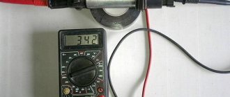
The coil is checked based on two indicators: the presence of a short circuit and an open circuit. Before diagnostics, the ignition coil must be disconnected. After this, one probe of the device is connected to the central contact of the coil, the second to the body (ground). If the display shows resistance equal to infinity, there is no short circuit.
The primary winding of the coil for a break occurs differently. The probes of the device must be connected to the right and left contacts. The resistance between them should be within 3-3.5 Ohms.
If the resistance of the primary winding does not correspond to the norm or there is a short circuit in the coil to the housing, it must be replaced.
A little theory.
The ignition coil on cars is necessary to convert a low voltage current of 12 V into a high current - 11-20 kV, which is necessary to create a spark at the spark plugs. What happens next is probably known to everyone!? The spark ignites the working mixture and a release of energy occurs, which sets the pistons in motion. As I said in my previous articles, the ignition coil is a kind of transformer, which can also be called a miniature automotive “substation”.
On the “seven”, as a rule, contact ignition systems of the B-117 A type are used. The coil itself is located in the engine compartment and is attached to the left mudguard with two studs. Also found on the VAZ 2107 are non-contact ignition systems (BSZ), in this case, coils of type 27.3705 are used, oil-filled with an open magnetic circuit, as well as type 3122.3705 dry coils with a closed magnetic circuit.
How to check the ignition of a VAZ 2106 with a multimeter
In order to check the coil with a multimeter, we need the multimeter itself and, of course, the ignition coil itself. take a multimeter and set it to 200-ohm, then check the terminals (B - K), the resistance should be at least in the range of 04.0-ohm, the resistance range is from 03.8 to 04.5-ohm, this is the norm; there’s clearly something wrong with the coil; now we need to check the high-voltage part; we set it measurement mode 20-klom 1 any probe on mark B or K another on the high-voltage contact resistance 7.6 klom 7 to 8 klom this is the norm This means your coil is intact, but also do not forget that there may be an internal breakdown of the coil, that is, a breakdown of the insulation between the high-voltage and low-voltage winding and also the interturn one, and you also need to check the case, that is, also at 20 kL, we leave the relative mass for each contact, we check because we came across coils, so we check everything is fine on the case, it breaks through, and if there are no short circuits between the winding and interturn circuits, then it will function.
“In the VAZ 2107, the injector does not get a spark to the spark plugs, what is the reason? Does anything depend on the spark plugs?
“In the VAZ 2107, the injector does not get a spark to the spark plugs, what is the reason? Does anything depend on the spark plugs?
- don’t touch his brains, he has nothing to do with them
Remove the wire completely from the spark plug and the coil - perhaps the mechanics placed an acid plug and the wire was destroyed! Check everything - one by one - so as not to mix it up! Good luck! Look for oxides and rust on the reel. And check your connection. Power will be supplied to the ignition module, as well as to the injectors, immediately when the ignition is turned on. If not, you need to look at the main fuses of the control system. They are located under the glove compartment shelf (if you bend over, you can see them). There are three fuses and three relays. Main relay, fuel pump relay and cooling fan relay. Nearby, respectively, are their fuses. Of course, first you need to check whether there is power to the fuses themselves. It should always be there, regardless of the ignition switch. If the fuses are OK, check whether one of the relays (the main one) clicks when the ignition is turned on. If it clicks, check the voltage at the relay output (it happens that although it clicks, the contacts in the nm do not close). If it does not click, check the voltage on the relay coil (you can use a light bulb). If not, check the circuit from the lock to the ECU and from the ECU to the relay. If there is no connection from the ECU to the relay, remove and install the ECU connector, at the same time inspecting the contacts for moisture, traces of oxidation, etc. If there is no connection from the lock to the ECU, look at the circuit, lock, and signaling (if there is one). Let's say everything is ok with this. We look at the circuit from the relay to the ignition module, injectors, mass air flow sensor, IAC. If there is a relay at the output, but no further, then there is only a break. Well, or again the signal. We checked, there is some wear on the module, etc., let's check the spark. It is not advisable to break, you may be lucky, or maybe not (then the ECU is a kayak). It is better to insert a candle into the tip and securely attach it to ground. There is no spark, which means there is something wrong with the crankshaft position sensor or the circuit from it. If all other sensors malfunction, either together or separately, there will be a spark! There is a spark, but it won’t start - check the fuel. Remove the plastic cap from the ramp and hold the hole with your finger so that the nipple pin is buried in the hole and turn on the ignition (with an assistant). There the pressure is 2.5-3 atmospheres, and if everything is normal, then you can’t hold it with your finger. True, it starts with 1st atmosphere, but it works poorly. If there is no pressure, listen to see if the pump is running when the ignition is turned on (in fact, all checks begin with this). I can’t hear it, go back to the same relay and check the circuits. It's humming, check the filters, tubes (are they pinched?) tell me there is no spark VAZ 2107 injector Fuse in the brain area (it's separate, not in the block) Signal light Well, then look in the low voltage circuit (is there something coming to the module). the module itself, all the wires and spark plugs could not be covered at once
About their device
Before finding out the importance of the elements of the ignition system in question, it is necessary to understand their structure. Structurally, the high-voltage wire consists of the following parts:
- A conductor through which current flows.
- Insulation - rubber or silicone is used as an insulating material.
- Protective caps on both ends.
- Metal contacts.
Each element performs corresponding tasks, and at the slightest violation of integrity, it will be necessary to replace it. Armored wires cannot be repaired, since they play one of the main roles in the car’s ignition system, and also belong to the category of consumables.
To distributor or MZ
It is a mistaken belief that armored wires on a car are ordinary wires that are designed to transmit current from a source to a receiver. As you know, VAZ 2107 cars were produced in two variations of the fuel supply system - carburetor and injector. Although many parts and mechanisms on the carburetor and injector are the same, this does not apply to the GDP. The carburetor VVP differs from the injection one on the VAZ 2107 in the following parameters:
- The length, on which the amount of resistance also depends. The wires on the injection unit are shorter than on the carburetor.
- Fasteners that connect to the distributor on the carburetor and the ignition module on the injector.
- The amount of GDP. There are four of them on the injector, and five on the carburetor.
- Type of caps.
Knowing the design differences, you must also understand that high voltage flows through the wire. The current comes from the distributor or MG through the wires to the spark plugs. The slightest malfunctions lead to the fact that current is not supplied to the spark plug, and a spark does not occur. If a spark does not occur, the cylinder does not work, which negatively affects the operation of the engine.
Spark plug
Plugs are used to ignite the fuel-air mixture in the engine cylinders when high voltage is supplied from the ignition coil. The main elements of any spark plug are a metal body, a ceramic insulator, electrodes and a contact rod.
Spark plugs are necessary to generate a spark and ignite the fuel-air mixture in the engine cylinders
Checking spark plugs for VAZ 2107
There are many ways to check spark plugs. The most popular are the following algorithms.
- With the engine running, remove the high-voltage wires one by one and listen to the operation of the engine. If after disconnecting the wire no changes occur, then the corresponding spark plug is faulty. This does not mean that it necessarily needs to be changed. In some cases, you can get by with cleaning it.
- The spark plug is unscrewed and a high-voltage wire is put on it. The spark plug body is leaned against a mass (for example, a valve cover) and the starter is cranked. If the part is working properly, the spark will be clear and bright.
- Sometimes spark plugs are checked with a special tool - a gun. The spark plug is inserted into a special hole and checked for the presence of a spark. If there is no spark, the spark plug is faulty.
- Candles can be checked with a homemade device made from a piezo lighter. The wire from the piezo module is extended and attached to the tip of the candle. The module is pressed against the spark plug body and the button is pressed. If there is no spark, replace the spark plug with a new one.
Video: checking spark plugs
Selection of spark plugs for VAZ 2107
Various models of spark plugs are installed on VAZ 2107 carburetor and injection engines. In addition, the parameters of the spark plugs depend on the type of ignition system.
The choice of spark plugs for the VAZ 2107 is determined by both the ignition system and the engine type
Auto stores offer many types of spark plugs for the VAZ 2107, differing in technical characteristics, quality, manufacturer and price.
Table: characteristics of spark plugs depending on the type of VAZ 2107 engine
| For carburetor engines with contact ignition | For carburetor engines with contactless ignition | For injection 8-valve engines | For injection 16-valve engines | |
| Thread type | M 14/1.25 | M 14/1.25 | M 14/1.25 | M 14/1.25 |
| Thread length, mm | 19 mm | 19 mm | 19 mm | 19 mm |
| Heat number | 17 | 17 | 17 | 17 |
| Thermal enclosure | Stands for spark plug insulator | Stands for spark plug insulator | Stands for spark plug insulator | Stands for spark plug insulator |
| Gap between electrodes, mm | 0.5 – 0.7 mm | 0.7 - 0.8 mm | 0.9 – 1.0 mm | 0.9 – 1.1 mm |
You can install spark plugs from various manufacturers on VAZ cars.
Table: manufacturers of spark plugs for VAZ 2107
| For carburetor engines with contact ignition | For carburetor engines with contactless ignition | For injection 8-valve engines | For injection 16-valve engines |
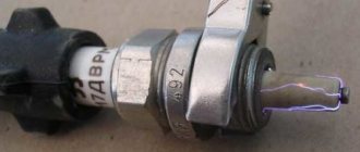
| A17DV (Russia) | A17DV-10 (Russia) | A17DVRM (Russia) | AU17DVRM (Russia) |
| A17DVM (Russia) | A17DVR (Russia) | AC DECO (USA) APP63 | AC DECO (USA) CFR2CLS |
| AUTOLITE (USA) 14–7D | AUTOLITE (USA) 64 | AUTOLITE (USA) 64 | AUTOLITE (USA) AP3923 |
| BERU (Germany) W7D | BERU (Germany) 14–7D, 14–7DU, 14R-7DU | BERU (Germany) 14R7DU | BERU (Germany) 14FR-7DU |
| BOSCH (Germany) W7D | BOSCH (Germany) W7D, WR7DC, WR7DP | BOSCH (Germany) WR7DC | BOSCH (Germany) WR7DCX, FR7DCU, FR7DPX |
| BRISK (Czech Republic) L15Y | BRISK (Italy) L15Y, L15YC, LR15Y | CHAMPION (England) RN9YC | CHAMPION (England) RC9YC |
| CHAMPION (England) N10Y | CHAMPION (England) N10Y, N9Y, N9YC, RN9Y | DENSO (Japan) W20EPR | DENSO (Japan) Q20PR-U11 |
| DENSO (Japan) W20EP | DENSO (Japan) W20EP, W20EPU, W20EXR | EYQUEM (France) RC52LS | EYQUEM (France) RFC52LS |
| NGK (Japan/France) BP6E | EYQUEM (France) 707LS, C52LS | MARELLI (Italy) F7LPR | MARELLI (Italy) 7LPR |
| HOLA (Netherlands) S12 | NGK (Japan/France) BP6E, BP6ES, BPR6E | NGK (Japan/France) BPR6ES | NGK (Japan/France) BPR6ES |
| MARELLI (Italy) FL7LP | MARELLI (Italy) FL7LP, F7LC, FL7LPR | FINVAL (Germany) F510 | FINVAL (Germany) F516 |
| FINVAL (Germany) F501 | FINVAL (Germany) F508 | HOLA (Netherlands) S14 | HOLA (Netherlands) 536 |
| WEEN (Netherlands/Japan) 121–1371 | HOLA (Netherlands) S13 | WEEN (Netherlands/Japan) 121–1370 | WEEN (Netherlands/Japan) 121–1372 |
Product delivery options
Note! Below are the shipping methods available specifically for this product. Payment options may vary depending on the delivery method.
Detailed information can be found on the “Delivery and Payment” page.
Parcel by Russian Post
Available payment methods:
- Cash on delivery (payment upon receipt)
- Using cards Sberbank, VTB, Post Bank, Tinkoff
- Yandex money
- QIWI
- ROBOKASSA
Shipping throughout Russia. Delivery time is from 5 to 12 days.
Parcel by Russian Post 1st class
Available payment methods:
- Cash on delivery (payment upon receipt)
- Using cards Sberbank, VTB, Post Bank, Tinkoff
- Yandex money
- QIWI
- ROBOKASSA
Shipping throughout Russia. Delivery time is from 2 to 5 days. More expensive than regular delivery by Russian Post, approximately 50%. Parcel weight up to 2.5 kg
Express Parcel EMS
Available payment methods:
- Cash on delivery (payment upon receipt)
- Using cards Sberbank, VTB, Post Bank, Tinkoff
- Yandex money
- QIWI
- ROBOKASSA
Shipping throughout Russia. Delivery time is from 3 to 7 days. More expensive than regular delivery by Russian Post, approximately 100%.
Methods for checking a module
If there is no spark in the ignition system, the driver can perform initial diagnostics of the module with his own hands:
Checking the ignition module.
- Place the car on the site or in the garage, turn off the engine.
- Open the hood of the car, and then remove the air filter housing with pipes.
- Unfasten the electrical wiring connector from the module.
- Turn on the ignition, and then connect the probes of the multimeter (switched to the voltage measurement mode in the range from 0 to 20 V) to the engine crankcase (minus) and the middle contact in the plug. On a working node, the parameter will be equal to 12 V; if there is no voltage or a reduced value, further diagnostics must be carried out.
- Turn off the ignition and then remove the high-voltage wires.
- Turn on the resistance measurement mode in the test equipment with a maximum value of 20 kOhm.
- Connect the probes to the outermost terminals in the connector. If the device shows infinite resistance, then there is an open circuit. In this case, the block needs to be changed.
- Check the resistance between the terminals on cylinders 1-4 and 2-3 (there are numbers on the block body that allow you to determine the purpose of the outputs). The module is considered serviceable with a resistance of 5-6 kOhm. If infinite resistance is indicated, the unit must be replaced.
The principle of operation of the ignition system of the VAZ 2106
Almost all classic models are traditionally equipped with a standard contact-type ignition system (KSZ). An exception is 21065, which uses a non-contact transistor circuit in which an interruption of the primary winding power circuit is realized using a breaker mounted in the distributor. Below we will consider in more detail how the contact ignition system of the VAZ-2106 is designed and works.
VAZ 2106 ignition system diagram
The design of the ignition contact circuit includes the following components:
- lock (switch);
- coil (short circuit);
- breaker (MP);
- distributor (MR);
- regulators, centrifugal and vacuum (CR and VR);
- candles (SZ);
- high-voltage wires (VP).
Let's take a look at the ignition coil and take a closer look at what it is needed for and what it is responsible for.
Connecting and replacing VAZ short circuit
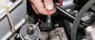
The procedure for removing and installing the ignition coil on old VAZ models:
- First, disconnect the central high-voltage wire leading to the distributor (ignition distributor).
- Disconnect all power wires from the coil contacts. Since they are fastened with nuts, you will need an 8 wrench for this.
- If you don’t know which wires to connect to which connector later, it’s better to immediately remember or mark them somehow, so that later during installation you can connect them correctly.
- Unscrew the coil housing. It is attached to a clamp (clamp), which is pressed to the car body with two nuts.
- After the work has been done, you can remove the ignition coil and replace it if necessary.
Signs of a faulty ignition coil
If, after turning the key in the ignition switch, you hear that the starter is turning, but the engine does not start, then, as a rule, this may mean that the ignition coil is not working correctly or has failed. Although there are many reasons why the engine does not start when you try to start it: spark plugs, explosive wires, problems in the fuel system (pump, fuel filter, clogged line), and so on...
But if, after all, the reason is in the ignition coil, then this can be understood by the following symptoms:
- There is no spark at the spark plugs;
- There is no current on the BB wires;
- Visual defects (cracks and chips on the reel body);
- A burning smell under the hood, which leaves traces of melting of the ignition coil (the primary or secondary winding has burned out).
Contactless ignition of vases (2101-2107). complete installation guide - AutoSovet
Now almost all classic owners install contactless electronic ignition (BSI) on their cars. And it's easy to explain. BSZ has obvious and proven advantages, such as simplicity and ease of configuration.
If you are already quite tired of the fact that the contact pair, for certain reasons, very often does not work or even fails.
You have not yet decided whether to buy a contactless ignition kit, then this article will help you make the right choice.
Now, let's move on to the most important thing - choosing and installing BSZ on your car.
I think that it is best to opt for a contactless ignition kit made in Russia, namely the city of Stary Oskol.
The box contains a coil, switch, wiring harness and distributor. This kit is considered one of the best.
For installation, we will need a drill, a drill and a pair of screws; they will be useful for installing the coil in the engine compartment; some engines have a standard mounting location, but you will have to attach the switch yourself. An open-end wrench for “13”, socket or ring wrenches for “8” and “10”, as well as a wrench for “38” are also useful.
A few words about the BZS (Contactless ignition system) VAZ 2106
The coil operating as part of a contactless circuit differs in the number of turns of the primary and secondary windings. Simply put, it is more powerful than the old version, since it is designed to create pulses of 22-24 thousand volts. The predecessor supplied a maximum of 18 kV to the spark plug electrodes.
The cable with connectors is used for reliable connection of the terminals of the ignition distributor and the switch. The structure of these two elements should be considered separately.
In terms of reliability, the BSZ is significantly superior to the outdated contact ignition of the “six”; problems arise much less frequently and are easier to diagnose.
All elements of the system are connected to each other and to the engine as follows:
- The distributor shaft rotates from the motor drive gear;
- The Hall sensor installed inside the distributor is connected to the switch;
- the coil is connected by a low voltage line to the controller, a high voltage line to the central electrode of the distributor cover;
- high-voltage wires from the spark plugs are connected to the side contacts of the main distributor cap.
The threaded clamp “K” on the coil is connected to the positive contact of the ignition switch relay and terminal “4” of the switch. The second clamp marked “K” is connected to contact “1” of the controller, and the tachometer wire also comes here. Terminals “3”, “5” and “6” of the switch are used to connect a Hall sensor.
One of the effective options is to replace the standard ignition system with a non-contact ignition system (abbreviated as BSZ), where electronics are in charge of sparking
Installation of BSZ on VAZ 2106
When choosing a contactless ignition kit, pay attention to the engine size of your “six”. The distributor shaft for a 1.3 liter engine should be 7 mm shorter than for more powerful 1.5 and 1.6 liter power units. To install BSZ on a VAZ 2106 car, you should prepare the following set of tools:
To install BSZ on a VAZ 2106 car, you should prepare the following set of tools:
- open-end or socket wrenches with dimensions of 7-13 mm;
- flathead and Phillips head screwdrivers;
- pliers;
- drill with a 4 mm drill (to mount the electronic unit in the side member you will have to make 2 holes for self-tapping screws).
I highly recommend purchasing a 38 mm socket wrench with a long handle for unscrewing the ratchet. It is inexpensive, around 150 rubles, and is useful in many situations. Using this key, it is easy to turn the crankshaft and set pulley marks to adjust the ignition and timing.
The first step is to dismantle the old system - the main distributor and coil:
- Pull out the high-voltage wires from the sockets of the distributor cover and disconnect it from the body by unlocking the latches. Dismantling old equipment begins with disassembling the distributor - removing the cover and wires
- When turning the crankshaft, set the slider at an angle of approximately 90° to the engine and place a mark on the valve cover opposite. Unscrew the 13 mm nut securing the distributor to the block. Before removing the ignition distributor, mark the position of the slider with chalk
- Unscrew the clamps of the old coil and disconnect the wires. It is advisable to remember the pinout or sketch it. The wire terminals are connected to the transformer contacts on threaded clamps
- Loosen and unscrew the nuts securing the clamp, remove the coil and distributor from the car. The distributor housing is attached to the cylinder block with a single 13 mm wrench nut.
When removing the ignition distributor, keep the washer-shaped gasket installed between the part platform and the cylinder block. It may be useful for a contactless distributor.
https://www.youtube.com/watch?v=BxzbLbvo1qc
Install the contactless kit according to the instructions:
- Remove the BSZ distributor cap and, if necessary, replace the sealing washer from the old spare part. Turn the slider to the desired position and insert the distributor shaft into the socket, lightly pressing the pad with a nut. Before installing the distributor into the socket, turn the slider towards the chalk marks drawn on the valve cover
- Replace the cover, securing the latches. Connect the spark plug cables according to the numbering (the numbers are indicated on the cover).
- Screw the coil of the contactless system to the body of the VAZ 2106. To ensure that terminals “B” and “K” are in their original position, first unfold the body of the product inside the mounting clamp. When installing the coil, connect the wires from the ignition relay and tachometer
- Place the wires from the ignition switch and tachometer onto the contacts according to the diagram above.
- Install the controller next to the spar by drilling 2 holes. For convenience, remove the expansion tank. The controller is attached to the holes in the side member using self-tapping screws
- Connect the wiring harness to the distributor, switch and transformer. The blue wire is connected to terminal “B” of the coil, the brown wire is connected to terminal “K”. Place a high-voltage cable between the distributor cover and the central electrode of the transformer. The spark plug cables are connected according to the numbering on the cover, the central wire is connected to the coil electrode
If there were no annoying mistakes during the installation process, the car will start immediately. The ignition can be adjusted “by ear” by loosening the distributor nut and slowly turning the housing at idle engine speed. Achieve the most stable operation of the motor and tighten the nut. Installation is complete.
DETAILS: Installation and repair of wipers on a VAZ 2107
The main components of the distributor and a description of its operation
VAZ classic distributor device
Device
The distributor is assembled in a housing. Inside it, a contact group is mounted on a bearing: moving and fixed contacts or a Hall sensor (for contactless ignition). To correct the advance angle, the vacuum regulator can rotate the contact group at a small angle relative to the housing. The capacitor is attached to the bottom of the case with screws. A drive roller is mounted on bushings in the center of the body. Its bottom has splines with which it engages with the drive gear. In the upper part of the roller there are contact drive cams (for contact ignition) or a steel cup with four slots - a screen (for contactless ignition). At the very top, on a steel platform, two weights and two springs of the centrifugal ignition regulator are installed. A plastic housing with a moving contact and noise suppression resistance of the high voltage distributor (slider) is screwed onto the top with two screws. The entire structure is closed with a lid on two spring latches. The body and cover have a tongue and groove so that they fit together in only one position. The cover contains contact terminals for high voltage wires from the spark plugs and from the ignition coil. The distributor is secured to the engine block using a stud, nut and pressure washer. To adjust the ignition timing, the housing can be rotated relative to the block.
Job
The distributor is connected through the drive to the engine crankshaft and rotates with it. For two full revolutions of the crankshaft, the distributor shaft makes one revolution. This is due to the fact that our engine is four-stroke. When installing the distributor in place, the roller is oriented in strict accordance with the operating order of the engine. This is done so that the contacts open and the spark jumps on the spark plug when the piston of each cylinder, compressing the combustible mixture, does not reach top dead center (TDC) by a few millimeters. This is called ignition advance. When the number of revolutions increases, the distance must be increased, and when it decreases, it must be decreased, which is what the centrifugal regulator does. Its weights, under the influence of centrifugal force, which is greater the higher the engine speed, diverge to the sides and move the cams relative to the roller, making ignition “earlier.” When the engine speed decreases, the springs return the weights to their place and the ignition becomes “later”. This is necessary to increase engine power and efficiency. In addition to the centrifugal one, a vacuum ignition timing regulator is also installed on the distributor. Its function is to fire “earlier” at low throttle opening angles and “later” at sharp throttle opening angles. At idle and at full throttle, the vacuum seal does not work. The regulators are adjusted only at the stands, so there is no need to change the settings yourself.
From the history of VAZ cars
Today, capacitor failure is an extremely rare occurrence and many do not even know about its existence. When the power supply circuit for cars was with reverse polarity, i.e., the “plus” went to ground, then not a single driver went on the road without a spare capacitor. Since 1961, by order of the Automotive Industry, they began to attach a “minus” to the ground and drivers simply forgot about the capacitor.
Let's go back to the old-style distributor...
The distributor also has centrifugal and vacuum ignition timing regulators. The centrifugal regulator is located under the slider. These are two weights with springs, which, depending on the engine speed, partially turn it inside the slider, forcing the contacts to open a little earlier.
The vacuum regulator is made in the form of a vacuum chamber on the side of the distributor, connected to the central plate (moves on a bearing) on which the contacts are located. The vacuum, depending on the engine load, draws in the membrane, which is connected to the plate using traction, rotates it and the contacts also begin to open earlier.
The weak point of the contact distributor is the wear of the contacts and the breakage of the textolite tip of the contacts, thanks to which the distributor shaft opens the contacts. Burnout of the slider is also often observed when the current goes to ground. Less often, the bearing of the contact plate fails, and then unstable operation of the engine occurs.
Until 1987, the plates were installed on a bearing of small diameter, and since 1987 they began to install a bearing of larger diameter. Let's take a look at the video of a new type of contactless distributor:
The difference between the new sample distributor, a non-contact distributor, and a contact distributor is as follows. With a contact ignition system, the high voltage is about 13-18 thousand volts, and a contactless ignition system produces 35-40 thousand volts. A higher voltage ensures stable engine starting at any temperature, “dirty” spark plugs are not so critical for it, and the contactless ignition system is more economical.
There are no misfires due to the state of the breaker contacts, since this distributor simply does not have them. In addition, with a contactless ignition system, engine power increases, harmful emissions into the atmosphere are reduced, and due to higher voltage, fuel combustion is more complete. Externally, the distributors are similar and the only difference from the contact distributor is the plug input on the distributor body.
The contactless distributor is specially designed similar to the contact one so that it can be easily and simply replaced on the car. In a contactless distributor, the Hall sensor is responsible for supplying and interrupting high voltage or sparks to the candles, by analogy with front-wheel drive VAZ cars. To install contactless ignition on a car, in addition to the distributor, the kit also includes an ignition coil, a switch, spark plugs, and terminal blocks with connecting wires.
Some kits also include an EPHH unit (forced idle economizer). The Hall sensor has a permanent magnet, a microcircuit and a steel screen with slots. The sensor is fixedly fixed in the distributor, and a steel screen with slots is mounted on the distributor shaft. When a slot in a steel screen passes through the Hall sensor, a magnetic field is created and a voltage is created on the semiconductor wafer.
The sequence of slits on the steel screen creates low voltage pulses. A switch in contactless ignition is necessary to convert the control signal from the Hall sensor into high voltage pulses on the ignition coil.
On a distributor with contacts, the spark plug gap between the electrodes is 0.5-0.6 mm, and with electronic ignition 0.7-0.8 mm...
A car enthusiast familiar with auto electrics can easily install a kit for a contactless ignition system on his own. Those who feel that they can’t handle it are better to turn to auto electricians who can install it in the shortest possible time.
We briefly got acquainted with the distributors of the old (contact) and new (non-contact) models.
This is where I finish writing, friends. Good luck to you and see you soon on the pages of the RtiIvaz.ru blog!
Please read further:
Popular articles:
- Alternator drive belt for VAZ car
- How the valves of VAZ 2101-2107 are adjusted
- Would you like to know the sizes of the CV joint boots on the vase?
- VAZ timing belts on AvtoVAZ cars
- Door and trunk seals
- How to replace the silent block of the rear beam of VAZ cars
Prerequisites for failure
In situations where there is a malfunction, VAZ 2107 owners replace the spark plugs. Old factory spark plugs are usually replaced with iridium spark plugs from NGK or Denzo. Do not forget that only those spark plugs that are designed for the appropriate type of injection are suitable here.
The type of ignition system is no less important in determining the parameters of the spark plug. Often such manipulation does not provide much improvement (plugs have a fairly long service life), so the non-contact ignition system undergoes a full diagnosis.
Diagnostics of how the ignition module and each individual coil operates is carried out using a special device called a multimeter or ohmmeter. Its functional task is to show the voltage value supplied by the ignition module. As a result of diagnostics, it is possible to identify the source of current loss in the circuit and, accordingly, the nature of the malfunction. To facilitate painstaking work, it is recommended to dismantle the module outward before starting the process.
Non-contact ignition system checks for short circuits
First, pay attention to the coil winding. To get started, connect a multimeter, which determines the resistance value
There is a recommendation regarding the lubrication of the tip of a high-voltage wire: a special product for the VAZ 2107 or technical petroleum jelly is used here.
- the module is disconnected from the tips;
- one terminal of the device is connected to the central contact, which has a coil;
- the other terminal of the device is connected to ground.
The process of checking the secondary windings of the module includes:
Here we focus on an indicator whose value will be no less than 7 ohms. Recommendation: if at least one coil does not meet the specified indicator, the module as a whole must be replaced, otherwise it will not be possible to avoid a malfunction of the system with a VAZ 2107, where an injector is used.
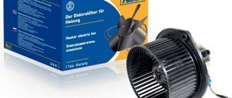
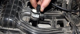
The ignition coil of the VAZ 2107 is located in the engine compartment on the left side of the engine and is secured to the body with two nuts. The ignition coil is an independent element of the vehicle's electrical equipment that converts low voltage current into high voltage current up to 10-20 kV, which should be sufficient to break the gap on the spark plugs and sufficient to ignite the combustible mass. The coil is non-separable, which means that if it fails, it cannot be repaired and must be replaced with a new one.
The ignition coil is a transformer consisting of an internal magnetic circuit, primary and secondary windings, as well as an external magnetic circuit connected to the ignition distributor.
To remove the coil you will need a ten and eight wrench, also disconnect the battery.
- Disconnect the central magnetic circuit from the coil.
- Unscrew the two nuts securing the power wires with a wrench.
- Using a ten-socket wrench, unscrew the two nuts securing the coil to the car body, remove the ground wire and remove the coil from the studs.
At this point, work on removing the ignition coil of the VAZ 2107 is completed. Before replacing it with a new one, you need to make sure that it is not working; for this you will need a multimeter. Before checking, thoroughly clean the primary winding leads on the coil body (two studs to which the power wires are attached) from dirt and oxides.
- First, let's check the resistance of the primary winding. To do this, connect the ohmmeter terminals to the terminals of the primary winding (two pins on the body) and take measurements. Depending on the type of coil being tested, the resistance should be: B-117A = 3-3.5 Ohm; 27.3705 = 0.45-0.5 Ohm.
- Now we check the resistance in the secondary winding circuit. To do this, we connect one ohmmeter probe to the terminal of the high-voltage wire, and leave the second at the terminal of the primary winding. The resistance should be equal: B-117A = 7.4-9.2 kOhm; 27.3705 = 5-0.5 kOhm.
At this point, the repair work on removing and checking the ignition coil of the VAZ 2107 is completed. If, after checking, deviations from the norm are found, it is recommended to replace the coil with a new one.
Sources
- https://semerkavaz.ru/ehlektrooborudovanie/zamena-i-regulirovka-modulya-zazhiganiya-na-vaz-2107/
- https://autodont.ru/system-of-ignition/rabota-s-modulem-zazhiganiya
- https://remont-vaz2106.ru/katushka-zazhiganiya-vaz-2107
Useful tips
- To ensure normal ignition operation, high-quality spark plugs should be installed. This is especially important when the car is running on gas.
- Poor quality wires often cause ignition malfunctions. It is better to use wires with silicone insulation, which has better dielectric characteristics and is more durable.
- Poor fixation of the wire block often causes failure of the switch. To avoid this, it is necessary to check the quality of the connector fit.
- On VAZ models older than 1994, when installing electronic ignition, the tachometer stops working. You can fix the problem by installing a 1.2 kOhm resistor or a capacitor in the circuit between the coil and the tachometer.
The only drawback of electronic ignition on a VAZ is its complete inoperability if the hall sensor breaks down. This is not a very common, but quite possible event. To completely protect yourself from this problem, you should buy a spare sensor and carry it with you.
Troubleshooting
The first sign of loss of vacuum booster seal is not deterioration of the brakes, as many sources on the Internet describe the malfunction. When air just begins to leak through the leaky membrane, the VUT continues to function properly, since the motor manages to maintain a vacuum in the front chamber. The first symptom is changes in the operation of the engine itself:
- due to air leaks into the third cylinder, the engine begins to “trouble” at idle;
- crankshaft revolutions “float”, the stronger the suction, the greater the amplitude of oscillations;
- a running engine reacts to the brake pedal and stalls when pressed sharply;
- Gasoline consumption increases.
Air leaking into the engine through the VUT causes the third cylinder to turn off - the engine begins to “trouble.”
If the car owner ignores the primary symptoms, the situation gets worse - the pedal becomes harder and requires more physical effort to slow down and stop the car. The car can be used further; a breakdown of the VUT does not lead to a complete failure of the brakes, but it significantly complicates driving, especially if you are not used to it. Emergency braking will become a problem.
How to make sure that the vacuum booster is leaking:
- Loosen the clamp and remove the vacuum pipe from the fitting on the manifold.
- Plug the fitting with a tight homemade plug.
- Start the engine. If the revs level out, the problem clearly lies in the amplifier.
- Remove the high voltage wire and remove the spark plug for cylinder III. If the VUT fails, the electrodes will be smoked with black soot.
Whenever possible, I use the old “old-fashioned” method - I simply pinch the vacuum hose with pliers while the engine is running. If the third cylinder starts working and idle speed is restored, I proceed to checking the brake booster.
Similarly, the problem can be temporarily fixed while on the road. Disconnect the pipe, plug the fitting and calmly go to the garage or service station - the power unit will operate smoothly, without excessive fuel consumption. But remember, the brake pedal will become hard and stop responding instantly to light pressure.
Additional diagnostic methods:
- Press the brake 3-4 times and start the engine while holding the pedal. If it does not fail, the valve has probably failed.
- With the engine not running, disconnect the hose from the fitting, remove the check valve and firmly insert a pre-compressed rubber bulb into the hole. On a sealed amplifier it will retain its shape, on a faulty amplifier it will fill with air.
Using a bulb, you can accurately determine the location of the defect, but the vacuum booster will have to be removed. While pumping air into the chamber, wash the edges of the joints and the stem seal - bubbles will indicate the location of damage.
Porhen2107 › Blog › No spark from the ignition coil - possible reasons:
A situation in which the engine does not start the first time, or does not start at all, can hardly be called pleasant. Experienced motorists know that any malfunction of the ignition system leads to partial and often even complete failure of the car engine.
So, if your car does not start the reasons:
• no current signals are supplied to the ignition coil; • fuel does not reach the carburetor; • current from the ignition coil does not enter the distributor; • reason there is no spark from the ignition coil; • no spark passes between the electrodes of the spark plug; • fuel liquid does not enter the combustion chamber; • the ignition distributor is broken.
The engine may also be blocked by the starter. But before checking the starter, inspect the condition of the electric motor winding; if it is not damaged, then the starter is most likely in good condition. Pay attention to the ignition coil.
The ignition coil is the converter of low voltage current to high voltage current in a vehicle's ignition system.
Malfunctions of the ignition coil are expressed by the following actions of the car:
• reduction in engine operating intensity; • problems starting the engine; • a sharp decrease in the minimum engine speed, and interruption of its operation when the vehicle is idling; • increase in fuel costs.
How to check the ignition coil.
Inspect this mechanism for oil stains and cracks. If the surface of the coil is not perfectly clean, wipe off the dirt with a dry cloth, otherwise it may cause high voltage leakage. Also pay attention to the ignition system wires; they must be dry and without external damage. Move the high-voltage wires with your hand and try to start the car. If this does not work, then you will have to check the ignition system more carefully.
To diagnose the condition of the spark plugs, take two high-voltage wires, having first removed them from the distributor cap. Place the wires at a distance of 5-7 mm from the car engine and wait for the reaction. If the system is fully operational, then when the starter is cranked, a blue spark will appear in this gap. If there is no spark or a color other than blue, check the ignition coil.
The coil is checked in the same way. Remove the wire that goes from the coil to the distributor-breaker (distributor), and, by analogy with checking the spark plugs, with the starter running, bring the wire to the ground of the car. If there is no spark from the coil, then it is faulty.
Connect the ignition coil to an ohmmeter to check for breaks in the wires. Check the primary and secondary windings. The absence of holes will be confirmed by the ohmmeter readings: 3 Ohms and 7000 Ohms in the primary and secondary windings, respectively. If the resistance is less than standard values, then you are most likely in danger of replacing the ignition coil. Check the correct connection of the coil wires and its insulation. If the wires are tangled together, correct this by untangling them and positioning them correctly. Use an ammeter to check the current in the circuit. To do this, connect the contacts of the distributor and turn on the ignition. The current strength displayed by the device should not be higher than that set for your car. If the current value is greater than the standard value, it means that there is a break in the coil winding caused by a short circuit.
A malfunction in the operation of the ignition coil most often occurs when the ignition system is turned on when the engine is turned off. As a result, the insulation of high-voltage wires overheats, cracks, and crumbles over time, thus causing a short circuit.
If a faulty ignition coil is detected, it can be repaired or replaced with a new one. Repairing the ignition coil consists of separating the mechanism into parts; checking for cracks, chips, scratches; cleaning up damage; restoring the ideal surface of the shell by gluing them with a special compound. Replacing the ignition coil with a new coil with exactly the same characteristics is possible. Connect the ignition coil with the utmost care, take special care to ensure the correct connection of the wires. Otherwise, the contacts may overheat and short circuit.
The appearance of a spark, correct readings of the ohmmeter and ammeter, indicate the serviceability of the unit being tested, and the breakdown of another component of the ignition system. The lack of a spark in the car system can also cause the following problem: the car does not start - the starter turns, there are cases when replacing the ignition switch helps.
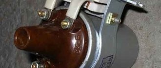
Ignition coil design
Almost all ignition coils on VAZ cars are conventional step-up transformers equipped with two windings - primary and secondary. Between them is a massive steel core. All this is placed in a metal case with insulation. The primary winding is made of copper wire coated with varnish insulation. The number of turns in it can vary from 130 to 150. It is this winding that is supplied with an initial voltage of 12 volts.
The design of the ignition coil on the VAZ 2107 cannot be called complex
The secondary winding is located on top of the primary. The number of turns in it can reach 25 thousand. The wire in the secondary winding is also copper, but its diameter is only 0.2 mm. The output voltage supplied to the spark plugs from the secondary winding reaches 35 thousand volts.
Types of ignition coils
Over the years, different types of ignition coils were installed on VAZ cars, which differed in design:
- common coil. One of the earliest devices that was installed on the very first G7s. Despite its venerable age, the coil is still installed on the VAZ 2107 today. The design of the device was described above: two copper windings on top of a steel core;
- individual reel. It is mainly installed on cars with electronic ignition systems. In these devices, the primary winding is also located inside the secondary, but individual coils are installed on all 4 VAZ 2107 spark plugs;
- twin coils. These devices are only used on vehicles with electronic ignition systems. These coils differ from all others in the presence of double wires, thanks to which the spark is supplied not to one, but to two combustion chambers at once.
Location and connection diagram
The ignition coil on VAZ 2107 cars is located under the hood, near the left mudguard. Attached with two long studs. A rubber cap with a high-voltage wire is connected to it.
The ignition coil on the VAZ 2107 is located under the hood on the left, near the mudguard
The coil is connected according to the diagram below.
The connection diagram for the VAZ 2107 ignition coil is not particularly complicated
About the choice of ignition coils for the VAZ 2107
The latest VAZ 2107 cars are equipped with contact ignition systems that use a domestically produced B117A coil. The device is quite reliable, but every part has its own service life. And when the B117A fails, it is quite difficult to find it on sale.
Standard coil VAZ 2107 - B117A
For this reason, motorists prefer to install a 27.3705 coil. It costs more (from 600 rubles). Such a high price is explained by the fact that the 27.3705 coil is filled with oil inside, and the magnetic circuit in it is of the open type. It is this device that is recommended to be used when replacing a burnt out coil.
Coil 27.3705 - oil-filled, with an open core
The third option should also be noted here: coil 3122.3705. There is no oil in this coil, and the magnetic circuit is closed. Despite this, it costs more than 27.3705 (from 700 rubles). Coil 3122.3705 is as reliable as 27.3705, but given its inflated price, most car owners opt for 27.3705. Foreign-made coils are not installed on the VAZ 2107.
Reel design and operation
The modern bobbin is a simplified version of the Ruhmkorff induction coil. It was named after the German-born inventor Heinrich Ruhmkorff, who was the first to patent a device in 1851 that converts low-voltage direct voltage into high-alternating voltage.
To understand the principle of operation, you need to know the structure of the ignition coil and the basics of radio electronics.
This is a traditional, common VAZ ignition coil, used for a long time and on many other cars. In fact, this is a pulse high-voltage transformer. On a core designed to enhance the magnetic field, a secondary winding is wound with a thin wire; it can contain up to thirty thousand turns of wire.
On top of the secondary winding is a primary winding made of thicker wire and with fewer turns (100-300).
The windings at one end are connected to each other, the second end of the primary is connected to the battery, the secondary winding with its free end is connected to the voltage distributor. The common point of the coil winding is connected to the voltage switch. This entire structure is covered by a protective housing.
A direct current flows through the “primary” in the initial state. When a spark needs to be formed, the circuit is broken by a switch or distributor. This leads to the formation of high voltage in the secondary winding. Voltage is supplied to the spark plug of the desired cylinder, where a spark is formed, causing combustion of the fuel mixture. High-voltage wires were used to connect the spark plugs to the distributor.
The single terminal design is not the only one possible; there are other options.
- Double spark. The dual system is used for cylinders that operate in the same phase. Let's assume that compression occurs in the first cylinder and a spark is needed for ignition, and in the fourth cylinder there is a purge phase and an idle spark is formed there.
- Three-spark. The principle of operation is the same as that of a two-terminal one, only similar ones are used on 6-cylinder engines.
- Individual. Each spark plug is equipped with its own ignition coil. In this case, the windings are swapped - the primary is located under the secondary.
How to check the ignition coil (bobbin) on a car
For a gasoline internal combustion engine, the ignition system is one of the determining ones, although it is difficult to single out any main component in the car. You can’t go without a motor, but it’s also impossible without a wheel.
The ignition coil creates high voltage, without which it is impossible to form a spark and ignite the fuel-air mixture in the cylinders of a gasoline engine.
Design and principle of operation of the BZ
Contactless or electronic ignition on the VAZ 2107 is installed on models with injection engines. Carburetor sevens were supplied from the factory with contact ignition systems, which have many disadvantages. If you plan to install a contactless ignition module, then before starting it won’t hurt to understand the issue of its design.
The ignition system is the mechanism by which a pulsed voltage is created to supply the spark plugs in order to promptly ignite the fuel-air mixture in the cylinders. The main disadvantage of contact SZ is that the contact groups require regular cleaning, replacement and adjustment. As soon as difficulties arose with igniting the combustible mixture, the car owner immediately knew where to look for the reasons.
With the advent of the BSZ, these difficulties automatically disappeared. To understand why, let’s look at the components of the mechanism:
- Electronic type switch with transistors.
- Double winding coil.
- A distributor or distributor equipped with a Hall sensor, a slider and a contact cover.
- Spark plugs with armored wires.
The BSZ diagram for the VAZ 2107 is shown in the photo below.
Based on this diagram, let's consider the principle of its operation:
- When you turn the ignition key, current is supplied to the primary winding of the coil, thereby creating a magnetic field.
- When the engine starts, power is supplied to the starter coil and the rotor begins to turn the crankshaft.
- In this case, the crankshaft rotates the distributor shaft, which is connected to the runner.
- As soon as the shaft with the slider rotates, this phenomenon is detected by the Hall sensor (along the protrusion on the shaft) and transmits the corresponding signal to the switch.
- When a signal arrives at the switch, the primary winding of the coil is de-energized (on the low-voltage side).
- A powerful discharge of about 25-30 kV is induced in the secondary (high-voltage) winding, transmitted to a moving contact located at the end of the distributor shaft.
- When the slider moves in a circle, it practically touches the contacts in the cover, a spark occurs between them, and a high voltage discharge is transmitted to each of the contacts in turn.
- This discharge flows through armored cables to the spark plug electrodes.
The mechanism in question received the name “contactless” due to the connection and disconnection of the circuit of the primary winding of the coil with a commutator due to the output transistor (without using contacts).