VAZ 2107 is a popular domestic car, which is widespread in the CIS countries. Over its long production period, the “seven” remained virtually unchanged except for the engine. Starting from the 00s, the VAZ 2107 began to be equipped with an engine with fuel injection.
All engines in which fuel injection is carried out through an injector have a large number of different sensors. Sensors are necessary for the correct and reliable operation of the internal combustion engine.
This article will talk about the coolant temperature sensor on a VAZ 2107 car, namely its location, purpose, signs of malfunction and how to replace it yourself.
DTOZH sensor
The VAZ 2107 uses two temperature sensors: one is responsible for working with the computer and measuring the temperature, and the second is for turning on the fan when a certain temperature is reached.
Purpose
The temperature sensor is designed to determine the temperature of the coolant and transmit the readings to the electronic engine control unit (ECU). Its tasks include not only determining the temperature, but also adjusting the fuel mixture, namely, based on the readings from the DTOZH, the engine block determines the required amount of fuel and forms the fuel mixture.
During warm-up in the cold season, you may notice increased warm-up speed.
Design
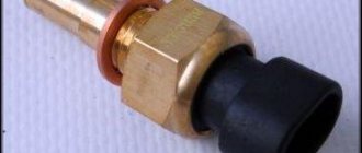
The design of the sensor is quite simple; a thermistor is placed in its body, which changes its resistance with changes in temperature. The sensor is most often made of bronze and plastic. Has a connector with an output for connecting the power supply.
Checking for serviceability
Before checking the operating capabilities, it is worth paying attention to the fuses. Often their burnout causes sensor failure.
You can independently check the sensor for correct operation using certain tools: a household multimeter, a boiler, a thermometer. A container of water will also come in handy.
- The entire threaded area of the sensor is placed in water.
- Together with the DTOZH, a thermometer is lowered into the container.
- The contacts of the multimeter and the sensor are connected, the resistance is measured.
- The boiler is immersed remotely from other devices and connected to the network, the liquid is heated.
- Indicative temperature – 95 °C. There should be no resistance with it. When the multimeter confirms this, it means that the spare part is functioning correctly. If resistance is observed, the device is broken.
Restoring the temperature sensor is not possible. There are no individual parts or materials available for sale that could be used to repair the device. The main reason is the cast housing design. The impossibility of disassembly does not provide access to the internals and, especially, to replace them.
Where is
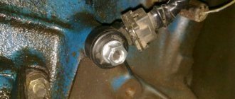
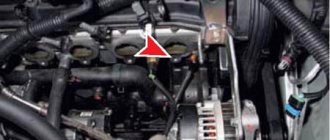
The sensor is located on the cylinder head between the third and fourth cylinders. It got this location for a reason: these cylinders are the most heat-loaded and therefore the sensor is installed there to monitor the temperature in the hottest section of the engine.
The fan switching temperature sensor is located in the cooling radiator; the radiator has a special threaded hole into which the sensor itself is screwed.
Forced fan activation
If the VAZ 2107 fan sensor is broken, it is quite possible to drive on a good road without noticing it. But as soon as you drive onto a country road or get into city traffic jams, the engine will start to overheat. Replacing the fan sensor is not very difficult, but requires draining the coolant. Even if you have a spare sensor at hand, replacing it on the road is problematic. There is an easier way out of the situation.
The following operations must be performed:
- disconnect “mass”;
- remove two wires from the sensor terminals and connect (“short-circuit”) them;
- insulate the exposed contacts of the connected wires;
- connect ground.
In this case, the fan will run continuously. To turn it off, you will have to disconnect the ground and disconnect the contacts.
If you have already experienced problems with the fan sensor on the road, you can install a forced fan circuit on the car that operates in parallel with the sensor. To do this, just connect a couple of wires to the terminals going to the sensor contacts and stretch them into the engine compartment. Install a separate button (toggle switch) on the dashboard and connect the wires to it so that you can close them if necessary.
In this case, if the sensor malfunctions, there will be no need to crawl under the hood to force the fan to start.
Symptoms of a problem
There are not very many breakdowns of the sensor, but its malfunctions can be confused with other car malfunctions. Therefore, computer diagnostics will help identify the real culprit of engine malfunction, but you can suspect the DTOZh of a breakdown using its signs of breakdown.
DTOZH malfunctions:
- The car does not start well;
- There are no increased speeds when warming up;
- Increased fuel consumption;
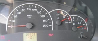
- The coolant temperature scale does not show;
Malfunctions of the fan switch sensor:
- The fan does not turn on automatically;
- Low or high fan temperature;
Why does the sensor fail?
There may be several reasons for the breakdown:
- Sensor insulation failure. If the wiring is poorly insulated, a short circuit occurs, which causes the device to burn out.
- The wires break near the sensor, which prevents the fan from turning on and the car overheats.
- The electrical contact located inside breaks or becomes cracked. In this case, accurate data transfer to the control panel is not possible.
Failure occurs more often in winter.
Replacement
Replacing these sensors is a fairly simple job that almost anyone can handle. Replacement can be carried out in two ways, with and without draining the coolant.
The second replacement option is faster and is used most often, so we will consider the option of replacing the DTOZH without draining the coolant.
Attention! Replacement should be carried out on a cold engine to avoid burns.
Replacement process
- Remove the connector from the sensor that will be replaced;
- Use a key to unscrew the sensor counterclockwise and plug the sensor hole with your finger;
- We take a new sensor and quickly install it in place;
Coolant losses with such a replacement are minimal, and the time saved is about an hour.
After replacement, you need to check the antifreeze level and add it if necessary.
Replacing the coolant temperature sensor on a VAZ 2107
Replacing the coolant temperature sensor on a VAZ 2107 is carried out according to the instructions presented below.
- Disconnect the on-board network.
- Drain the coolant from the cylinder block.
- Slide the protective cap on the sensor and disconnect the wire.
- Using a 21 wrench or a deep socket, unscrew the sensor.
- Install the new sensor in reverse order.
For carburetor systems
There are still many VAZ 2107 cars in use on the roads with a carburetor supply of the fuel mixture. As in the injector, engine cooling occurs thanks to the radiator and fan, only the process is regulated by a fan sensor.
Location and principle of operation
On older cars, additional cooling begins when the antifreeze reaches a certain temperature, usually 92 °C (there are differences for individual sensors). Carburetor systems are equipped with 2 coolant sensors - one to regulate fan operation, and the second sends readings to the driver’s instrument panel.
The sensor that turns on the fan is located on the bottom of the radiator panel, on the right side. To see it, you need to lift the hood and on the back you can see a “nut” with wiring. Usually these are modifications of the TM-108.
The principle of operation is to change the volume of the working fluid of the sensor when the temperature of its working fluid fluctuates. Inside the thick-walled steel housing is a working mixture covered with a flexible plate attached to a pusher that connects the contacts when the sensor is triggered.
In the steel case, the sensor heats up evenly, the working fluid expands and the contacts are connected, the fan is activated.
There are several modifications of the devices - TM108; TM108-10; 661.3710. The first is designed for operating temperatures: 92–99 °C (contact activation and disconnection). The second is designed for colder operating conditions: 87–92 °C. These sensors operate in a circuit with an additional relay and can withstand a current of 1 A. If a relay contact is not provided and the fan is connected directly to the sensor, then the latest 16 A model is used.
Electrical diagram of the VAZ 21074 car
A high-quality color diagram of the electrical equipment of the domestic passenger car VAZ-21074 is provided to help auto electricians and service stations. Model 21074 is an improved modification of the VAZ-2107. The “seventy-four” is equipped with the same 1.6-liter engine, but the carburetor is replaced with an injector. Some elements of the circuit are installed not on all, but only on part of the produced cars of this model. At the end of the article, fuses and the circuits they protect are shown. Schemes are enlarged by clicking.
Electrical equipment VAZ-21074
- 1- block headlights;
- 2- side direction indicators;
- 3- rechargeable battery;
- 4- starter activation relay;
- 5- carburetor electro-pneumatic valve;
- 6- carburetor microswitch;
- 7- generator 37.3701;
- 8- gearmotors for headlight cleaners*;
- 9- fan motor activation sensor;
- 10- electric motor of the engine cooling system fan;
- 11- sound signals;
- 12- ignition distributor;
- 13- spark plugs;
- 14- starter VAZ-21074;
- 15- coolant temperature indicator sensor;
- 16- engine compartment lighting lamp;
- 17- low oil pressure indicator sensor;
- 18- low brake fluid level indicator sensor;
- 19- windshield wiper gearmotor;
- 20- carburetor electro-pneumatic valve control unit;
- 21- ignition coil;
- 22- electric motor of the headlight washer pump*;
- 23- electric motor of the windshield washer pump;
- 24- mounting block;
- 25- windshield wiper relay;
- 26- hazard warning and direction indicator relays;
- 27- brake light switch;
- 28- reversing light switch;
- 29- ignition relay;
- 30- ignition switch;
- 31- three-lever switch;
- 32- alarm switch;
- 33-plug socket for a portable lamp**;
- 34- heater fan switch;
- 35 - additional resistor of the heater electric motor;
- 36 - indicator lamp for turning on the heated rear window;
- 37 - indicator lamp for insufficient brake fluid level;
- 38 - signaling unit;
- 39- heater fan electric motor;
- 40 - glove box lighting lamp;
- 41 - lamp switch on the front door pillars;
- 42- switch for alarm lights of open front doors***;
- 43- alarm lights for open front doors***;
- 44- connecting block;
- 45- cigarette lighter;
- 46- watch VAZ-21074;
- 47- switch for instrument lighting lamps;
- 48- diode for checking the serviceability of the warning lamp for insufficient brake fluid level;
- 49 - fuel level indicator;
- 50 - fuel reserve indicator lamp;
- 51- speedometer;
- 52 - turn signal indicator lamp;
- 53- indicator lamp for closing the carburetor air damper;
- 54 - battery charging indicator lamp;
- 55- carburetor air damper closed warning switch;
- 56 - instrument cluster;
- 57- econometrician;
- 58- courtesy light switches on the rear door pillars;
- 59 - coolant temperature indicator;
- 60 - tachometer 21074;
- 61- parking brake indicator lamp;
- 62 - low oil pressure indicator lamp;
- 63- high beam indicator lamp;
- 64- indicator lamp for turning on external lighting;
- 65-voltmeter;
- 66- parking brake indicator switch;
- 67- switch for external lighting lamps;
- 68- rear window heating element switch with backlight;
- 69- switch for rear fog lights with on/off indicator*;
- 70 - fog light circuit fuse;
- 71- lampshade;
- 72 - rear lights VAZ 21074;
- 73 - level indicator and fuel reserve sensor;
- 74- pads for connecting to the rear window heating element*;
- 75 - license plate lights.
VAZ 21074 engine control system diagram
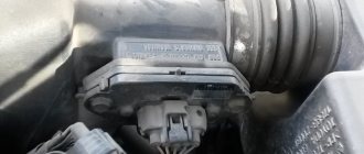
Wiring diagram of electrical connections of ECM VAZ 21074 - circuit elements. 1 — controller connector; 2 — mass air flow sensor; 3 — coolant temperature sensor; 4 — crankshaft position sensor; 5 — throttle position sensor; 6 — oxygen concentration sensor; 7 — speed sensor; 8 — ignition module; 9 — solenoid valve for purge of the adsorber; 10 — electric fan relay; 11 — electric fuel pump relay; 12 - main relay; 13 - fuse for the power circuit of the electric fuel pump relay: 14 - fuse for the power circuit of the main relay; 15 — fuse-link; 16-fuse protecting the constant power supply circuit of the controller; 17 - diode; 18 — idle speed regulator; 19 — nozzles; X1 - diagnostic block; X2 - connection block to the vehicle electrical system.
Fuse box VAZ-21074 injector
- 1-Rear window heating relay
- 2-Relay for headlight cleaners and washers (if equipped)
- 3-relay or signal jumper (if there is no external relay)
- 4-relay or jumper for cooling fan
- 5-high beam relay
- 6-low beam relay
- F1-F17-Fuses
- 1 (8A) Rear lights (reversing light). Heater electric motor. Warning lamp and rear window heating relay.
- 2 (8A) Electric motors for windshield wiper and washer. Electric motors for headlight cleaners and washers. Windshield wiper relay. Wiper relay and
- headlight washer (contacts).
- 3 (8A) Reserve.
- 4 (8A) Reserve.
- 5 (16A) Rear window heating element and heating relay (contacts)
- 6 (8A) Cigarette lighter. Portable lamp socket. Watch. Front door open warning lamps
- 7 (16A) Sound signals and relay for turning on sound signals. Engine cooling fan electric motor and motor activation relay.
- 8 (8A) Direction indicators in hazard warning mode. Switch and relay-interrupter for direction indicators and hazard warning lights in emergency mode.
- 9 (8A) Generator voltage regulator.
- 10 (8A) Direction indicators in turn indication mode and the corresponding warning lamp. Fan motor activation relay (winding). Control devices. Battery charge indicator lamp. Indicator lamps for fuel reserve, oil pressure, parking brake and brake fluid level. Parking brake warning light relay. Carburetor pneumatic valve control system
- 11 (8A) Rear lights (brake lamps). Body interior lighting lamp.
- 12 (8A) Right headlight. Coil of the relay for turning on the headlight cleaners (with the high beams on)
- 13 (8A) Left headlight. Indicator lamp for turning on the high beam headlights.
- 14 (8A) Left headlight (side light). Right rear light (side light). License plate lights. Engine compartment lamp. Indicator lamp for turning on the side light.
- 15 (8A) Right headlight (side light). Left rear light (side light). Cigarette lighter lamp. Instrument lighting lamps. Glove compartment lamp
- 16 (8A) Right headlight (low beam). Coil of the relay for turning on the headlight cleaners.
- 17 (8A) Left headlight (low beam).
Instrument location
The coolant temperature sensor (CTS) is embedded in the cooling radiator. It is this position, in which there is direct contact with the heating antifreeze, that ensures high sensitivity of the part.
In outdated models, the meter acted as a plug to close the tank. In the new ones, the drain passage is sealed with a separate plug, and the temperature sensor has its own hole.
The device is located directly on the engine block head. To find it, you should look at the power unit on the left, or follow the outgoing wire from the instrument panel to which the meter is connected. After the car owner has found the device, further operations can begin.
DIY replacement instructions
To replace the sensor, do the following:
- First, open the hood and disconnect the battery.
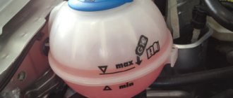
- Remove the coolant expansion tank cap and unscrew the cap from the radiator unit. This will prevent the formation of high pressure in the system.
- Next, place a container under the radiator assembly - the antifreeze will pour into it after removal. Turn off the tap and wait until the liquid drains.
- When these steps are completed, you will need to disconnect the wiring connector from the device. Next, using a 30mm wrench, you will need to unscrew the sensor and remove it from its seat. When dismantling, do not lose the steel seal, and before further installation it will be necessary to treat the installation site with sealant. It is important that the sealant itself is high-temperature - treating the seat with it will prevent leakage of consumables.
- When the device is installed, it is necessary to reinstall the plug on the radiator assembly. Further assembly is carried out in the reverse order - first you need to fill in the coolant, then connect the battery terminal.
- To diagnose the performance of the device, you need to start the power unit and warm it up to operating temperature so that the fan turns on.