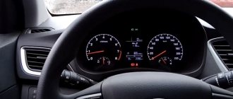
The French car is in demand among domestic motorists due to its moderate cost and high reliability of components. The Renault Duster dashboard is a module that displays complete information about the state of the vehicle’s on-board systems in real time. The equipment of the car is extremely unified. On models that consume gasoline or diesel, the location and purpose of the indicators is minimal. Also, the symbols of the 2012 modification do not differ from the versions after the 2022 restyling. The board is divided into two compartments with a liquid crystal display and an indicator board.
The instrumentation is made in a modern form factor, where only the speedometer and odometer remain arrow-shaped. The remaining elements of the panel are completely electronic.
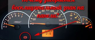
The “cardiogram” on the Renault Duster caught fire: reasons
The saw icon on Duster cars often warns of electronic failure.
The sensor also informs about problems in the operation of the engine ECU, injection sensors, mass air flow, lambda probe or malfunctions of the fuel supply sensor. The saw may appear if the speed sensor on the automatic transmission is faulty.
Also, if the saw caught fire on your Duster, you should check the throttle body, valve and exhaust gas recirculation (EGR) catalyst. All these units are contaminated with soot and soot deposits, which leads to unstable operation of the mechanisms and causes errors in the operation of the internal combustion engine during the formation of the fuel mixture.
The indicator also signals depressurization of the intake system, contamination of the air filter and failure of the turbine, which leads to interruptions in the air supply to the engine.
When starting a cold engine, the saw sometimes lights up if faults in the ignition coils of gasoline engines prevent the normal ignition of the fuel mixture. Also, when the ignition is turned on, the “cold” indicator may indicate a failure of the electronic circuit of the glow plug relay in diesel engines.
Other problems that cause the light saw to turn on include:
- The appearance of water in diesel fuel.
- The need to replace the fuel injector on a diesel engine (fault code - P1241);
- Throttle valve contamination (error code in throttle valve drive circuit - DF078);
- Malfunction of the relay responsible for the rotation speed of the cooling fan motor (error DF019);
- Insufficient air in the engine (when the indicator lights up after acceleration, starting from third or fourth gear, and also when the engine is subjected to significant load, for example, on an incline). The problem is indicated by error DF301.
Crossover engines
SUV engines are simple and reliable. The basic naturally aspirated 1.6 H4M-HR16DE is common in our country and does not particularly stand out from its competitors. Capable of traveling up to 250,000 km. It is unpretentious to gasoline and runs easily on 92-octane gasoline. The engine has a timing chain of a reliable design. Such a belt does not require replacement up to 200 - 250 thousand km.
Engine 2.0 F4R-143 hp-195 NM – a real long-liver. Since the first release in 1993, it has not undergone any significant changes. Of course, the manufacturer has been trying to maintain the naturally aspirated engine in good condition over the years through various upgrades. After the 2015 update, the engine became more powerful by 8 horsepower.
Problems with the 2.0 engine with a capacity of 143 hp. With.
1.5 dci-K9K-109 hp-200/240 Nm – diesel unit. The engine is very economical, but demanding on fuel quality. Due to poor-quality diesel fuel, problems arise with the injectors and the crankshaft liners rotate. The engine life depends on the frequency of oil changes. According to reviews from diesel Duster owners, it is known that if the engine is serviced twice as often as the manufacturer recommends, the mileage before overhaul will be 300 - 400 thousand kilometers.
Repair: rotation of the liner
Until 2022, the Renault Duster was equipped with an aspirated 1.6 K4M-102 hp-145 NM. In terms of technical characteristics, the engine was distinguished by its simplicity of design, cheap spare parts and good maintainability, but long acceleration - 13 s. Installed with a manual transmission. Now cars with this engine are sold on the secondary market.
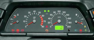
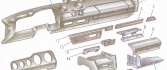
Icons on the Renault Duster dashboard and what they mean
Near the signs there are signal signs with narrow designations. The pictures warn the driver about possible breakdowns, critical malfunctions in the operation of the units and on-board vehicle.
The sorted icons explain what they mean:
- 6 - one of the doors is not closed;
- 9 — the engine is overheated and needs to be stopped to cool down;
- 10 - a malfunction has been detected in the on-board electronics and requires repair;
- 13 - the ECM system is faulty or does not work correctly;
- 15 - indicator of correct battery charge, turns on when the voltage drops critically;
- 16 - an unacceptable oil pressure drop is observed in the engine crankcase;
- 17 - lights up when the fuel runs out, when there is less than 8 liters of fuel left in the tank;
- 22 — the operation of the airbags is stopped;
- 24 - The ABS module is damaged or does not work correctly.
The icons in the order are valid for 2015-2016 models. The symbols described may differ in other versions.
Decoding the Renault Duster 2 instrument display
The standard instrument panel of Duster 2 is a single instrument panel for all basic, in addition to top-end assemblies with the presence of warning and warning graphic indicators, the explanation of which is given in the table below:
| Graphic and color display of indication | Alert form | What does it mean? |
| Constantly signaling red or yellow triangle with an exclamation mark. | The presence of an abnormal dangerous situation such as a sudden stop in oil supply, an open door, or a short circuit in the electrical wiring. | |
| A permanent red exclamation point or P in a circle, red BRAKE. | Clamped handbrake, deficiency of brake fluid, extreme wear of brake consumables (linings, discs). | |
| Red/blue thermometer. | The maximum or minimum temperature of antifreeze or any other coolant. | |
| Constant signal of a red or yellow watering can, the inscription Oil Level or the additions Min, Sensor to the yellow image of the watering can | A drop in lubricant pressure in the engine circuit, the oil level in the crankcase is below the minimum value, an urgent need to top up engine oil. | |
| Constant signal in the form of a red silhouette of the battery | Problems with charging the battery, faulty wiring, relay or generator. | |
| Red silhouette of a car with open doors. | The front or rear doors are not closed or not tightly closed. | |
| Constant red light for passenger with seat belt | Unfastened or problems with seat belt | |
| A constant red signal of the profile of a seated person with a ball on his knees, as well as the red inscriptions AIR BAG, as well as SRS. | Problems with airbags providing passengers with passive safety elements. | |
| A permanent red or yellow exclamation mark in the gears of the corresponding color | Problems with the box or transmission components | |
| Red steering wheel with an exclamation icon next to it. | Problems with power steering, tight steering, difficulty turning the steering wheel. | |
| Constant yellow AT signal | Failures in the automatic transmission electrical unit | |
| Yellow lightning signal in a circle | Parking brake problems | |
| Yellow circle with dotted lines | Evidence of dangerous brake pad wear | |
| Yellow exclamation mark in tire profile | High tire pressure | |
| Yellow circle with boot | Reminder to unlock the box by pressing the brake pedal | |
| Silhouettes of engines in yellow, sometimes with the inscription CHECK or simply the inscription CHECK ENGINE | Evidence of errors in engine systems or problems with the ECU stuffing with the possibility of completely disabling some automotive systems until the problem is eliminated or until errors are reset after flashing the software. | |
| Yellow slider with downward arrow | A sharp drop in power or an erroneous signal that disappears after rebooting the computer | |
| Inscription OIL CHANGE | Indicates the need for an urgent replacement of engine lubricant. | |
| Yellow signal 4WD | There are problems in the all-wheel drive system. | |
| Signal in the form of a yellow inscription DAS ASR | Problems may occur during emergency braking. | |
| CVT inscription | Indicates the normal operation of the variator on Renault Duster 2 with the presence of appropriate transmissions. | |
| Blue headlight signal | Indicates normal operation of high beam optics | |
| Green DRL lettering | Indicates that the daytime light switching system is working properly | |
| Green headlights oriented in different directions | Normal functioning of the light alarm. | |
| Icon of a green car located on a slope or on a mountain. | Evidence that the descent or ascent assist is turned on. | |
| Green indication ECO icon with the inscription ECO MODE. | Is activated, or Duster 2 moves in accordance with the fuel saving mode. |
It is quite obvious that not all Renault Duster 2 display icons are presented here; these are just examples of how the standard instrument panel of the French crossover notifies and warns the driver about the current state of the vehicle’s systems and components.
Symbols on the dashboard
On modern cars, the operating characteristics of control devices often change; they are equipped with new functions and systems, with their own indicators that have their own new symbols. Graphic designations of indicator lights for the same systems on cars of different brands may look different, even with the same arrangement of sensors and instruments on their panels.
Therefore, sometimes it is difficult to immediately understand the meaning of icons, pictograms and symbols on the Renault Duster instrument panel, indicating the functionality of certain indicators. However, every driver must be fully aware of all symbols on their vehicle's dashboard. This will, among other things, allow you to promptly learn about a critical situation or prevent breakdowns and even accidents.
Explanation and description of icons and symbols on the Duster toolbar:
- tachometer, shows the number of revolutions of the crankshaft, has a red zone on the scale - an unacceptably high speed value;
- the remaining fuel indicator may give erroneous readings on rough roads;
- button for setting the time and switching the odometer (calculating daily mileage);
- speedometer, shows the current speed and the number of kilometers traveled;
- the front fog lamp indicator is on;
- open door lamp (any;
- rear fog light indicator;
- here you can install sensors: critical coolant temperature, high beam, low fuel remaining, etc.;
- engine overheating control;
- checking the malfunction of the car electronics, if it turns on while driving - urgently contact a service station for diagnostics;
- warning light for turning on the handbrake and low TJ level, when the warning light is on, any movement is prohibited;
- direction indicator control;
- check the functionality of the engine control; if it is turned on while driving, immediately contact a service station for diagnostics;
- checking the engine lock; when you try to turn on the ignition with a non-standard key, the light flashes and starting the engine becomes impossible;
- checking the battery charge; if it lights up constantly, the charging system is faulty; if the charging current is low, the battery is discharged (after about 10 km); if the charging current is high, the vehicle’s electronics may be damaged;
- checking the oil pressure, if the light is on while the engine is running, there is no oil pressure in the engine, you must urgently contact a service station for diagnostics;
- a warning lamp indicating that the fuel is running out; when it lights up, it is necessary to urgently refuel;
- rear window heating indicator;
- high beam headlight indication;
- 2WD motion indicator light;
- 4WD motion indicator light;
- When monitoring the serviceability of the airbag system, a constant light indicates a malfunction in this system;
- low beam control;
- By monitoring the serviceability of the ABS system, if there is constant combustion, you can very carefully go to the service station yourself to fix the problem.
When you turn the key in the ignition switch, the system is diagnosed and the lights of all Duster sensors are illuminated. Then after a few seconds some go out, while others stop burning only after the engine starts. At the same time, the initial absence of light from the light bulb indicates a malfunction of the lamp itself or the system it controls. You can only figure out what's not working at a gas station using a scanner. All indicators and instruments on the Duster panel (except for the door open indicator) will only work when the ignition is on.
If, while driving, warning lights come on indicating a malfunction of the charging system, a drop in oil pressure in the lubrication system, a critical coolant temperature, a decrease in the TJ level and a malfunction of the brake system, you must stop. After this, turn off the engine and take the Duster to a gas station.
Light bulbs
Manual on front panel indicators. Part one
Manual on front panel indicators. Part two
Manual on front panel indicators. Part three
Manual on front panel indicators. Part four
Manual on front panel indicators. Part five
Color designations of indicator lamps
The indicator lamps on the Renault Duster instrument panel differ not only in the configuration of the pictograms, but also in color combinations, each of which has its own group of signals.
Description of indicators of different colors:
- The glowing red indicators indicate serious malfunctions or important reminders that may jeopardize the safety of the Duster. In this case, you need to stop the car, turn off the engine and take it to a service station. The lamp will remain on until the fault is corrected;
- yellow and orange indicators remind you of the need for maintenance or repair of a particular part. Sometimes this icon flashes. In this case, immediately, taking precautions, you must contact a service station to diagnose and eliminate the reasons for the appearance of these reminders. Otherwise, the car may be damaged;
- The blue and green colors of the lights indicate that a particular function of the machine is working normally.
Installation and installation
The procedure for dismantling and installing the Renault Duster dashboard is simple. This operation is determined, for example, by the failure of instruments and the need to replace the indicator panel or when removing the steering column, in some cases when soundproofing the interior. Before starting work, it is necessary to de-energize the power supply system by removing the “—” (minus) terminal from the battery.
First of all, the decorative casing located in the center of the torpedo is removed. It is attached to eight mechanical fasteners, two located on each side. No fasteners are used here; the clamps are removed with an ordinary, wide, flat screwdriver, which is better to be wrapped in cloth to avoid damage.
Next, using the same screwdriver and overcoming the resistance of the seven fasteners, we remove the decorative panel located to the right of the instruments, next to the one removed. Then, using a screwdriver, we pull out the left plastic cover of the instrument panel from the five clips.
Then, using a screwdriver, we remove the top cover of the visor.
After that, by pulling with your hand, remove the 2 (left-right) upper plastic covers of the instrument panel. Using a Torx T-20 wrench, unscrew 4 screws and pull the panel out of the dashboard. By pressing the latches, we disconnect the “male” and “female” electrical blocks of gray and black colors and completely remove the instrument panel.
The Renault Duster panel cannot be repaired and is simply replaced with a new one. The new part must be installed in the reverse order of removal.
Duster dashboard malfunctions and how to fix them
It is a modern design element made using digital components. The technology eliminates the presence of standard mechanics and moving parts, with the exception of comparators: tachometer and speedometer. As a result, failures of modifications ordered after the release of 2013 can only affect the electrical part.
The most common defects are found.
- Burnout or short circuit of one or more indicators. In this case, repairs are limited to replacing the corresponding lamp or diode with a known working element.
- Damage group contact. Usually caused by voltage surges in the on-board circuit or damage to electrical equipment. Fixed by re-soldering the terminals.
- Burnout pattern. The problem is eliminated by completely replacing the remote control: fixing the problem using other methods is not economically feasible.
Self-diagnosis method when malfunctions occur
To carry out automatic diagnostics of control units, you must:
- Place the key in the ignition lock cylinder, and then press and hold the daily mileage reset button located on the dashboard.
- Turn the key and start the engine.
- Wait for the diagnostic procedure to start (determined by the intermittent movement of the arrows of the speed and crankshaft rotation meter from zero to maximum and back), and then release the button.
Diagnostic modes are switched in a circle by short pressing the reset button:
- The first screen allows you to view general information about the on-board system, displayed on the display on the instrument panel between the speedometer and tachometer.
- The second page is designed to check the functionality of the warning lamps and LCD screen components (faulty elements are not turned on).
- The third switch allows you to obtain data on the remaining fuel in the tank (in liters). If damage is detected in the indication circuit, 4 dashes will be displayed on the screen.
- A subsequent press of the button displays information about instantaneous fuel consumption (the engine continues to run).
- The fifth screen allows you to obtain data on the state of the circuits of the fuel consumption sensors (indicator D), the oil level in the crankcase (letter H), the amount of fuel and determination of the coolant temperature (letters J and T, respectively). If a break is detected in the sensor power supply circuit, the letter O is added to the error designation; if there is a short circuit, the letter C is entered into the code. The diagnostic module allows you to display several fault codes on one line.
Manual diagnostics
When checking electronic systems through the instrument cluster, not all information available in the units’ memory is displayed. To obtain data, manual diagnostics are used using an external scanner, which is connected to a special socket.
A diagnostic computer allows you to simulate various operating modes of electronics and detect floating defects.
When carrying out diagnostics, the operating features of the electronics on the Duster are taken into account:
- Data between control units is transmitted via a digital CAN bus using original Renault coding, which has maximum priority.
- Dealer scanners support the Renault diagnostic protocol, which allows you to determine the operating parameters of the electronics.
- Simplified devices (for example, utilities for smartphones) use the OBD II protocol. In this case, a person will be able to check only some of the operating parameters of the power unit and read the error codes recorded in the engine controller.
Process sequence
To obtain information you need:
- Connect the adapter of the ELM327 standard to the diagnostic block (depending on the design of the device, power is supplied automatically from the on-board power supply of the machine or is turned on forcibly).
- Pair the adapter with a smartphone with the installed program (for example, using the Bluetooth wireless protocol).
- Check the support of diagnostic commands for the adapter you are using using the ELM327 Identifier utility.
- Read the error codes stored in the engine control unit memory.
Location of special connector
The block is located inside the glove box, the plug is covered with a protective plastic cap. To access the element, you need to open the glove compartment lid and remove any foreign objects that are interfering with the wire connection. On some cars, the connector is moved by the owners to another location (to increase resistance to theft).
Special scanning devices
Scanners can be used to read errors:
- Launch Autodiag (iDiag), receiving power from the on-board network of the vehicle being tested.
- Launch x431 PRO, equipped with an 8″ touch screen and a battery with a capacity of 3000 mAh;
- Renault Consul 3 complex, used in specialized services and dealership centers.
Resetting errors
To remove errors from memory, the following techniques are used:
- When viewing errors on the instrument cluster screen, press and hold the mileage reset button until the code is cleared. Errors are deleted sequentially; after completing the procedure, you must exit the diagnostic mode by turning the key in the lock to the ignition off position.
- When using the test device, note the codes and delete the entries from the controllers' memory. If the cause of the malfunction is not eliminated, the errors appear again (after the first start of the power unit, activation of additional systems, or starting to move).
It is impossible to delete error codes from the controllers by turning off the power or removing the plugs from the connectors. The blocks are equipped with non-volatile memory and store factory settings and additional information. If the car owner cannot clear the errors on his own, then he should visit a service center and eliminate the cause of the codes.
Operating a car with incorrectly functioning electronics leads to damage to on-board network components and expensive repairs.
Why do bugs appear when there is high humidity outside?
The warning light may come on or blink after starting the machine in wet weather. The cause of the malfunction is condensation that gets into the plugs and breaks contact or changes the resistance of the circuit. As the engine compartment or interior warms up, the moisture evaporates and the problem disappears, but the owner needs to find a block with a damaged or defective seal (otherwise the contacts will begin to become covered with a layer of oxides, which will cause the car’s electronics to fail).
Driving through deep puddles can be an additional problem, as splashes of water and dirt enter the engine compartment and onto electrical wiring plugs.
Some owners, after autumn off-road trips, note the inclusion of the Check Engine indicator and a violation of the operating mode of the power plant. The reason is incorrect spark formation in one or more cylinders (during testing, errors like P0301, P0302, P0303 or P0304 are detected, allowing you to find a faulty spark plug or a coil flooded with water).