Since the operation of an internal combustion engine is associated not only with high mechanical loads, but also with critically high temperatures. For supporting operating temperature power unit, so that it does not fail due to heavy loads, each modification is equipped with a cooling system. There is air and liquid cooling. The engine cooling device is described in detail in another review.
To remove excess heat from the engine, liquid cooling systems have a radiator, and in some car models there is more than one. A fan is installed next to this element. Let's consider the purpose of this part, on what principle it works, how it is designed, and what to do if the mechanism fails en route.
What is a car radiator fan
When the motor is running, it generates a lot of heat. The cylinder block itself of a classic internal combustion engine is designed in such a way that there is a cavity in its walls that is filled with coolant (cooling jacket). The cooling system includes a water pump that operates while the crankshaft rotates. It is connected to the crankshaft via a timing belt (read about it in detail separately ). This mechanism creates circulation of working fluid in the system, due to which it removes heat from the walls of the engine.
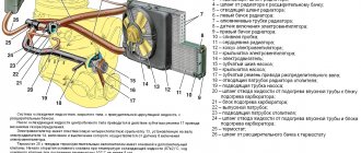
Hot antifreeze or antifreeze goes from the engine to the radiator. This element appears to be in the form of a heat exchanger with a large number of thin tubes and cooling fins to increase the contact surface. More details about the design, types and operating principles of radiators are described here .
The radiator is only useful when the car is moving. At this time, a counter flow of cool air blows over the surface of the radiator, resulting in heat exchange. Of course, its effectiveness depends on the ambient temperature, but while driving this flow is still much cooler than the engine coolant.
The principle of cooling operation is at the same time its disadvantage - maximum cooling is only possible when the car is moving (cold air must penetrate the heat exchanger). In urban environments, it is impossible to ensure a constant process due to traffic lights and frequent traffic jams in megacities. The only solution to this problem is to create forced air injection onto the surface of the radiator. The fan performs exactly this function.
When the engine temperature rises, sensors are triggered and the heat exchanger is blown. More precisely, the blades are configured so that the air flow is not supplied against its movement, but is sucked in. Thanks to this, the device is able to increase the radiator airflow even while the car is moving, and when the vehicle is stationary, fresh air enters the engine compartment, rather than using the hot environment near the engine.
In older cars, the fan was rigidly mounted on the crankshaft, so it had a permanent drive. If in summer such a process only benefits the power unit, then in winter excessive cooling of the engine is not beneficial. This feature of the constant operation of the device prompted engineers to develop an analogue that would work only when it was required.
How to check the fan sensor
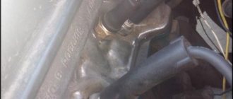
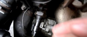
To check the functionality of the fan switch sensor, it must be removed from its seat. As mentioned above, it is usually located either on the radiator or in the cylinder block. However, before removing and testing the sensor, you must ensure that power is supplied to it.
Power check
Checking the DVV power supply
On the multimeter, we turn on the mode for measuring constant voltage within about 20 Volts (depending on the specific model of the multimeter). You need to check for voltage in the disconnected sensor chip. If the sensor is two-pin, then you will immediately see whether there is 12 Volts there. In a three-pin sensor, you should check the voltage between the terminals in the chip in pairs in order to find where there is one “plus” and where there are two “minuses”. Between the “plus” and each “minus” there should also be a voltage of 12V.
If there is no power to the chip, first of all you need to check whether the fuse is intact (it can be either in the block under the hood or in the car interior). Its location is often indicated on the fuse box cover. If the fuse is intact, you need to “ring” the wiring and check the chip. Then you should start checking the fan sensor itself.
However, before draining the antifreeze and unscrewing the radiator cooling fan sensor, it is worth conducting another small test to ensure that the fan operates properly.
Checking fan operation
Using some kind of jumper (a piece of thin wire), connect the “plus” in pairs and first one, and then the second “minus”. If the wiring is intact and the fan is working properly, then at the moment of the short circuit, first one and then the second fan speed will turn on. On a two-pin sensor there will be one speed.
It is also worth checking whether the fan turns off when the sensor is disconnected, and whether the contacts in it are stuck. If the fan continues to run when the sensor is turned off, this means that there is something wrong with the sensor and it needs to be checked. To perform this, the sensor must be removed from the machine.
Checking the fan switch sensor
You can check the DVV in two ways - by heating it in warm water, or you can even heat it with a soldering iron. Both of them involve checking for breaks. Only in the latter case will you need a multimeter with a thermocouple, and in the first - a thermometer capable of measuring temperatures above 100 degrees Celsius. If you are checking a three-pin fan switch sensor with two switching speeds (installed on many foreign cars), then it is advisable to use two multimeters at once. One is to test one circuit, and the second is to simultaneously test a second circuit. The essence of the test is to find out whether the relay operates when heated to the temperature indicated on the sensor.
Check the radiator cooling fan switch on sensor using the following algorithm (using the example of a three-pin sensor and one multimeter, as well as a multimeter with a thermocouple):
Checking DVV in warm water using a multimeter
- Set the electronic multimeter to the “diagnosis” mode.
- Connect the red probe of the multimeter to the “positive” contact of the sensor, and the black one to the “minus”, which is responsible for the lower fan rotation speed.
- Connect the probe measuring temperature to the surface of the sensor's sensitive element.
- Turn on the soldering iron and apply its tip to the sensitive element of the sensor.
- When the temperature of the bimetallic plate reaches a critical value (indicated on the sensor), a working sensor will close the circuit, and the multimeter will signal this (in the dialing mode the multimeter beeps).
- Move the black probe to “minus”, which is responsible for the second fan speed.
- As heating continues, after a few seconds the second circuit should close on a working sensor and when the threshold temperature is reached, the multimeter will beep again.
- Accordingly, if the sensor does not close its circuit during warm-up, it is faulty.
Checking a two-contact sensor is performed in the same way, only the resistance needs to be measured only between one pair of contacts.
If the sensor is heated not with a soldering iron, but in a container with water, then make sure that it does not cover the entire sensor, but only its sensitive element! As it heats up (control is carried out with a thermometer), the same operation will occur as described above.
After purchasing a new fan switch sensor, it also makes sense to check its functionality. There are a lot of fakes and low-quality products on sale these days, so checking won't hurt.
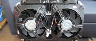
Design and types of fan
Despite its key importance for the cooling system, this mechanism has a fairly simple design. Regardless of modifications, the fan design will consist of three elements:
- The casing, which is the basis of the mechanism, is installed on the radiator itself. The peculiarity of this element is that its design forces the air flow to work in only one direction - not to dissipate upon contact with the heat exchanger, but to pass through it. This casing design allows for more efficient cooling of the radiator;
- Impellers. Each blade is slightly offset from its axis, like any fan, but in such a way that when they rotate, air is sucked through the heat exchanger. Typically this element consists of 4 or more blades;
- Drive.
Depending on the device model, the drive may have a different type. There are three main varieties:
- Mechanical;
- Hydromechanical;
- Electric.
Let's consider each modification separately.
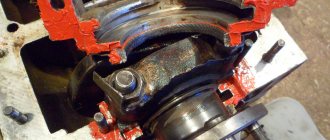
Mechanical drive
The mechanical drive has a simple device. Essentially, this type of fan has a permanent connection. Depending on the characteristics of the engine, it can be connected to the crankshaft through a pulley or through a timing belt. Starting the engine immediately leads to the operation of the impeller, and constant airflow is carried out on the heat exchanger and power unit.