Where is the gas 53 switch located?
In GAZ 53 it is located in the distributor. In contact ignition, the role of the breaker was performed by the cam shaft of the distributor and the ignition contacts; in a more modern version, the role of the breaker is performed by the Hall sensor. Switch.
Interesting materials:
How to store cranberries on the balcony? How to preserve lettuce leaves? How to preserve a small thuja in winter? How to store milk without refrigeration? How to save settings in the browser? How to store peeled new potatoes? How to save presets from telegrams to Lightroom? How to save a project in Adobe Photoshop? How to save progress in Hay Day? How to keep lettuce leaves crispy?
Automotive ignition system
Of course, in the VAZ-2109 car, and in other models as well, each system is very important, because it fulfills its main purpose, and failure of any system simply will not allow the car to perform its functions. Therefore, you need to monitor every system in your car, and, of course, the ignition system, without which the power unit will not be able to operate. Car owners should not consider the ignition system as a separate part, since it consists of several rather complex components, and one of the most important is the switch.
Quite often, car owners wonder: how can they check the VAZ-2109 switch and is it really possible to cope with this task on their own? We will try to understand these questions further.
Scheme and principle of operation of BSZ
We connect a 12 V light bulb instead of the coil.
For an analogue of the foreign microcircuit LB, see
To have an idea of what this gadget looks like and what to look for, you can look at a photo of the switch on our Internet portal.
They have contacts that can burn or simply wear out. The controllers also control the electrovalve of the economizer of forced idling EPHH. The use of semiconductor and microprocessor switches in contact-transistor or contactless ignition systems allows you to obtain the following advantages: the current flowing through the breaker contacts is reduced, as a result of which they practically stop burning for a contact-transistor ignition system; the duration of the spark supply increases, which guarantees effective ignition of the working mixture in the engine cylinders; it becomes possible to significantly increase the compression ratio in the engine cylinders, as well as the crankshaft rotation speed, without compromising the reliability of spark formation.
Choke L1 and resistor R1 are designed to speed up the process of closing transistor VT1, capacitor C1 of the primary excitation circuit of the ignition coil and capacitor C2 serve to protect the components of the switch circuit from voltage surges in the vehicle's on-board network. The protection circuit of the output transistor is made on discrete elements C7 and R. The voltage is supplied to the main distribution contact, then through the wiring it goes to the spark plugs, which form a spark.
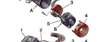
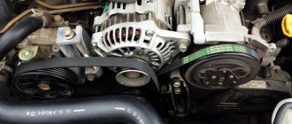
Check for a spark when the ignition is turned on. It is a hybrid of electronics and mechanics. The electronic part includes a commutator and a coil. A cover is attached to the top with latches, where the cables from the spark plugs are connected.
The distributor body should be turned to the desired position and secured with a nut. Tighten the distributor fastening nut, install the cap and spark plug, then start the engine. But with the help of spark plugs alone, the engine will not be able to run.
The spark plug cables are connected according to the numbering on the cover, the central wire is connected to the coil electrode. If there were no annoying errors during the installation process, the car will start immediately
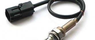
For comparison, look at the contact system. Checking the Hall sensor Measure the voltage at the sensor output
Repair and maintenance What is a switch in a car? Automotive electronics course. Switch
How to check a VAZ 2108-2109 switch
Warm Siberian greetings to everyone. I want to share with you that the switch is different from the switch. A new one, just from the store, may be worse in terms of parameters than the replaced old one, which was previously thrown into the trunk. I will also show how the switch is responsible for the power and duration of the spark.
After the release of my videos on YouTube on repairing, adjusting carburetors and diagnosing injection cars. I started getting a lot of questions. In order to communicate more closely with my subscribers and viewers, I began to conduct these streams. Subscribe. Press the bell. Ask your questions - I will be happy to answer them in more detail than in writing.
Sources
- drive2.ru/l/564176184837932184/
- vaz-russia.com/remont-vaz-2108/zamena-kommutatora-zazhiganiya-na-vaz-2108-vaz-2109-vaz-21099.html
- twokarburators.ru/kommutator-vaz-2108-2109-21099/
- ladaautos.ru/vaz-2109/kak-mozhno-proverit-kommutator-vaz-2109.html
Power check
In order for a spark to jump between the spark plug electrodes, the commutator capacitor must be charged from something. And it is charged either from a battery or from a generator. Means what? Right! We check whether power is supplied to the switch.
Before you start measuring power, let’s determine what type of switch is on your scooter. Visually, switches of the DC CDI type are twice as large as AC CDI. But this is not an exact criterion. The most accurate criterion is to look at the output of the high-voltage coil of the generator:
- If it is not activated, it means that your scooter is equipped with a DC CDI type switch
- If enabled, then vice versa - your scooter is equipped with an AC CDI type switch
The output of the high-voltage coil of the generator is located in the same place as the output of the generator itself: we are looking for where the wires coming from the generator are connected to the on-board network of the scooter and if one of the two wires with round terminals is not connected, then the coil is not activated
Breaker-distributor
The main faults are:
- wear and burning of contacts
- decrease in spring elasticity
- wear of the textolite bushing and heel of the breaker lever
- cracks or through spark breakdown of parts (cover, rotor)
Burnt contacts are cleaned with glass sandpaper or a special needle file, followed by wiping with a rag soaked in gasoline. If the contact height is less than 0.6 mm, replace the breaker lever or contact stand assembly. Instead of worn contacts, new ones are soldered using PSr-70 solder.
The spring tension is checked using a dynamometer. The spring force along the axis of the contacts at the moment of their rupture must be at least 4.9 N. The moment of contact rupture is determined by a test lamp. If the spring weakens, the breaker lever assembly is replaced.
In ignition timing regulators, damaged springs, diaphragms, fitting gaskets, and textolite parts are replaced with new ones.
In the assembled breaker-distributor, the roller should rotate easily, its longitudinal movement should not exceed 0.25 mm. The assembled breaker-distributor is adjusted and tested on the KI-968 stand. It is connected to the induction coil and battery of the stand. The average value of the current passing through the contacts of the breaker, other things being equal, depends on the angle of the closed state of the contacts, i.e., on the angle of rotation of the breaker cam, within which the contacts are in the closed state. At the stand it is controlled using the IUC device. The angle is checked at a cam rotation speed of 1500 rpm and adjusted by changing the gap between the contacts.
General faults
Malfunctions of the ignition system in general can be divided into the following categories:
- When the engine fails to start.
- When the engine does not develop full power.
- When there are interruptions in engine operation.
As for the first type, these are the following malfunctions:
- Damage to the wire connecting the ignition module and the power relay;
- Failure of the power relay;
- Oxidation or looseness of wire tips in the sockets;
- Insulation failure or contamination of wires;
- Changing the gap between the electrodes of the spark plugs or their oiling;
- Malfunction in the ignition module;
- Failure of the controller, as a result of which pulses stopped flowing to the module;
- Failure, incorrect installation or broken wires of the sensor that regulates the position of the crankshaft;
- Damage to the contact corner of the sensor;
- Current leakage due to cracks and burns that appear on the cover or sensor, as well as the accumulation of moisture and carbon deposits on the inside of the cover;
- Stopping the operation of the solenoid valve from the carburetor due to a break in the wire that connects it to the controller;
- Controller failure;
- Switch failure;
- Malfunction in the switch;
- Incorrect installation of the ignition element;
- Coil damage.
The second category includes the following types of main malfunctions of the ignition system:
- The ignition timing is incorrectly set.
- Weakening of the regulator spring or sticking of its weights.
- A change in the shape of the pulses on the primary winding of the commutator, which is one of the main reasons for its malfunction.
- Damage to the hose, the task of which is to connect the exhaust pipe and the absolute pressure sensor.
- Failure of the previously mentioned sensor.
- Fuel condensate settles on the walls of the hose.
- Stopping the controller from responding to changes in signals from the sensor.
- Malfunctions in the operation of temperature sensors.
- Damage to the wire connecting the controller and sensors.
And finally, the third category of general faults includes:
- Failure of the controller or ignition module;
- Damage, oxidation or loosening of high voltage wires;
- Oiling of candles, accumulation of soot on them and formation of cracks;
- Worn electrodes;
- Too early and late ignition;
- Formation of too large a gap between the electrodes of the spark plugs;
- Weakening the springs of the regulator weights;
- Worn contact corner;
- Damage to the sensor cover;
- Switch failure;
- Burning of the central contact of the rotor;
- The appearance of cracks, other damage and carbon deposits on the sensor cover and rotor.
These were the main malfunctions of the ignition system. Now in more detail about each system (contactless and electronic).
High voltage magneto
Starting engines installed on diesel engines have an autonomous high-voltage source - a magneto, which generates a low-voltage current, converts it into a high-voltage current and supplies it at a certain moment to the spark plugs.
The main magneto malfunctions are:
- rotor demagnetization
- damage to transformer windings
- breaker contact wear
- crack in parts of current-carrying devices
- capacitor breakdown
- violation of the magneto contour angle
The magnetization of the rotor is checked with an MD-4 magnetometer. If it is below 220 μWb, then the rotor is magnetized on the NA-5-VIM device from a 12-volt battery by turning on the device 2-3 times for 1-2 s.
The performance of the transformer is checked on the KI-968 stand with a current of 1.5-2.5 A, which is passed through its primary winding and the stand breaker. At a rotation speed of the breaker cam shaft of 500 min-1, a stable blue spark should appear on the three-electrode spark gap of the stand. The faulty transformer is replaced.
When the magneto is assembled, the rotor should rotate smoothly by hand and self-align into the neutral position, being moved away from it at an angle of 15-20°. Longitudinal movement of the rotor is allowed up to 0.06 mm. The gap between the open contacts of the breaker should be within 0.25-0.35 mm. The spring pressure at the moment of opening the contacts is 5-7 N. The outline is checked on the assembled magneto - the angle between the neutral position of the rotor (the rotor magnets are in a vertical plane) and the position of the rotor when there is a maximum current in the primary winding of the transformer; at this moment the breaker contacts should open. The outline size should be 8-12°. Violation of the outline setting leads to a decrease or complete cessation of sparking due to a decrease in the current in the primary winding of the transformer and the voltage in the secondary. To check the magnitude of the magneto outline, install it on the KI-968 stand, connect it to the drive, set the rotor to the neutral position, and rotate the arrester pointer to zero. Smoothly turning the magneto drive by hand in the direction of operating rotation, record the moment of opening of the breaker contacts (use the stand's IUC device or a test lamp). The outline is determined using the spark gap scale. Set the outline by turning the cam on the rotor neck.
The assembled magneto is tested for uninterrupted spark formation at a rotation speed of 2000-4500 min-1 for 5 minutes with a gap of 7 mm on the spark gap. The high-voltage insulation of the magneto is checked at a rotation speed of 2400-3000 min-1 and a gap on the spark gap of 9-11 mm for 15 s. During the test, sparking must be uninterrupted.
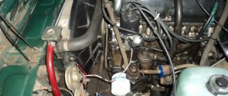
UAZ won't start? No spark?
There can be a great many reasons.
But if you have already checked the flow of gasoline into the carburetor, and from there into the engine, then most likely the problem is in the ignition system. The UAZ 469 is an extremely simple car and no complex electronic components start this engine. An old, harsh distributor and a non-electric fuel pump. That's all that runs the old 417 engine.
Let's look at one of the common problems with the ignition of the UAZ 469.
The old UAZ has this problem, the switch is in the passenger's feet.
If you haven't changed it yet, then most likely you will have to replace it soon. Or someone else has already changed it before you.
My 1991 car has had this switch since the factory.
Answers from experts
murzik99rus:
A switch is a device for matching something with something. A reel is a device with windings. By the way, the winch also has a reel.
Vladimir Bulanov:
the commutator supplies an impulse to the coil, the coil to the distributor and spark plugs
NN:
The coil is round with one thick wire and two thin ones, and the switch is square, aluminum, and many wires fit into it.
Ruslan:
A classic coil is an ordinary transformer with two windings: the primary winding works with the commutator and the secondary (boost) winding works with the spark plugs. A commutator is a device that, at the right moments, switches the current in the primary circuit of the ignition coil.
coil - creates high voltage commutator - designed to control the current of the primary winding(s) of the ignition coil
Alexander Kulikov:
On the ZIL 130, the switch is located on the left near the clutch pedal, and the coil, also known as the “bobbin” under the hood, is a cylindrical device topped with a truncated cone, from which protrudes a high-voltage wire that goes to the ignition distributor, colloquially a “distributor”
Denis Karpov:
A switch is an electronic device that controls the signal supplied to it. In a car, the switch controls the ignition coil using signals (pulses) that it receives from the sensor - the ignition distributor. The ignition coil is a step-up transformer, which turns 12 volts of the on-board network into 10,000 volts for the spark plugs. But since this is a transformer (converter), then the current in it must be either pulsed or alternating. The switch is responsible for the impulses.
Konstantin Salifov:
Switch is a device that distributes the spark supply torque among the cylinders. (Digital analogue of a trampler). The high-voltage coil significantly increases the voltage supplied to the spark plugs. The generator does not produce enough voltage to form a spark; a coil is needed for this.
Observer:
A switch is a device with which you can perform switching, that is, switching some incoming sources... For example: a telephone switch for 100 subscribers, a video switch, a microphone switch, etc.
Alexey Lobanov:
This relay is responsible for charging
Alexey Gerasimov:
SWITCH (from Latin commuto - I change) - an electromechanical, electronic or electron beam device (switch, switch, distributor) that provides selection of the required output electrical circuit and connection of the input circuit to it. The selection is made manually or automatically. The simplest electromechanical switches are switches, sets of electromagnetic relays, electromechanical finders. The switch is included in more complex devices, e.g. telephone exchange.
dixi2006:
A device (switch, distributor) that provides, by turning on, turning off and switching, the selection of the required output circuit (circuits) and the connection of the input circuit (circuits) with it,
ROMAN TISHAKOV:
Yuri Bulany:
The commutator in the auto-Hall sensor caught the window, generated a low-current signal, this signal went to the commutator, it amplified it in current, fed it to the coil, the coil - one end constantly sits during ignition (let's say +), the second end (minus) came from the commutator , there was a spark. That is, the switch is a current signal amplifier for the coil.
Andrey Lashch*****:
This is a rectangular piece of shit to which wires go with the magneto and from which they go to the coil and headlights
How to replace the ignition system switch on a VAZ 2108-VAZ 21099?
Removal: 1) First remove the negative terminal from the battery. (You can read how to do this in the article: “Replacing the battery”, in the “first” paragraph)
2) Then disconnect the wire block from the switch by hand.
3) Next, use a wrench to unscrew the two side nuts that secure the switch to the car body.
Note! There will be a ground terminal under the left nut, so when the nut is unscrewed, disconnect this terminal from the switch!
4) And at the end of the operation, when the block is disconnected and the two side nuts are unscrewed, remove the switch from the car.
Installation: 1) First, install the new switch in its place, and then tighten the side nuts that secure it.
Note! Before you start screwing the left nut, install the ground terminal in the place where it will be screwed first, and only after that screw the left fastening nut!
2) Next, insert the wire block into the connector of the new switch.
3) And then, finally, install the “minus” terminal that you removed earlier on the battery.
Checking the ignition system switch for serviceability:
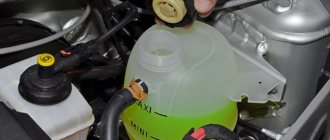
1) To do this, first disconnect terminal “K” from the ignition coil by unscrewing the nut that secures it with a wrench. (Be sure to read the “Important” paragraph at the end of the article).
2) Next, using a test lamp, which is designed for “12 Volts”, with a power of “3 W”, check the coil for serviceability for this:
- First, connect the previously disconnected terminal to the control lamp.
- And then connect the other contact that comes from the control lamp in place of the “K” terminals on the ignition coil.
- And then, turning the engine over with the starter, check whether the lamp lights up or not.
Note! If it does not light up, then replace the ignition coil with a new one!
Important! On the very first ignition coils, instead of the “K” marking, the “+” marking was drawn, and therefore, if this is the case on your coil, then in this case, disconnect the wire next to which the “+” marking is located and not “K”!
Active forum discussions
What problems with the spark plugs are you talking about? When connecting the coil to the car’s ignition system, in principle, you should not have any difficulties if, during preliminary dismantling, you marked or remembered which wires are connected where.
The rotor is a ring permanent magnet with four-pole cages tightly pressed to it from above and below, rigidly fixed to the sleeve. To do this, you can use an indicator screwdriver.
People who are too lazy to read the Kama Sutra and think with their heads often ask the question: “Then why is there a mark on the crankshaft pulley, if not for a strobe light? Switch The switch is designed to provide a powerful impulse regardless of engine crankshaft speed, thereby facilitating ignition of the fuel mixture. The capacitor in the breaker is no longer needed; it can be turned off - one less weak point.
Double switches are available for all systems: with a variator, without a variator and with a Hall sensor. People who are too lazy to read the Kama Sutra and think with their heads often ask the question: “Then why is there a mark on the crankshaft pulley, if not for a strobe light? Has one output. The rotor is a ring permanent magnet with four-pole cages tightly pressed to it from above and below, rigidly fixed to the sleeve. That's all. Checking the Hall sensor and switch: 1.
Ignition system
The unnamed terminal of the coil is connected to the short-circuit terminal of the commutator and the commutator to ground.
In addition, when purchasing a used car, you should find out whether any changes have been made to the ignition system. Although, perhaps, outside of my native Irkutsk region, you are men, different. The IT pulse transformer serves to speed up the turn-off of the transistor when the breaker contacts open. Return to contents Cost of replacing the ignition system As you can see, the GAS ignition system consists of many components. Therefore, when replacing or performing repairs, you must follow safety regulations. The stator has an insulated stranded lead connected to the sensor lead. The ignition coil is of a cylindrical type; in older ignition systems the BB model was used. Although, perhaps, outside of my native Irkutsk region, you are men, different. Photos GAZ Burnout of the distributor cover often occurs due to a loose connection of the central high-voltage wire with the distributor cover.
The IT pulse transformer serves to speed up the turn-off of the transistor when the breaker contacts open. Output terminal on the primary and secondary windings; Center terminal spring; External insulation on the primary winding; Mounting bracket; External magnetic circuit and core. The reason may also be hidden in the electrical wiring: in particular, due to a damaged wire running from the switch to the ignition coil. There is also an ignition coil B. As you noticed, it looks no different from B. Some people install it; it is also suitable for GAZ, but I personally do not advise you to install it. Electrical wiring for 270 rubles. Or how to start the engine without a scooter
What is port recycling?
Network communication channel utilization is the percentage of time during which a communication channel transmits signals, or otherwise, the proportion of communication channel capacity occupied by frames, collisions and interference.
Interesting materials:
What should be included in the conclusion of the project? What should a court decision contain? What do beneficial bacteria eat? What is in the lithosphere? What's in Vegas? What kind of Viber program is this? What develops during adolescence? What is the penalty for using other people's photographs? What was one of the reasons for the defeat of whites in the Civil War? What is fard in prayer?