Ignition systems for gasoline engines of domestic passenger cars VAZ-2108, VAZ-2109, ZAZ-1102 contain an electronic switch. It is designed to generate current pulses in the circuit of the primary winding of the ignition coil.
In domestically produced electronic switches (series 3620.3734; 36.3734; 78.3734), the functions of the output current switch are performed by a powerful transistor, and the functions of controlling the parameters of current pulses (normalizing the duty cycle of triggering pulses, software regulation of the time of energy accumulation in the ignition coil, limiting the current level in its primary winding and amplitude of primary voltage pulses) is performed by a low-current electronic circuit, often in an integrated design.
The first domestic electronic switch with controlled parameters of ignition pulses (series 36.3734) was developed for the VAZ-2108 car. The switch used the K1401UD1 microcircuit, a powerful key transistor KT848A and other domestically produced elements.
The input information signal for the switch is the signal from the Hall sensor located on the ignition distributor shaft. Using this signal, the switch receives information about the number of engine revolutions and the position of its crankshaft. The switch is designed to work with a serial ignition coil 27.3705.
The switch was a prototype for the development of subsequent series, which have several design and circuit design options. However, what domestic switches still have in common is a combined integrated-discrete assembly technology, which makes them repairable.
Modern domestic switches use specialized output key transistors of the types KT890A, KT898A1, BU931 (foreign) in several designs: TO-220, TO-3, unpackaged. Some switches, for example 78.3734 (Fig. 4), use a four-channel operational amplifier of the K1401UD2B type as a control chip.
The switches also widely use the L497B control chip from SGS-TOMSON (domestic analogue of the P1055HP1). The block diagram and the recommended option for its inclusion are shown in Fig. 1, and the assignment of the pins is in table. 1.
Before you begin troubleshooting and repairing the electronic switch, you should: • check the integrity of the vehicle wiring, the reliability of the contact connections of the ignition system, the serviceability of the ignition system elements (spark plugs, ignition coil, Hall sensor, high voltage wires); • check the serviceability of the car generator, as well as its integrated voltage regulator; • check the supply of voltage from the on-board network (with the ignition switch on) to contact “P” of the Hall sensor connector.
The signs that indicate malfunctions of electronic switches, the most likely causes of these malfunctions and methods for eliminating them are summarized in table. 2.
Schematic diagrams of the ignition switches are shown in Fig. 2 (switch 3620.3734 – I), fig. 3 (switch 3620.3734 - II) and fig. 4 (switch 78.3734).
In conclusion, the following should be noted:
1. A close analogue of the foreign transistor BU931 (see diagrams in Fig. 2 and 3) is the domestic KT898A1. These transistors have a wide range of parameters, which leads to the need to select the ratings of radio elements in its base and emitter circuits for each individual transistor.
2. Resistors R7 (see Fig. 2) and R6 (see Fig. 3) are used to set the required current value through the powerful key transistors of the described switches.
Increasing the resistor value leads to a decrease in current and vice versa. Thus, by changing the values of these resistors, you can select the optimal current and thermal operating conditions of the output key transistors.
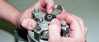
3. When replacing a powerful switching transistor, you should pay attention to the quality of fastening the transistor to the radiator (case) of the switch. They also check the presence of heat-conducting paste between the transistor and the radiator (switch housing).
4. An analogue of the foreign zener diode 1N3029 (see Fig. 3) is the domestic KS524.
5. An analogue of the foreign microcircuit L497B (see Fig. 1, 2, 3) is the domestic KR1055ХП1.
6. After replacing faulty radio elements in the switch, each new element on the board and its soldering area should be coated with nitro varnish. When assembling the switch housing, its cover around the perimeter of the seal must be coated with a waterproof sealant (for example, Germesil).
The switch is an electronic component to ensure the operation of a contactless ignition system. It is transitional between contact and microprocessor. The latter, the most advanced, allows you to control the torque using data read from sensors - oxygen, speed, engine speed and others. But there are still many cars on the roads that have both contact breakers and contactless ones. Therefore, for maintenance and diagnostics, you need to know the purpose of all elements, as well as troubleshooting methods and their main symptoms. Before testing the switch, review all parts carefully.
Contactless ignition system
In total, there are three huge groups of systems - contact, contactless, microprocessor. The first is divided into two subgroups - contact and using a transistor operating in switch mode. Transistors are also used in the design of a contactless ignition system. This scheme began to be actively used in the early 80s of the last century. And it has a number of advantages, which will be discussed below. The switch circuit is simple; it can be implemented both on transistors and on a controller.
But the contactless ignition system also has many disadvantages when compared with a microprocessor one. The latter allows you to control almost all engine parameters. BSZ does not allow this; it also cannot be used normally on injection engines. The reason for the obsolescence of the contactless system lies not only in the development of electronics and the automotive industry, but also in the adoption of stringent measures to ensure the environmental friendliness of internal combustion engines. Unfortunately, only microprocessor control can reduce the amount of harmful substances in the exhaust.
Main elements of the system
Of course, the first thing to mention is the spark plugs. They are installed in the cylinder head, the electrodes come out from the inside. These are the elements that allow the air-fuel mixture to ignite. But with the help of spark plugs alone, the engine will not be able to run. It is necessary to monitor the position of the crankshaft in order to know in what position the pistons are in the cylinders.
For this purpose, an inductive sensor operating on the Hall effect is used. It is part of the design of another element - the ignition distributor. The sensor produces a pulse that is sent to the switch. This device allows you to amplify a weak signal to a voltage of 12 volts, and then apply it to a coil. A coil is nothing more than a simple transformer (step-up). Its secondary winding has a greater number of turns than the primary. Due to this, the voltage increases and the current decreases. The voltage in the BSZ is supplied to the spark plugs at a value of 30-35 kV (depending on the car model).
SZ scheme
The ignition system used on the VAZ 2109 includes the following components:
- Switch;
- Candles;
- Distributor sensor;
- Ignition coils;
- Switch;
- Locking device. It does not allow the starter to turn on until the ignition is completely turned off;
- Locking and anti-theft device;
- Hall Sensor;
- The sensor-distributor roller, which is located horizontally and receives torque from the camshaft;
- System of spontaneous ignition shutdown, which is activated after 2-8 seconds;
- Switched current equalization system, which is required when the network voltage changes within the range of 6-18V;
- The system built into the switch, which regulates the time of energy accumulation in the coil, limits the current strength at low motor operating frequencies.
The ignition system operates with a voltage of up to 26 kV, the spark charge has a duration of 1.6-2.0 milliseconds, and the energy released during this time is 35-50 MJ.
Service
If you do not monitor the state of the system and lose sight of the presence of malfunctions and malfunctions, this can lead to certain consequences. Namely:
- Reduced reliability of the operation of the protective equipment, the occurrence of failures;
- Reduced technical characteristics of the engine, such as acceleration dynamics, maximum speed;
- A sharp increase in the amount of fuel consumed;
- Failure of SZ elements or the entire system.
How is BSZ better than contact?
Having carefully read the previous section, you can see that the system uses an inductive non-contact Hall sensor. The advantage is obvious - there is no friction and commutation. For comparison, look at the contact system. In it, the breaker switches the voltage, the value of which is 12 Volts. Whatever one may say, the metal contacts are constantly in contact with each other, gradually wear out, and become covered with soot.
For these reasons, it is necessary to constantly monitor the breaker, adjust the gap, and carry out timely replacement. BSZ is devoid of these shortcomings, therefore, without third-party intervention, the system operates much longer. The Hall sensor fails very rarely, as does the switch. This increases the reliability of the system, but precautions must also be taken, in particular, the connection of the switch to the body must be as tight as possible to ensure effective heat exchange. In addition, BSZ allows you to improve engine performance, increase, albeit slightly, its power, along with increasing reliability.
How does a switch work?
Essentially, a switch is a simple signal amplifier. It can even be compared to a Darlington assembly, which is used in microcontroller technology to convert a weak signal from an output port to the required level. The basis of this assembly is field-effect transistors operating in switch mode. An operating voltage is applied to them, a signal is sent to the control terminal, which is amplified and removed from the collector.
The ignition switch has an almost similar operating scheme. Only the signal from the Hall sensor is used. It has three outputs - control, common, plus power. When a metal plate appears in the sensor area, a current is generated, which is supplied to the input of the switch. Next, the signal is amplified and supplied to the primary winding of the coil. The entire system is powered only after the ignition is turned on (after turning the key).
Electronic ignition switch - the next step in development
The simplest and most obvious option is to use transistor switches to control the currents flowing through the ignition coil. This is how the electronic voltage switch appeared. A diagram of such a simple device is shown below:
The commutator does not affect the original operating principle based on electromagnetic induction. The role of electronic switches, which are used as transistors VT1 and VT2, is to reduce the load on the contacts of breaker S1 and increase the current flowing through the winding of coil L1. The consequence of this technical solution was:
- increasing the reliability of the entire ignition system;
- ensuring the possibility of its operation at high engine speeds and at high speeds;
- increasing the compression ratio.
Basic Switch Elements
The switch circuit is quite simple, but making this unit yourself is pointless, since buying a ready-made version will be much easier. Installation must be carried out as competently as possible, otherwise the device will not operate correctly. In addition, when using transistors, you need to carefully select them according to their parameters, and for this you need to have high-quality measuring equipment. Unfortunately, for two identical semiconductors, the spread of characteristics can be very large. And this affects the operation of the device.
The VAZ switch, designated 76.3734, consists of one main element - the L497 controller. It is designed specifically for use in contactless ignition systems. The domestic analogue of this controller is KR1055HP2. Their parameters are almost identical, which allows you to use any of the controllers. In addition, this chip allows you to connect a tachometer located on the dashboard of the car. But you can also use a simpler circuit, which is an amplifier unit of two stages. True, the reliability of such a device is much lower.
What is and what is the principle of operation of the ignition switch
Even on the very first cars, battery ignition systems were used to ignite the combustible mixture, the functional diagram of which is shown in the figure.
This figure allows you to understand that its work is based on the principle of self-induction. When the current flow circuit in the winding of bobbin 3 is broken, a high-voltage EMF is induced in the secondary, causing a spark to appear on the contacts of spark plug 2. The circuit break is caused by the opening of the contacts of breaker 6.
Without touching on the advantages or disadvantages, it should be noted that this scheme worked on the car for a long time. And only the emergence of a new element base gave impetus to the further development of such a device, preserving the original principle of its operation.
Connecting the switch
Cases vary, and it is possible that you will have to change the wiring. Therefore, you will need to take into account the purpose of all pins on the switch plug. This will allow the connection to be made correctly, and there will be no risk of damaging it. The first pin of the switch is the output. In other words, the amplified signal is removed from it. It must be connected to the terminal of the “K” coil. The second contact is connected to ground - the negative of the battery.
All three wires from the Hall sensor go to the VAZ switch. Moreover, the signal wire is connected to the sixth terminal of the switch. The fifth is the power output (the voltage on it is stable 12 Volts). The third output of the switch is ground (minus power). The third is connected inside the block to the second. But between the fourth, which is supplied with power from the battery, and the fifth there is a constant resistance and a voltage stabilizer.
Wiring diagram for VAZ-2109 carburetor
- Headlight.
- Electric motor for headlight glass cleaning system. An optional part, used mainly on export vehicles.
- Limit switch for powering the engine compartment lamp.
- Klaxon.
- An electric motor drives a fan installed on the radiator of the cooling system.
- Temperature indicator that provides a control signal for the electric drive of the fan impeller.
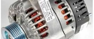
- Alternator.
- Fluid supply valve for headlight glasses. Used in conjunction with paragraph 2.
- Fluid supply valve for the glass of the fifth door.
- Fluid supply valve to the front glass.
- Spark plugs.
- Hall sensor used to distribute ignition pulses.
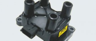
- Coil.
- Limit switch for reverse gear lights.
- Fluid temperature meter in the cooling system.
- Starter.
- Accumulator battery.
- A sensor that measures the fluid level in the brake booster.
- Switch that controls the ignition system.
- Sensor for determining the position of the top dead center of the piston of the first cylinder. Installed on some export VAZ 2109 with a diagnostic system. Found only on cars before 1995.
- Diagnostic block. Optional element, installed together with item 20.
- Controller for controlling the solenoid valve installed in the carburetor.
- Starter switch contact block.
- Limit switch on the carburetor.
- Economizer valve.
- Sensor signaling an emergency decrease in oil pressure.
- Washer pump drive.
- Fan impeller motor for ventilation and heating systems.
- Resistance providing additional fan speeds.
- Speed shifter.
- Windshield wiper drive.
- Cigarette lighter.
- Illumination system for levers for adjusting heater operating parameters.
- Socket for additional equipment.
- Lamp for auxiliary lighting of the engine compartment.
- Illumination system for the glove box on the instrument panel.
- Relay and fuse link mounting block.
- Instrument panel light switch.
- Parking brake lamp limit switch.
- Brake lamp limit switch.
- Steering column switch lever block.
- Exterior lamp switch.
- Hazard switch.
- Turn on the rear fog lamp.
- Bimetallic fog lamp fuse.
- Heated glass switch on the fifth door.
- Turn signal repeaters on the front fenders.
- Central interior lighting.
- Individual lampshade.
- Switches for backlight operation on the middle pillars.
- Ignition switching unit.
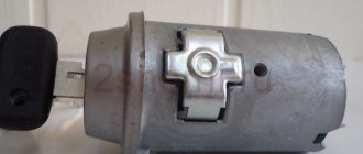
- Egnition lock.
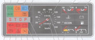
- “Low” type instrument cluster.
- Choke limit switch on the carburetor.
- Rear lights.
- Fuel level meter in the tank.
- Heated glass.
- Rear wiper drive.
- Two lamps for room illumination.
How to check
There is nothing complicated in this procedure. The easiest way is to use a known-good node, since you can check the switch this way in literally a matter of minutes. But if there is none, and you need to determine exactly whether the fault is in the coil or in the switch, it is wiser to use other methods. You will need a simple incandescent lamp. If you don’t know where to get it, then unscrew it from the interior lamp or from the side lights.
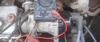
Connect one terminal of the lamp to the negative of the battery. Connect the second one to pin “1” of the switch. This is the same pin from which the amplified signal is removed. If the lamp lights up, then the device is working properly. A more advanced testing method is carried out using an oscilloscope. On the screen you can see the magnitude and shape of the signal, and also compare it with the reference one.
Oil pump work
Lubricant supplied through the oil pump extends engine life. To improve the performance of the oil pump when tuning the Niva engine, you need to take another pump and cut off part of the housing with the parting plane from it. The thickness of this “pancake” should be about 11 cm. Using milling, cut off the excess and leave a thickness of 10 mm.
Next, do the following to remove chamfers on the edges of the teeth:
- We compress, that is, remove, the drive gears.
- We trim one of the gears by 0.75 mm on each side.
- We cut the second gear to 11.5 mm (after trimming).
- We repeat the operation with the remaining gears (driven).
Let's start working on the body. To do this we do the following:
- We release the driven gear axis from the housing.
- We form a longer axis from the drive roller.
- We insert the resulting axle into the body.
- We press the narrow gear onto the second drive shaft.
- Press on the wide gear.
- We fix the wide driven gear in the housing.
- We install a narrow gear into the housing.
This sequence will prevent the gears from turning relative to each other. You can also improve the oil receiver of the Vase by cutting it a centimeter from the bottom. After this, we adjust the end gap and connect the entire structure with bolts.
Ignition settings
When setting up the ignition, you will need to do the most important thing - install the shafts according to the marks so that the gas distribution functions synchronously with the operation of the piston group. This is the first thing you should do before you start adjusting the ignition. It is worth noting that there should not be any particular difficulties during setup, especially on VAZ 2108-21099 cars. The thing is that the ignition distributor on the engines of these machines can only be installed in one position. Moreover, the ignition switch does not undergo any settings during this procedure, since it does not have any.
The distributor body rotates around its axis to make more precise adjustments. And this turns out to be enough. To accurately set the torque, you can use a simple circuit that uses a simple LED as an indicator. The Hall sensor is disconnected from the system, and positive power is supplied to its negative terminal. An LED is switched on between “+” and the signal LED, and a 2 kOhm resistance is connected in series with it to reduce the voltage. But the plus of the Hall sensor is connected to ground. Now all that remains is to slowly rotate the distributor housing. The moment when the diode lights up will be the desired one.
Pinout, connection diagram and check of the VAZ ignition coil
Today we will look at the design and diagrams of ignition systems for VAZ cars of all major models. Since carburetor versions of VAZ are practically history, we will dwell in detail on the ignition systems of injection cars. Their ignition system is based on an electronic ignition module. We also recommend that you carefully consider the choice of spark plugs and the quality of high-voltage wires, because the quality of the spark and, accordingly, the operation of the ignition system as a whole will depend on them. The information is intended as a reference guide for self-repairing a car.
conclusions
Many advantages are provided by such a simple unit in a contactless ignition system as a switch. This includes an increase in power, even if only slightly, a reduction in fuel consumption, and a significant improvement in the engine in terms of reliability. And most importantly, there is no need for constant monitoring and timely adjustment of the system. The modern driver does not want to repair a car, he needs a means of transportation. Moreover, it is reliable and will not let you down at the most crucial moment. Regardless of which switch is used in the BSZ, its efficiency is much higher than that of a contact breaker.
The VAZ 2108 switch provides the formation of control pulses supplied to the ignition coil. This element of the vehicle's electrical equipment is an electronic device that ensures the normal functioning of the vehicle's contactless ignition system.
This component of the vehicle's electronic ignition system is surface mounted and is robust enough to withstand the high vibration and shock loads that may occur during vehicle operation. The device implements the maximum possible protection options for electronic components.
Switch Specifications
The VAZ switch circuit is based on the L497 microcircuit, which controls the output NPN transistor. A special feature of the microcircuit is the ability to program the recovery time of the delay coefficient, which is important for trouble-free starting of a cold car power unit. This feature of this electronic component of the switch allows for rapid acceleration of the crankshaft speed without failures in operation, which ensures constant engine traction.
Analogues that are sometimes used in the design of the VAZ 2108 switch are the KR1055HP1, KR1055HP2, KR1055HP4 microcircuits. However, these electronic components are found quite rarely in the design of the device. Main technical parameters of the device:
- optimal operating voltage 13.5 V;
- voltage range for normal operation 6-16 V;
- switching current 7.5-8.5 A;
- the range of ensuring uninterrupted sparking is from 20 to 7000 crankshaft revolutions.
How to recognize switch faults
Ignition problems are always accompanied by characteristic symptoms that every car owner should be aware of. One of these faults is related to the switch.
Here are just the most common signs indicating problems with the operation of the VAZ 2108 switch.
- The engine cannot be started.
- The starter actively turns the engine flywheel, but there is no spark.
- The engine can be started, it idles, it can be raised to medium speeds, but it is impossible to increase the speed to maximum.
- The motor is not running at full power.
- At idle, the engine runs fine, but begins to stall when trying to start.
- The engine can be started, but it stalls after a short time.
- One of the cylinders refuses to work at a certain speed (troit).
- The engine stalls when hot and continues to run normally when it cools down.
- The battery discharge lamp is on.
- The tachometer shows sharp jumps in engine speed.
These are just the most common, but not the only features of a faulty switch. There are also a number of indirect signs. Sometimes even experienced technicians cannot immediately identify the symptoms of malfunction of this unit of the VAZ 2108 ignition system.
How to test a switch
On average, the cost of this part is not too high, but many car owners, for various reasons, do not seek to replace it. In addition, if you change a known-good switch, problems with the engine will remain, because the cause of malfunctions in the operation of the power plant may be completely different. Therefore, the optimal solution would be to check the part for functionality.
For accurate diagnostics, you will need special professional equipment, which is available at any service station. On a special stand you can check the pulse on the ignition coil, its stability and cyclicity. However, it is not always possible to turn to specialists; there is also a simpler folk diagnostic method. To check, you should take a key for an 8 and 12-volt light bulb with a power of 3 W. The algorithm of actions is as follows.
- Disconnect the power supply by disconnecting the terminals from the battery.
- Using a key number 8, you need to disconnect the brown wire that goes from terminal K on the ignition coil to terminal 1 on the switch.
- One contact of the control light is connected to the terminal on the ignition coil, and the other to the switch. As a result, the control lamp becomes part of the circuit between the coil and the switch.
- Connect the terminals to the battery and try to start the engine (the lamp should light up while the starter rotates).
A light that comes on indicates that the switch is working properly. If this does not happen, the unit is faulty and needs to be replaced. When disconnecting the light bulb, be sure to disconnect the negative terminal from the battery, thereby preventing the possibility of an accidental short circuit.
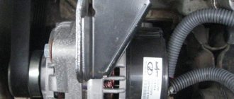
The installation location of the device is a partition separating the engine compartment of the car from its interior. The device is mounted in the engine compartment. The connection diagram of the switch must ensure reliable contact between the base of the device and the car body. The device can operate normally up to a heating temperature of 115 °C.
High voltage magneto
Starting engines installed on diesel engines have an autonomous high-voltage source - a magneto, which generates a low-voltage current, converts it into a high-voltage current and supplies it at a certain moment to the spark plugs. The main magneto malfunctions are:
- rotor demagnetization
- damage to transformer windings
- breaker contact wear
- crack in parts of current-carrying devices
- capacitor breakdown
- violation of the magneto contour angle
The magnetization of the rotor is checked with an MD-4 magnetometer. If it is below 220 μWb, then the rotor is magnetized on the NA-5-VIM device from a 12-volt battery by turning on the device 2-3 times for 1-2 s.
The performance of the transformer is checked on the KI-968 stand with a current of 1.5-2.5 A, which is passed through its primary winding and the stand breaker. At a rotation speed of the breaker cam shaft of 500 min-1, a stable blue spark should appear on the three-electrode spark gap of the stand. The faulty transformer is replaced.
When the magneto is assembled, the rotor should rotate smoothly by hand and self-align into the neutral position, being moved away from it at an angle of 15-20°. Longitudinal movement of the rotor is allowed up to 0.06 mm. The gap between the open contacts of the breaker should be within 0.25-0.35 mm. The spring pressure at the moment of opening the contacts is 5-7 N. The outline is checked on the assembled magneto - the angle between the neutral position of the rotor (the rotor magnets are in a vertical plane) and the position of the rotor when there is a maximum current in the primary winding of the transformer; at this moment the breaker contacts should open. The outline size should be 8-12°. Violation of the outline setting leads to a decrease or complete cessation of sparking due to a decrease in the current in the primary winding of the transformer and the voltage in the secondary. To check the magnitude of the magneto outline, install it on the KI-968 stand, connect it to the drive, set the rotor to the neutral position, and rotate the arrester pointer to zero. Smoothly turning the magneto drive by hand in the direction of operating rotation, record the moment of opening of the breaker contacts (use the stand's IUC device or a test lamp). The outline is determined using the spark gap scale. Set the outline by turning the cam on the rotor neck.
The assembled magneto is tested for uninterrupted spark formation at a rotation speed of 2000-4500 min-1 for 5 minutes with a gap of 7 mm on the spark gap. The high-voltage insulation of the magneto is checked at a rotation speed of 2400-3000 min-1 and a gap on the spark gap of 9-11 mm for 15 s. During the test, sparking must be uninterrupted.
Checking and replacing the device
When checking and repairing a car’s contactless ignition system, it is imperative to check the functionality of the switch. To test this device, you need to have a standard set of tools on hand. In addition, you will need a control light with a voltage of 12 V.
A full check of the element is carried out on a specialized stand, which allows not only to determine the presence of an impulse, but also its duration. Using a test lamp makes it possible to determine the presence of only a pulse when testing the device at home. To check the operation of the switch, you need to do the following operations.
- It is necessary to de-energize the vehicle's on-board network. This is done by disconnecting the negative terminal of the battery from the electrical circuit.
- Using an open-end wrench No. 8, terminal “K” is disconnected on the ignition coil, which has a red-brown wire connected to terminal “1” of the contact block of the switching device.
- The disconnected wire is connected to its terminal on the ignition coil through a light bulb, after which the negative terminal of the battery is connected to the on-board network. When the starter is turned on, the lamp should flash. The absence of blinking indicates that the switch is faulty.
When operating a car, in order to avoid failure of the switch, it is necessary to periodically clean the surface of the cooling radiator.
Video on repairing KZ VAZ
Every owner of the VAZ 2109 should know the ignition circuit Without knowing this circuit, you will not be able to start the car in case of ignition problems. Moreover, this scheme is elementary simple. The VAZ 2109 is equipped with a contactless ignition system. It consists of the following components: switch, ignition coil, distributor, Hall sensor, high-voltage wires and spark plugs. The task of the ignition system is to provide a timely, cyclic spark to the engine cylinders. Let's take a closer look at how the clamping circuit works.
Ignition circuit for VAZ 2109
ignition of the VAZ 2109: power is supplied to the ignition system through a relay. Until the key is in the ignition position, the relay will not turn on and supply power to the circuit. As soon as the key is turned, the ignition system is energized. +12V power from the battery is supplied to contact B of the ignition coil, the 4th contact of the switch. The Hall sensor powers the switch itself. Please note that the ignition relay is powered through the mounting block, and if there is poor contact in connectors Ш1, Ш8 or for some reason the track oxidizes or burns out, the ignition system will not be powered and the VAZ 2109 will not start. In order for a spark to begin to form, you need to crank the engine crankshaft. Together with it, the camshaft will turn and the Hall sensor will send an impulse to the switch. The commutator, in turn, will connect contact K of the ignition coil to ground, resulting in a spark appearing on the central wire. When the distributor slider connects the central wire and the wire leading to a specific engine cylinder, a spark will jump on the spark plug, igniting the combustible mixture. The engine will start. When it is necessary to turn off the engine, the driver, by turning the key in the ignition switch, turns off the relay, which in turn disassembles the power supply to the system. The switch and ignition coil become de-energized and stop working. The most common malfunctions of the VAZ 2109 ignition system: 1) Failure of the switch. 2) Failure of the Hall sensor. 3) Poor contact of the slider in the distributor. 4) Lack of power supply to the ignition system of the VAZ 2109. Go to Home.