01/25/2022 3,661 Alarms
Author: Victor
The Starline A91 manual includes sections on installing and operating the security system, including a guide to programming the key fob, autostart, and more. With its help, you can independently configure and adjust parameters in order to use all the capabilities of the alarm.
[Hide]
Specifications
Description of the properties of the Starline A91 car alarm:
- the carrier frequency value when transmitting pulses is from 433.05 to 434.79 MHz;
- the number of frequency channels used to control the security system with auto start is 128;
- the range of reception of pulse signals in the mode of transmitting commands from the key fob to the microprocessor module is 800 meters;
- the radius of operation of the anti-theft installation is 2 km in the mode in which messages are received from the control unit to the communicator;
- the maximum operating range of a spare pager that is not equipped with a display is 15 meters;
- The shock and tilt sensor belongs to the category of piezoelectric devices;
- the operating temperature range at which the security installation can perform its functions is from -40 to +85 degrees;
- the voltage value in the on-board network for powering the anti-theft system is from 9 to 18 volts;
- When operating in protection mode, the car alarm should consume no more than 15 mA of current.
The Autokasta channel briefly talked about the capabilities and characteristics of the A91 model anti-theft systems.
Installation and connection algorithm
Let's consider the installation points of different alarm components.
Features of installing the control unit
- The location for attaching the block is chosen to be hidden and protected from moisture;
- It is better to disassemble the center console, installing the unit behind the dashboard;
- Secure the block with hardware or plastic clamps;
- Install the ECU with the connector facing down so that water does not penetrate into the chip.
Features of siren installation
- Installed under the hood so that the module is not exposed to moisture or exposed to high temperatures;
- Install so that an attacker cannot get to the module or wiring from the bottom of the car;
- The module is mounted with the horn facing down;
- The wires are laid inside the cabin.
Features of installing additional elements
Shock and sensitivity sensors are mounted inside the passenger compartment in the middle of the body;
- Do not install gaskets between the shock sensor and the surface, because the device may not operate correctly;
- A device that controls the temperature of the cabin is mounted inside;
- The blocking relay is installed in the ignition switch;
- The Valyat key is safely hidden;
- The limit switches are fixed on the hood and doors.
Features of installing the antenna adapter
- The module is attached to the windshield as high as possible;
- There should be no metal elements or electrical appliances nearby, because they distort the signal;
- The surface is cleaned before fastening.
Laying wires
- The wires are connected according to the instructions;
- The wiring must be protected from the eyes of an intruder;
- The wires are laid so that moving body elements do not affect their operation in any way;
- The cables are insulated or equipped with heat-shrinkable tubing.
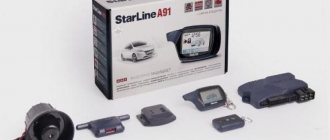
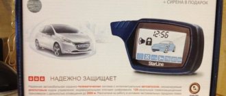
Equipment
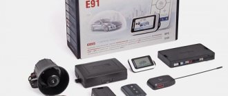
Overview of the elements that are included in the Starline Twage or Dialog security installation kit:
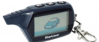
- A key fob that allows you to program and configure the anti-theft system. It is equipped with a display, thanks to which you can simplify control and ensure the functioning of two-way communication.
- Service instructions Starline A91, which indicate the main nuances regarding installation and adjustment of parameters.
- Guide to using the system.
- Rechargeable battery designed for installation in a communicator. Belongs to class AAA devices.
- Spare communicator. This device does not have a screen, nor does it have two-way communication options.
- A microprocessor unit designed to process and execute commands sent from the remote control.
- Antenna module.
- Two-level sensitivity and shock sensor.
- Double-sided tape for securing the transceiver during installation.
- Protective case for installing the main communicator with display.
- Power cable for connecting the antenna adapter.
- A cable designed to connect the shock and tilt sensor to the microprocessor module.
- Limit switch for mounting on the hood of a car.
- A service button designed for emergency control of the alarm and entering emergency mode.
- Temperature sensor. Designed for installation on a car engine so that you can start the car's power unit remotely in accordance with a certain temperature.
- The main wire, equipped with an eighteen-pin connector. Designed to connect the main elements of the anti-theft installation.
- Power cable for power supply and electrical circuits. Required to remotely start the car engine.
- Conductor for connecting to the car's central locking system. It is equipped with a 6-pin header.
- Signal status LED light, used to monitor the system.
The alarm package includes only one push-button switch. The remaining switching devices for mounting on the doors and luggage compartment must be purchased separately.
The Access Auto channel spoke in detail about the configuration of the Starline A91 anti-theft systems.
What will you need to install a Starline alarm system?
Tools that need to be prepared to install a car security system:
- side cutters;
- two screwdrivers - with a Phillips and a flat tip;
- stationery knife or scissors;
- soldering iron with consumables;
- a set of wrenches or socket wrenches (you need to assess in advance which panels and fasteners will have to be disconnected);
- tester - voltmeter or multimeter;
- an industrial hair dryer; if you don’t have one, you can use a lighter;
- drill with a set of drills;
- magnifying glass;
- 12 volt light bulb, better to use LED.
When installing a Starline car alarm, the wires that come as standard may not be enough.
Therefore, in addition to a set of tools, it is necessary to prepare consumables:
- a set of heat-shrinkable elements that perform the function of electrical tape and are cambrics that shrink in size when heated;
- a set of additional wires, the cables must be multi-core and have PVC insulation;
- active non-acid flux;
- a set of self-tapping screws of different lengths will be used to fix the main modules;
- solder POS-60 or POS-40;
- electrical tape, it is advisable to match the color of the one that was used to wrap the standard wiring;
- a set of plastic clamps for fixing wires.
The Avtokasta channel talked about the features of various Starline models and the preparation of work on installing anti-theft systems.
Key Features
Work areas protected by the system:
- Car engine. When the protection function is activated, the power unit is blocked as a result of activation of a digital relay.
- Luggage compartment, engine compartment, parking brake and car door locks. Limit switches are used for protection.
- Vehicle ignition system. For protection, the alarm has a control input.
- To provide the ability to detect movement inside the car, additional controllers are used.
- Car body. Any physical impact on the car is recorded by a shock and tilt sensor.
List of main signaling capabilities:
- To protect transmitted pulse signals from the microprocessor module to the communicator, a special encryption algorithm is used. It is characterized by crypto-resistant code, as well as a reliable key. The latter is assigned for each key fob separately. This helps prevent the possibility of intelligent hacking of the security system.
- The anti-theft installation uses a multi-channel radio path operating on the basis of an integrated FM transceiver. Its presence allows for a high range of transmitted signals and effective protection against interference.
- Possibility of remote engine start. Thanks to this, the consumer can turn on the power unit while being at a distance from the car. The option applies to both vehicles with manual and automatic transmissions. The type of engine itself does not matter.
- The alarm is resistant to various industrial interferences. If the radio broadcast becomes noisy, the communicator will still receive messages about events related to the operation of the anti-theft system.
Separately, the anti-theft properties of the security system should be highlighted:
- turning on alarm signals when the tilt and shock sensors are triggered if the system’s protective mode is started;
- all information about the status of the alarm is transmitted to the car owner on the control panel;
- the presence of an engine blocker helps prevent its unauthorized start;
- turbo timer, which allows you to increase the service life of the power unit;
- anti-robbery option, thanks to which the engine will be blocked if the car is forcibly seized;
- To disable the security function for service, personal passwords are used, this option is programmable;
- the procedure for turning off the engine lock is performed according to a two-level algorithm for identifying the car owner;
- if the hijacker decides to disable and dismantle the security system, this will lead to blocking of the internal combustion engine.
The “My Channel” channel talked about the capabilities and anti-theft characteristics of the Starline A91 security system.
The alarm also has a self-diagnosis function, which allows you to identify problems in its operation:
- Monitoring the functioning of all sensors and components of the system. If the microprocessor module detects failed regulators, they will be switched off, and the car owner will be warned via a message sent to the communicator.
- You can determine the operation of the alarm by looking at the diode light bulb. The microprocessor module, in accordance with the blinking frequency of the indicator, identifies possible causes and then warns the car owner.
- The security system detects any serious impacts on the car body. If the siren sounds, the microprocessor module will determine the reason, in particular, the zone that is activated.
- When the security system is activated, the vehicle owner will be warned through sound signals sent to the remote control.
- Diode indication allows you to identify problems in the operation of system limit switches.
Separately, it is necessary to highlight the capabilities of the internal combustion engine autostart function:
- the consumer can start the power unit and turn it off on command;
- if necessary, you can increase the operating time of an engine started remotely;
- it is possible to start the power unit at a specific time, according to a timer or in accordance with the air temperature level;
- to configure remote start options, you can select the engine type - diesel or gasoline;
- you also need to decide on the transmission - automatic or manual;
- control of the functioning of the internal combustion engine during remote start is carried out by an alarm system in accordance with the readings of the generator, tachometer, as well as surges in the machine’s electrical network;
- the alarm system has an automatic protection function against over-twisting of the starter, which will prevent the mechanism from failing during autostart;
- The communicator display shows the time during which the remotely started internal combustion engine operates.
User Alexander Tkachenko spoke about all the possibilities, as well as the option to autostart the car engine in the Starline A91 signaling system.
Advantages and disadvantages
Advantages of the anti-theft installation:
- Simple installation and convenient operation. The installation procedure can be performed by a novice motorist if he takes into account all the nuances described in the installation instructions. The anti-theft system is controlled via remote controls with an interactive menu.
- Reliable machine protection. The system protects the car in several zones. During the development, solutions were used that provide maximum protection for the car.
- Extensive functionality. In the service menu, the car owner can configure more than 25 control options.
- Ability to work in extreme conditions, we are talking about areas with strong interference.
- Possibility of uninterrupted functioning of the security system when operating in harsh temperature conditions.
- The alarm system has a special antenna designed to search for key fobs. If the remote control is lost and it is within the range of the device, the car owner will quickly find it.
- Versatility. Installation of an anti-theft installation is possible on any car, regardless of model and year of manufacture.
User Stas World in his video talked about how to correctly configure the anti-theft system to automatically start the engine based on a timer or temperature.
As for the disadvantages, this alarm model is characterized by the following breakdowns:
- The automatic start option does not work correctly. The cause of the problem may be due to the absence of an immobilizer bypass device; this element is installed when installing the “signaling system”. The malfunction may be due to a lack of connection to the engine control circuit, as well as a damaged or broken power circuit. If the problem is with the contacts, they must be replaced. The cause of the problem may be a low battery.
- The car alarm siren activates for no reason. The malfunction may be due to a very high sensitivity level of the shock controller. We recommend resetting the sensor and reassigning the configuration. The problem may be insufficient fixation of the control module or impact controller. The above system components should be firmly fixed.
- The car alarm does not respond to the car owner's commands. First, the fault should be looked for in the key fob batteries; if they are discharged, then these elements must be replaced. The problem may be due to a discharge or failure of the battery. Sometimes the reason is due to failures in the key fob settings. This problem can be solved by reprogramming.
- The alarm system responds to signals from key fobs, but does not close or open the car doors. This malfunction is usually associated with the operation of the anti-theft system. It is necessary to check the wiring, the condition of the limit switches, as well as the control module.
Advantages of the Starline A91 alarm system
Advantages characteristic of security systems of this model:
- Great functionality. Many useful options aimed at convenient operation and safety of the vehicle are provided to the user.
- There are two types of consumer notification system - via vibration and a sound signal from the remote control.
- The ability to remotely start the power unit will allow the consumer to start driving with a warm engine in the cold season.
- In the production of the Starline A91 alarm system, the developer used the latest high-tech solutions in the field of security and effective protection. To ensure reliable transmission of pulsed data, secure communication channels are used. This allows you to covertly send signals without intercepting them.
- A convenient communicator that the consumer can customize to suit their needs. Using the remote control, the user has the ability to remotely adjust technical parameters.
- Clear instructions for use and setup. With its help, the consumer can perform independent installation of the system.
- Affordable price for most buyers.
- Possibility of connecting additional equipment to the system.
About connecting door sensors
Full review of the Starline A91 alarm system and installation and operating instructions.
Any alarm system has an input intended for connecting door limit switches. Usually the wire itself is connected to the ceiling lamp - the contact of the lamp with the doors open receives the potential “0 Volt”:
Standard electrical circuit of VAZ-2110
The problem is that most cars have a courtesy light option. After closing all the doors, the lamp does not turn off immediately, which leads to false alarms.
It would seem that the settings table should indicate whether or not to enable the sensor polling delay. The option in question is provided in any standard alarm system. But the installation cards from the Starline archive are arranged differently: they recommend connecting not to the lamp, but directly to the limit switches. Diodes are used for this.
Connecting the door control cord
“Polite backlighting” in this case does not affect the correct operation.
The point is that the diagram shows the most reliable connection option. What you can use, and successfully.
Flaws
In accordance with consumer reviews, the following disadvantages should be highlighted:
- Over time, the control key fob begins to malfunction. The alarm may not respond correctly to commands sent from the communicator. The body of the device is fragile and may break after several falls.
- Low burglary resistance. Despite the use of a secure communication channel, some consumers note that the alarm can be hacked.
- The complexity of the initial setup of the remote engine start option based on time and air temperature.
- Poor technical support.
- Low service life of the system as a whole. Some consumers note that the alarm system fails within a year, or maybe six months after installation and start of use.
Recommendations for laying and connecting wires
When connecting the Starline anti-theft installation, the wiring must be laid away from sources of electrical noise.
We are talking about high-voltage wires, the ignition coil and other components. Please note that the wiring should not come into contact with moving parts of the vehicle, namely steering rods, pedals, etc. Installation of wiring connections according to the connection card must be carried out with the battery disconnected (video author - Auto Electrician Sergey Zaitsev). If the vehicle is equipped with an air cushion or an encoded receiver, when turning off the power, you must follow the service manual for the car. Installation of all permanent connections without exception must be done using soldering - all connections after connection must be insulated as much as possible.
As for the Starline central alarm unit, here you also need to take into account a few tips. Installation of the unit with other elements should be carried out with the main wiring only after the cable laying has been completed. Each individual Starline alarm model is connected in accordance with the map and service manual. Please read the instructions carefully before installation!
How to install?
The installation procedure for the main elements of the complex is carried out as follows:
- The location for the microprocessor unit is determined. This device must be installed so that it is located in an inaccessible place and the criminal will not find it during a break-in. It is best to place the microprocessor module behind the control panel. Finding him in this place will take a long time. The unit can be installed under the dashboard or in the space behind the glove compartment.
- A part of the center console is unscrewed to install the control unit. If it is located behind the instrument panel, it must be removed. The block is fixed on a flat surface; the device is secured using self-tapping screws, glue or plastic clamps. It is better not to use double-sided tape; over time, the quality of fastening deteriorates.
- An alarm siren is installed under the hood of the car. The horn of the device should be directed to the side or down, this will prevent the accumulation of moisture inside. It is recommended to place the siren away from the engine, otherwise it will fail as a result of exposure to elevated temperatures.
- An antenna adapter is installed on the inner surface of the windshield. The distance between the device and metal parts of the body during installation must be at least 4 cm, otherwise interference will occur during the transmission of pulses. The surface of the windshield must first be cleaned of dirt and degreased. A diode indicator is installed next to the antenna; it is connected to a two-pin connector. The lamp must be placed so that its operation can be seen from the street.
- A service key is installed in a place inaccessible to prying eyes. Its location during installation should be hidden, since with this button you can disable the siren and the alarm protection function. As a rule, the service key is installed under the dashboard. When choosing a seat, it must be remembered that the consumer must have access to it from the driver’s seat. You can hide the button in one of the bundles with standard wiring, after wrapping it with electrical tape. The service key is connected to a cable with a two-pin connector.
- The sensitivity and tilt sensor is installed in the central part of the body. This controller must be securely fixed using self-tapping screws. If there is an additional sensor, it is installed nearby. There should be no plastic or rubber gaskets between the devices and the surface of the body; this will lead to its incorrect operation.
- Push-button switches are installed on the luggage compartment, hood and doors. The door trim must first be removed, since the wires from the device will be laid inside. The switches must be installed in such a way that after installation there is no access to them when the door or hood is locked.
- At the last stage, electrical circuits are laid. It is advisable that they be placed away from sources of interference - ignition coils, high-voltage wires and electronic devices. It is also important that the wiring is laid further away from the moving mechanisms of the machine, in particular the steering rods. Connection of conductors is carried out after installation of all signaling components.
- The temperature sensor is installed and connected to the microprocessor module. A two-wire cable is used for connection. The controller itself is installed in the engine compartment directly on the engine or in one of the pipes through which the refrigerant circulates.
All steps to install the Starline A91 alarm must be performed with the battery disconnected.
Connection diagram
Typical connection diagram
Connection diagram for 6-pin engine auto start connector
Connection diagram for 4-pin connectors
Connection to central locking
To connect to the central locking system you will need three contacts:
- the wire in the blue sheath must be connected to the white contact on the lock itself;
- a conductor with yellow insulation is connected to a brown contact;
- then an activator device must be installed in the driver's door, this will allow synchronizing the operation of the central locking system and the security system.
Checking the alarm after installation
To make sure that the tasks were completed correctly, after installing the Starline alarm, you need to check its operation.
The diagnostic procedure has the following features:
- A visual check of all conductor connections is carried out to ensure that there are no breaks. It is recommended to ensure that all components are connected correctly according to the diagram. Only then are all cables connected to the microprocessor module.
- Then you need to connect the battery terminals. First, the positive contact is connected, and then the negative one. If, after connection, all safety elements remain intact and the siren emits one signal, then the installation steps were completed correctly.
- When the battery is connected, you need to check the power lines for heating.
- The ignition is activated. If, as a result of switching on, the siren is activated and does not turn off, then you need to disconnect one of the wires connected to it. All power lines are dialed.
- If everything is done correctly, the security kit is configured.
User manual
To use the system, you must study the service manual. It clearly describes all the nuances of the initial setup and further use of the car alarm.
Download operating and installation instructions
| Alarm operation and installation manuals | |
| Download free operating instructions in pdf format: | Starline A91 |
| Download free installation instructions in pdf format: | Starline A91 |
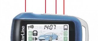
Icon designation
Marking symbols on the communicator display
Description of indicators on the pager screen:
- The option of remote engine start by alarm is activated.
- The remote engine start function using a timer is enabled.
- Remote start mode for internal combustion engines based on air temperature.
- The emergency alarm service function is activated using the Valet button.
- Engine turbo timer option included.
- The automatic activation of the protective function is enabled.
- The immobilizer is turned on - a blocker of the power unit.
- The key lock on your communicator is activated.
- Indicator that determines the temperature of the unit.
- Battery charge symbol in the control panel; if one bar remains, the power source needs to be changed.
- The vehicle's power unit is started.
- Anti-robbery mode activated.
- An additional Starline M20 or M30 satellite module is connected to the security system.
- The luggage compartment of the car is open.
- One or more car door locks are not locked.
- The hood of the vehicle is open.
- The security complex reports that the sensitivity controller is triggered.
- Time.
- The timer for starting the power unit is activated.
- The alarm is on.
- An indicator that determines the presence or absence of communication between the microprocessor unit and the communicator. If several bars are lit near the antenna, then the key fob is within the range of the control module and the antenna.
- If this indicator is not illuminated, the vehicle's door locks are not locked.
- Closed doors.
- The protection option with audible alarms is activated.
- The silent vehicle security function is enabled;
- The alarm indicates that the handbrake lever is not tightened, making it impossible to remotely start the engine. This element can also report when the brake pedal is pressed.
- The indicator signals the programming of a personal password to disable and activate the system. The code may consist of one, two or three characters.
- Engine start mode with manual transmission is selected.
Setting up and programming the key fob
On the alarm control panel you can configure:
- current time;
- alarm;
- countdown timer operating time;
- activating or deactivating the alarm;
- enable or disable the timer.
The procedure for setting parameters is as follows:
- To set the main time clock, click on the third key and hold it. Clamping is carried out until the key fob emits one melodic and short signal, and then two short-term sound pulses.
- The clock indicator on the display will start blinking. Key 1 is used to increase the time display. Button 2 - to decrease.
- Then the third key is briefly clicked. It is used to adjust the minutes of time. Using the first button, the indicators increase, and the second button decreases.
- To set an alarm, you need to briefly click on the key number 3. The indicator on the communicator display will start blinking. The first button increases the alarm clock parameters, and the second button decreases them. To set the minutes, press the third key again. The values are adjusted in the same way - using the first and second buttons.
- To activate or deactivate the alarm, click key 3. While the indicator on the communicator display is blinking, you need to press the first or second button. This will allow you to disable or enable the feature.
- To set the timer, click the third key again. While the option icon on the screen is flashing, the settings are being adjusted. The first button increases the timer values, the second - decreases. To set the minutes, click key 3 again. Use buttons 1 and 2 to adjust the values.
Channel “Crossover 159” clearly showed the procedure for setting the clock on the Starline A91 alarm control key fob.
Preparing to configure autorun
To install a remote start of the internal combustion engine on a car with a manual transmission, the vehicle must first be prepared for this.
The procedure is performed like this:
- You should enable the ignition support option when the power unit is running.
- Then you need to turn on the car's handbrake and remove the key from the lock. If the ignition delay function is not enabled, then between these steps you need to click on the second key on the key fob. The motor will start and should remain running.
- The security system diode indicator will light without interruption or blinking, the side lights of the car will flash once. The signaling control communicator will emit a melodic signal, and the r99 indicator will appear on its display. If the turbo timer mode has been configured in advance, the r01, r02, r03 or r04 icon will appear on the remote control screen.
- Then the driver leaves the car and locks all the door locks. The power unit must remain running.
- On the communicator, click key number 1. The siren will emit one sound pulse, and the side lights of the car will blink once. All door locks should close and the powertrain should stop. If the turbo timer was set in advance, the car’s engine should run for the set time.
- Indicators will appear on the alarm control keychain indicating that the protection mode has been activated. The communicator should emit a short beep. The car's engine is prepared for remote start.
How to enable autorun?
To start the engine remotely, perform the following steps:
- On the main communicator, click the first key and hold it for two seconds, after which the button number 3 is pressed.
- The side lights of the car should blink three times. The car protection system will be turned off, and the sensitivity controller and additional regulator will also be deactivated. The communicator will beep and indicators will appear on its display indicating that the engine is running.
- If you want to extend the operating time of the power unit, you need to press the first button for a long time, and then the third button. The engine will continue to function, and the side lights of the car will blink once. The communicator should play a beep. With each click, the operating time of the power unit increases by five minutes.
- To stop the car's engine, press the second button for a few seconds, and then click the third button. The side lights of the car should blink four times. The communicator will emit a melodic signal.
Autorun by timer
The setup is done like this:
- Keys numbered 3 and 1 are clicked sequentially. The cursor on the communicator display must be set to the position of the fan-shaped icon.
- The desired symbol is selected and the function is activated.
- To confirm, the car's parking lights will blink once. The communicator should play a melodic signal. An indicator in the form of a fan will appear on the key fob display, which indicates that the function has been successfully configured. The alarm status LED will blink in a series of two flashes.
The function can be implemented every:
- 2 hours;
- 3 hours;
- 4 hours;
- 24 hours.
The Stas World channel talked about setting up a remote start of a car’s power unit using the timer function, as well as an alarm clock and temperature.
By time
To configure this option, you need to make sure that the clock on the key fob is set correctly. After this, the alarm clock is programmed for a certain time to start the internal combustion engine, and the function is activated.
Setting option:
- The cursor on the communicator display is set to the position of the clock-shaped indicator. If the function is successfully activated, the vehicle's side lights will blink once.
- The communicator will emit a melodic signal. A clock indicator will appear on the device screen. Along with it, a light bulb in the form of a bell will light up. This indicates successful activation of the option. The alarm status LED will light in a series of two flashes.
By temperature
Activation is done like this:
- The cursor on the remote control screen must be moved to the indicator in the form of a thermometer.
- The function is activated by pressing the first key.
- The vehicle's side lights will blink once. The communicator should emit a melodic signal.
- An icon in the form of a thermometer will appear on the pager screen, this indicates that the option has been successfully enabled. The temperature value at which the security system will attempt to start the internal combustion engine will also be displayed.
Channel “Crossover 159” talked about how to remotely start the power unit of a car in accordance with the air temperature.
Disabling autorun
To safely disable the option, you must take into account the method of remote engine start:
- To disable auto-start on an alarm clock, the cursor on the communicator display moves to the position of the clock-shaped icon. Then the second key fob button is clicked. The car's dimensions will blink twice, and the clock and bell icons will disappear from the device display.
- To turn off autorun by timer, you need to move the cursor on the pager screen to the position of the fan indicator. The second key fob button is clicked once. The communicator will emit a melodic signal, and the car’s dimensions will blink twice.
- To disable the temperature option, the cursor on the screen is set to the indicator position in the form of a thermometer. To confirm turning off the function, click the second key on the communicator. The device will beep once and the vehicle's side lights will blink twice.
How to register a new key fob?
To register a keychain with your own hands, you need:
- Find the Jack key and click on it seven times. If the installation of the anti-theft system was carried out by specialists, you must contact the service center and specify the installation location. As a rule, the button is located in a hidden place - behind or under the glove compartment, under the steering wheel, seat or dashboard, sometimes in a block with safety devices. The engine must not be started when the button is pressed.
- The car's powertrain is then started to bind the new communicator. If the binding process is carried out correctly, the car siren should emit seven sound pulses. This indicates that the microprocessor module has launched the option to add communicators.
- Then on the pager you need to click on the buttons numbered two and three, they are pressed simultaneously. The keys must be locked in the holding position until the car siren emits a sound pulse. This indicates successful binding of the communicator.
- With other devices, the firmware procedure is identical. When the binding of all communicators is completed, the ignition in the car is turned off.
Full use of all functions of the Starline A91 anti-theft system is possible only after flashing a new remote control.
User DimASS spoke in detail about the implementation of the procedure for programming the key fob for the Starline A91 alarm system.
Preparatory actions
Let’s say your car has a “Start/Stop” button and you need to install the car alarm correctly. Only the power cable can be connected to the connector responsible for autostart. True, then the system will protect the car, but will not start the engine. And the last option is not easy to implement:
- It is necessary to determine which pedal (“brake” or “clutch”) is pressed by the car until the engine starts;
- If you need to duplicate the “clutch,” a relay is connected in parallel with the microbutton, which the alarm will control according to its program;
- A separate wire is pulled from the alarm to the microswitch of the brake pedal, that is, to the contact that receives the “12 Volt” potential when pressed;
- The signaling itself in cars with automatic transmission will monitor the brake press, but for manual transmission another option is suitable: the control input is connected to the handbrake limit switch.
By the way, it didn't say how to connect the ignition wiring. It is better to immediately provide the diagrams.
One 18-pin terminal block is connected to the Starline A91 Dialog alarm system, that is, to its X3 connector. It is equipped with a gearbox selection loop, which is broken to install the signaling system on a car with a manual transmission. In the same terminal block there is an “orange-purple” cord. It must be connected according to one of the following schemes:
Connection of “brake control input”
Next, it is advisable to connect the “blue” cord from connector X1 to the relay. It will duplicate the microswitch:
Emulation of a standard pedal micro-button
The two “top” diagrams, by the way, are taken from the Starline basic manual.
Let's assume you know where you need to apply the "+12" potential to emulate pressing the pedal. Then you can install your car alarm without using a relay. Connect the “blue cord” to the required point directly. There is no need to install a blocking diode.
What to do if autorun doesn't work?
Causes and methods of eliminating problems in the event of failures in the operation of the remote start of the internal combustion engine:
- If safe autostart is not possible, there is a possibility that the vehicle does not have a standard immobilizer bypass module installed. The presence of a power unit blocker will not allow starting the internal combustion engine; sometimes the engine starts and immediately turns off. It is unlikely that you will be able to disable immo, so you need to install a bypass module. The manufacturer Starline produces special devices for its anti-theft systems.
- The microprocessor module does not read the tag from the key or communicator. As a result of a malfunction of the transponder, it will not be possible to start the internal combustion engine. There can be many reasons for its malfunction - from software failures to a dead battery in the car. You need to check the battery charge.
- When installing the anti-theft system, the alarm was not connected to the engine control wires. To eliminate this problem, it is necessary to diagnose the correct connection of the electrical circuit elements. It may be necessary to install missing parts.
- A black-gray contact is responsible for autostart on Starline A91 models. It must be connected to a tachometer or generator set indicator. If the electrical circuit is not connected, then when the internal combustion engine starts, the starter mechanism and ignition system will be activated. If the starter cranks poorly, a light will appear on the remote control screen indicating that the power unit is starting, but the engine itself will not start.
- The reason may be poor power supply to the anti-theft installation. A detailed inspection of power lines is required to detect an incorrectly functioning section.
- It is possible that when installing the car alarm, not all wires of the ignition system and starter mechanism were connected. In some vehicles, separate conductors are used to connect these elements and systems, it all depends on the car model.
- The problem may appear after installing the transponder. This is usually due to the fact that the tag installed in the key is not read by the module in the ignition switch. To fix the problem, you will need to increase the number of turns in the coil on the immobilizer bypass unit. You need to make sure that the installation of all elements was carried out correctly.
- The reason may be a dead battery on the remote control. The display of the communicator shows the level of charge of the power source, so if it decreases, the battery must be replaced.
- It is possible that you cannot configure the function as a result of a breakdown or incorrect operation of the communicator due to damage. A failed key fob must be replaced; it must first be programmed. If moisture or dust gets inside the device, it will have to be disassembled and cleaned.
- The malfunction may be due to hardware problems with the key fob. To restore functionality, it is necessary to carry out detailed diagnostics of the device. Often, reflashing the pager can solve problems in its operation.
- If the engine does not automatically start based on temperature, the temperature controller may have been installed incorrectly. You need to make sure that the device is installed correctly and connected to the electrical network. The sensor must be connected to the microprocessor module. Perhaps the controller itself has failed. This problem is more relevant for regulators that have exhausted their service life. A failed sensor must be replaced.
Pinout
To connect all components to the microprocessor module of the anti-theft installation, it is necessary to take into account the pinout of the device:
- The black conductor is ground or ground. It needs to be connected to the car body. You can choose one of the bolts fixed to the vehicle body.
- A short cable loop, made in black, is the transmission. If the car is equipped with an automatic transmission, then this element does not need to be touched. When a car has a manual transmission, the loop must be cut.
- Black-green and yellow-green contacts are required to connect to the turn signal indicator lights.
- The gray conductor is intended for connecting a siren.
- The black and blue contact is used to connect to limit switches on car doors.
- The gray-orange conductor is designed to connect to the limit switch mounted on the hood. The temperature controller of the power unit can be connected to this contact.
- The white-orange conductor is used to connect to the limit switch mounted on the tailgate.
- The pink contact on the microprocessor module is necessary to connect to the negative terminal of the engine blocker bypass. If the car is not equipped with an immobilizer, then this element does not need to be touched.
- The black-gray contact is a line for monitoring the signals of the generator device. Its connection is necessary if the car has a remote engine start option.
- The lilac-orange cable connects to the parking brake lever. This contact must also be connected when using the power unit autostart option.
Six-pin connector pinout
The pinout features of the six-pin connector are discussed using the example of the Starline A91 model:
- The red conductor represents the positive 12-volt terminal. May have a pink tint to connect to the car's central locking system.
- The yellow contact (IGN1) is used to maintain the ignition system. Sold in cars with auto-start internal combustion engines.
- There is no need to touch the blue contact when connecting, it is not used.
- The thick yellow and black conductor goes to the starter assembly. To connect it, you need to cut the red cable of the ignition switch.
- A thin yellow-black conductor goes directly to the lock. To connect, you need to cut the red cable.
- The green contact does not need to be touched, it is not used.
Features of the ignition switch pinout
Connection:
- the blue contact represents the positive twelve-volt output of the microphone of the controller of the installed key;
- black conductor - when the doors are not locked, a negative signal is generated in the system;
- red contact - positive twelve-volt output for connection to the starter device;
- black-blue output - 12-volt contact after activated ignition;
- the green contact provides twelve-volt voltage when the key is installed in the lock;
- white output - a positive pulse of 12 volts for connection to the diode element;
- The pink conductor represents the positive contact coming from the battery.
Connecting the central lock
Pinout features:
- The blue contact must be connected to the white conductor of the central lock;
- the green cable connects to the brown output;
- An activator must be installed on the driver's door.
Pinout of limit switches on doors
Connection:
- the blue and white conductor goes to the driver's door;
- there is a brown contact on the front passenger door lock;
- a black and white conductor goes to the rear passenger door on the left;
- The rear door, installed on the right, has a white-red contact.
Photo gallery
Some connection diagrams can be seen in the photo.
Connection diagram to CAN and LIN buses
Connection map with warning lights and central locking
Connection diagram to car lighting devices
Video “Detailed overview of the functions of the Starline A91 anti-theft system”
The “Crossover 159” channel fully described all the options that can be configured using the communicator from the security system of this model.
Do you have any questions? Specialists and readers of the AUTODVIG website will help you ask a question
Was this article helpful?
Thank you for your opinion!
The article was useful. Please share the information with your friends.
Yes (50.00%)
No (50.00%)
X
Please write what is wrong and leave recommendations on the article
Cancel reply
Rate this article: ( 2 votes, average: 4.50 out of 5)
Discuss the article:
Remote engine start
Available in the following options:
- At a distance by command from the remote control;
- Periodically according to the timer settings;
- By alarm setting time;
- According to ambient temperature.
What steps are taken to set up software neutral?
· The parking brake system is activated. The engine is running.
· The driver leaves the place, closing the doors. The motor continues to run
· By pressing button No. 1, the car is armed.
· The motor is ready for remote start.
Table: starting, extending operation and stopping the engine from the key fob
| Manipulation | Information from the machine | Information from the key fob |
| Start the engine from a distance | ||
| Key No. 1 for a long time, then key No. 3 briefly |
|
|
| Extending the operating period of the motor | ||
| Key No. 1 for a long time, then key No. 3 briefly |
| |
| Stopping the engine from a distance | ||
| Long press key No. 2, then click on No. 3 | Optics gives four flashes |
Table: instructions for setting autorun by time
| Manipulation | Information from the machine | Information from the key fob |
| Setting a timed start | ||
| Long press of button No. 3 | LED flashes in blocks of three | The keychain makes sounds - long and short |
| Button 3 on the remote control is released | — | Icons flickering in the display control bar |
|
|
|
| Disabling start by time | ||
| Two optical flashes |
|
Table: temperature trigger setting
| Manipulation | Information from the machine | Information from the key fob |
| Activation of autostart by temperature | ||
| Key held #3 | The LED blinks in blocks of three flashes | Alerts are sent to the key fob - long and short sound |
| The key is released | — | Flashes on the display |
|
| |
| Shutdown | ||
| Two optical flashes |
|
Table: autostart on alarm clock
| Manipulation | Information from the machine | Information from the key fob |
| Activating autorun by setting an alarm | ||
| Button #3 is held down | The LED blinks in blocks of two flashes | Alerts are sent to the key fob - long and short sound |
| The key is released | — | Blinking on the screen |
|
| |
| Shutdown | ||
| The optics will blink twice. |
|
Supported lock types
Starline e91 alarm system with auto start (key fob operating and installation instructions)
StarLine A91 is equipped with two built-in blocking channels:
- The power relay included in the autostart module is connected to the break in the starter control wire and can only be used to block the starter (a pair of black and yellow wires). In fact, the wire from the ignition switch is used by the central unit as a signal; when the driver turns on the starter, the built-in relay supplies current to the solenoid relay not from the ignition switch, but from the power supply circuit of the alarm unit itself. If the retractor malfunctions, when the current consumption exceeds the calculated one, the fuse protecting this part of the alarm power supply blows and completely de-energizes the autostart control power circuits.
- An additional starter blocking terminal (black and white wire) can be used instead of blocking the starter with a built-in relay; in this case, an additional relay with normally closed contacts cuts into the gap.
- An additional random blocking pin (black and red) can be used to organize any break in the signal or power circuit.
It should be taken into account that in StarLine A91 the algorithm for the functioning of all interlocks is determined by the general setting, so the installer can use relays of only one type - with normally closed or normally open contacts, but without mixing them.
Video: StarLine A91.AVI
The most effective blocking that can be used with the A91 is the installation of wireless relays such as StarLine R2 (not included in the delivery package). Up to two such relays can be stored in the memory of the central unit, installed together with the alarm at the discretion of the master.
Setting comfort modes Starine A91
The main 2 parameters by which autostart is activated are temperature and time indicators. The automatic engine start option is used when preheating the engine in the cold season. The turbo timer mode controls the shutdown of turbocharged engines.
Setting up autostart alarm Starline A91
The StarLine A91 car alarm option under consideration is configured subject to the following conditions: the StarLine A91 alarm package must include a temperature sensor in working condition.
The first option we will consider is setting up the engine to start automatically according to the programmed temperature. The option is activated:
- Long press the 3rd key fob button (marked “*”);
- Over time, single signals (long and short sounds) will appear;
- After releasing button 3, on the screen of the StarLine A91 car alarm key fob, the “icon” indicating the temperature will blink, located at the bottom left;
- After briefly pressing button 3, move the cursor to the thermometer icon. The LED in the car will turn on 3 times.
Having completed the preparation, press button 1 briefly, the required StarLine A91 alarm mode is activated.
The correctness of the actions is confirmed by a short-term one-time activation of the side lights. At the same time, the key fob notifies with signals: 2 short; 1st melodic. The selected option will be marked on the screen with an “icon”, with the temperature value at which the motor will start.
The startup mode is configured: by placing the cursor on the temperature “icon”; by pressing button 2 of the StarLine A91 car alarm key fob. The dimensions will flash 2 times. A melodic sound is heard, the “icon” disappears.
The minimum time when the next autostarts are possible is in the range of 1 hour. There are no restrictions on the number of starts.
Autostart time is configured as follows:
- Press and hold the key fob button “*” (3) for a long time;
- The StarLine A91 alarm key fob gives a short signal, after the next signal appears, the button is released;
- The leftmost “icon” will begin to blink;
- By pressing the “*” button, set the cursor to the “icon” depicting fan blades;
- A short press of button 1 (closed lock symbol) of the key fob causes a melodic sound to appear;
- A ten-second delay is required until the signal appears; the “icon” depicting the fan blades must be darkened.
In the mode – autostart by time, car alarm StarLine A91, activated by button 2 – “open lock”. The car will flash its headlights once, and the key fob will emit a melodic sound. The setup has been made, then the StarLine alarm will issue commands to start the engine at a strictly programmed time.
To turn off the configured startup option, you need to reposition the cursor on the “icon” with fan blades, press button 2 on the key fob - “open lock”. Switching off is signaled by two flashes of side signals, accompanied by a melodic signal from the key fob. The “icon” will disappear.
Setting up the Starline A91 alarm turbo timer
When the StarLine A91 alarm turbo timer is turned on, the hood position is checked. It must be closed. The gear shift knob is set to the neutral position, the motor is in working condition. The sequence of actions is as follows:
- The handbrake is applied.
- The key is removed from the ignition, the driver gets out of the car and closes the existing doors.
- In this case, the StarLine car alarm LED lights up continuously, the side lights blink once.
- The key fob will emit a melody sound, and the “icon” – TURBO – will be marked on the screen. Press button 1.
- The StarLine A91 alarm system will emit 1 signal. The side lights will flash 1 time. The ignition zone and sensors are turned off, the doors are locked, with the locks connected to the StarLine car alarm.
- The key fob emits a short signal. The screen “icons” symbolize the running engine and the security mode.
The turbo timer is programmed as follows:
- Press and hold button 3 of the key fob until 2 beeps sound (long and short).
- Release the button, the first “icon” on the left on the key fob screen is highlighted.
- The cursor moves with button 3 to the TURBO “icon”.
- Press button 1 on the remote control. The side lights will flash 1 time. The key fob will emit signals: short - 2 times; melody – 1. The TURBO “icon” is highlighted; while it is highlighted, the turbo timer option is activated in auto mode.
Disabling the described option is performed in the reverse order, until the TURBO “icon” darkens.
Priora controller connector: how to properly connect the alarm system
Installation of the security system is quite simple and the primary connection points for the Priora alarm system are located on the controller connectors. First of all, connection is made to X1: 12V power supply to the red wire (numbers 2,3), turn signals are connected to the blue and blue with a black stripe wire (pins 14 and 15).
This connection stage is responsible for the normal functioning of the turn signals during alarm installation. And in addition, they will guarantee the correct operation of this part of the car’s electronics.
Next, work is done with connector X2, to which the wires from the ignition and hood will be supplied and connected. To connect the ignition, you will need to connect the orange wire (numbered 9) to the connector. A white wire with a black stripe (pin 17) is connected from the hood. This work is carried out for the following cases:
1. Preventing an attacker from trying to open the hood.
2. Prevent attempts to damage or remove the battery.
3. Normalization of autorun operation.
4. Correct functioning of the protection system.
The next step will be for Priora to connect the connection points on the last X3 connector. The work is quite simple and consists of connecting the wires leading to the limit switches. For the front doors, you will need to connect the brown wire (pin 7) for the passenger door and the blue/black wire (pin 6) for the driver's door to the connector.
Next, connect the yellow wire with a red stripe (pin from the trunk) and the gray wire with a red stripe (pin 1) for the rear doors.
Starline button combinations
Overview of the cenmax alarm (cenmax), operating instructions, reviews
Buttons 1 and 2 in sequence:
Enabling silent security mode.
Buttons 1 and 3 in sequence:
starting the engine or extending the operation of an already running engine.
Button 2, then button 1:
Activating the security mode with the engine running (single presses).
Buttons 2 and 3 in sequence:
Buttons 3 and 1 in sequence:
activation of additional channel No. 1.
Buttons 3 and 2 in sequence:
activation of additional channel No. 2.
Buttons 1 + 2 simultaneously:
- turning on the “panic” mode (long press with the ignition off);
- turning on the anti-robbery mode (long press with the ignition on).
Button 1 + 3 simultaneously:
turning on the key fob button lock (single press).
Buttons 2 + 3 simultaneously:
disabling the key fob button lock (single press).