The Starline A91 security system, equipped with an automatic engine start module, provides reliable protection for vehicles with any type of power unit and transmission. To transmit control commands, an interactive authorization algorithm with a cryptographic code and an individual encryption key is used, which excludes intelligent electronic hacking.
Specifications
The Starline A91 Dialog security complex has the following technical parameters:
- operating frequency of radio control signal transmission - 433.05-434.79 MHz;
- number of independent control channels - 128;
- operating distance of the key fob transmitter - 600 m;
- distance for receiving signals with a key fob (pager functionality) - 1800 m;
- operating range of the additional remote control (with a one-way communication channel) - 15 m;
- temperature range of guaranteed performance - from -40°C to +85°C;
- supply voltage (DC) - 9-18V;
- The shock sensor design is a piezoelectric element;
- Constant current consumption in standby mode is no more than 15 mA.
The operating distances of key fobs declared by the manufacturer were obtained in conditions without radio interference. In dense urban areas, the distance is reduced by 3-6 times.
The control unit of the Starline A91 security complex allows currents of the following strength:
- siren power supply - 2A;
- control of direction indicator circuits (separately on the left and right sides) - 7.5A;
- electric side door lock drive - 15A;
- ignition or starter circuits - 25A each;
- control of additional equipment ACC - 25A;
- power unit operation blocking controllers - 15A;
- additional channels - 0.2A;
- backup engine blocking (external type) - 0.2A.
We are working on bugs
In theory, any car alarm has the properties listed here. The presence or absence of difficulties in setting is determined by the vehicle’s circuitry, and not by the presence of a malfunction in the security system. Starline, however, provided the user with instructions on how to solve the problems that arose. For example, the following effect may be observed: at low temperatures, startup is carried out “every other time,” but in the warm season there are no problems. This means that, most likely, “charge lamp” control is used, and the voltage at the generator output appears too early.
The generator should work like this
It would be pointless to change the sensitivity of the control circuit, and this option is not provided in the Star Line signaling. Use another method, such as tachometer monitoring.
If it is not always possible to set up control by the generator, as well as by the tachometer, then the question arises whether it would be easier to control only the voltage. Skip programming function 11 and get this option right away. And then try the verification procedure. In almost every modern car it will fail.
There is advice that is not given either in the instructions or in the reviews. Having connected the “black-gray” wire to the charge lamp, try using both settings options – 2 or 3. If this does not help, connect to another contact of the lamp. But the best method, as Starline experts themselves say, is to read the engine tachometer signal.
ICE tachometer pulses
To implement this option, the control cord is connected to the high-voltage terminal of the tachometer. You can also use the injector control output if we are talking about an injection internal combustion engine. Then the sensitivity of the signal input is adjusted, and this operation is discussed in more detail in the following chapters.
The functions of more complex systems that do not belong to the Star Line Dialog family include monitoring the operation of the internal combustion engine using an oil pressure sensor. The method works ideally only with some engines, and at low temperatures it malfunctions. Use exactly the control method that is reliable when used under different conditions.
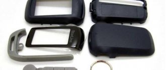
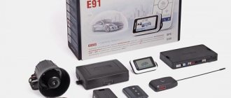
Equipment
The standard car alarm delivery set includes:
- documentation for installation and configuration;
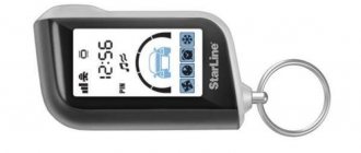
- 2-way communication key fob equipped with a screen;
- AAA size battery for the main remote control;
- protective cover for the main control device;
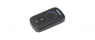
- auxiliary key fob with 1-way operation channel (with pre-installed CR2450 battery);
- central controller of the complex;
- receiver-transmitter equipped with a built-in antenna;
- adhesive tape for installing the antenna unit (2-sided);
- shock sensor with 2 levels of sensitivity (adhesive tape included);
- wiring harnesses for the receiver-transmitter and shock sensor;
- limit switch mounted under the engine compartment cover;
- settings and service button;
- LED element designed to display the operating mode of the signaling system;
- temperature measurement sensor;
- main wiring harness equipped with an 18-pin connection block;
- oversized wiring used to supply power and connect to the ignition and starter circuits;
- wires for connecting with the central locking controller (equipped with a plug with 6 elements).
Photo gallery
General view of the packaging
Arrangement of elements inside the box
Set details
Documentation set
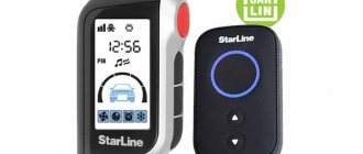
Comparison of the sizes of the key fob and the central unit
Example of installing the unit on a car
Automatic arming
This mode makes it possible to arm the car immediately after turning off the ignition, 10 seconds after closing the doors. The time for automatic activation of the security mode is individually programmed.
If the parking brake is not applied or any door button switch is faulty, automatic arming will not occur!
The StarLine A61 Dialog alarm system belongs to the modern family of anti-theft systems, characterized by a wide range of protective capabilities, especially thanks to the new Dialog signal encryption system. At the same time, Starline A61 autostart is possible only with the help of a third-party module, which is purchased separately.
The central signaling unit is equipped with a fairly powerful processor. At the same time, the system is designed to be suitable for the maximum number of car models. It will fit equally well on a brand new VW and a Niva 4x4.
Key Features
The security alarm has the following main functions:
- protection of openable elements of the car body from unauthorized access;
- vehicle protection using a shock sensor;
- the possibility of additional protection by installing an internal volume sensor (in the cabin);
- sending information signals to the key fob with feedback;
- possibility of operation in additional immobilizer mode;
- connecting the siren after sending signals from the sensors (in security mode);
- ensuring the protection of a car with a running engine;
- automatic start and warm-up of the power unit;
- control of standard central locking;
- searching for a car in the parking lot;
- calling the owner;
- built-in protection against accidental pressing of the control panel keys;
- possibility of installing additional GSM standard modules.
General description of the alarm
Car alarm StarLine A93 with feedback and smart auto engine start. There is protection by an interactive control code with 128-bit encryption keys, which protects against interception of the radio signal by code grabbers. The car alarm works great in urban radio interference conditions.
StarLine A93 is equipped with a shock-resistant key fob with an internal protected antenna. The built-in color LCD display displays the clock, timer, vehicle interior temperature and charge level of the AAA battery used. Operation is ensured in the temperature range from -50 to +85 °C. Communication range is guaranteed at a distance of up to 2000 meters.
How to install it yourself
For self-installation you will need:
- carefully study the documentation for the Starline A91 alarm system;
- know the structure of the car's electrical system;
- have minimal skills in installing electrical devices.
Recommendations for placement and installation
A short guide to placing and switching elements:
- It is recommended to place the central controller inside the car in a hidden cavity that is not exposed to moisture. Usually the unit is installed deep in the instrument panel, attached to a power steel frame using plastic ties or self-tapping screws. You can use 2-sided tape. The fixed unit should not move under the influence of vibration loads that occur during vehicle operation. When installing, you should install the unit with the connector block facing down, which will reduce the risk of condensation drops flowing inside.
- Place the receiver and transmitter housing on the windshield or inside the instrument panel. In this case, it is necessary to ensure that there are no metal body elements at a distance of less than 50 mm from the antenna. The range of operation of the control panels depends on the correct installation of this element. The controller includes a temperature sensor. For the element to operate correctly, it must be located away from heat sources (air conditioning ducts, direct sunlight).
- The standard siren is mounted in the engine compartment in a place isolated from heating or flooding with water. Additional waterproofing is provided by installing the socket of the device downwards. The wiring and siren should be located as far as possible from the bottom of the machine, which will reduce the risk of damage to parts by an intruder.
- The impact sensor is mounted on the body frame. The installation point must provide access to the sensitivity adjustment potentiometer.
- If you plan to use automatic start, then you need to install a second sensor under the hood. To attach an additional sensor, bolts on the crankcase or engine block head or any bracket are used. Installing the unit on the motor housing allows you to more accurately determine the temperature of the unit and ensures timely start-up.
- The control diode must be installed in a visible place on the instrument panel or the trim of the front pillars. Installation in a pre-drilled hole is allowed.
- The service button is located in a hidden place, providing quick access to the node. The part is located under the instrument panel or in the mounting safety block.
- Some vehicles require installation of additional switches under the panels of the hood and (or) trunk lids. The condition for normal operation is a gap between the contacts of at least 3 mm (in the closed state). An incorrectly installed and adjusted “limit switch” leads to false alarms.
- Wiring harnesses are laid at a distance from sources of radio frequency interference, which are elements of the ignition system. At the same time, the absence of contact with moving elements - pedals, climate control rods or gearbox - is checked.
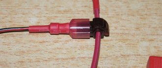
Connection features
When installing and connecting the alarm system, it is necessary to take into account the design features of the car, which affect the settings of the central unit and the connection of wires. The joints must be connected by crimping with a special tube; the use of solder and organic fluxes is allowed. The joint points are protected with insulating tape or heat shrink tubing.
Some installers use wires that imitate the car's standard wiring harnesses for connections. This technique makes it difficult for an attacker to disable the device, but also complicates the further maintenance procedure. When replacing wires, you should take into account the appropriate cross-section, which should not be less than the original one. It is also not recommended to use wiring made of various materials (for example, copper and aluminum).
Step-by-step connection instructions with diagrams
General algorithm for connecting the wires of service elements to the central unit:
- Connect the radio transmitter mounted on the glass using a wire with a 5-pin connector.
- Lay the diode wire. It is installed in a 2-pin block located on the central block.
- Install the service key signal harness equipped with a 2-pin plug.
- Install the wiring for the shock sensor and additional sensor. The -12V signal must be supplied to the additional sensor simultaneously with the appearance of power at the negative output of the central unit. The type of signal processing from this device is programmable.
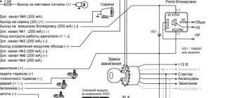
Schematic diagram of connecting elements
Connectors
Connect the wires of the power connector in accordance with the instructions as follows:
- The node with red insulation is supplied with +12V positive power, which comes from the battery terminal. It is allowed to insert the wire into the power circuits going to the ignition switch.
- The yellow wire, responsible for supporting the operation of the ignition system, should be connected to the IGN 15/1 point located on the lock. This section of the circuit is simultaneously used to control the sparking system.
- The existing accessory control output is connected to the ACC connector on the lock. The wire has a green protective coating.
- An additional control output must be connected depending on the programmed operating algorithm. Connection to the brake pedal limit switch is allowed (only if a start-stop button is installed). The wire is equipped with blue insulation.
- The black and yellow wire, which has an increased cross-section, is used to control the activation of the starter. It is connected from the starter side, always after the ignition switch.
- The last wire with black and yellow protection is designed to block the starter when the security is on and to protect against accidental activation when the engine is running.
Connecting the power plug responsible for autostart
A typical connection diagram for an 18-pin central block block is shown in the table:
| Protective coating color | Purpose | Note |
| Black | Negative signal, connects to the car body | There is a separate loop that is responsible for selecting the type of gearbox during autostart. If the car is equipped with an automatic transmission, then the part is preserved; if it is equipped with a manual transmission, it is cut. |
| Green-black | Direction indicators for one side | Load current no more than 7.5A |
| Green-yellow | Likewise for the other side | Identically |
| Grey | Siren control signal (positive pulse) | Allowable current 2A |
| Blue-black | Door lock microswitches connected to ground when opening | — |
| Blue-red | Door switches that provide a +12V signal when unlocked | — |
| Orange-gray | Signal from hood switch closing to negative when opening | — |
| Orange-white | Similar element of the trunk lid | — |
| Yellow-black | The negative output signal of additional channel 1 is used to control the trunk lid lock solenoid. To switch signals, a relay must be installed | The load current is not higher than 0.2A, supplied for 1 second. |
| Yellow-red | A similar element of additional channel 2. Designed to control 2-step opening of locks and control additional modules (via a relay) | It is possible to send an impulse lasting up to 1 minute; it is possible to turn off the signal from the key fob |
| Yellow-white | Identical, used for channel 3, which controls additional equipment | Likewise |
| Blue | Channel 4, used to turn on interior lighting or control the operation of electric window motors | Current up to 200 mA |
| Black and white | A negative signal that determines the state of the security system. It is necessary to control the alarm system, as well as to operate the immobilizer and enable the anti-theft mode. The circuit operates through an unloading relay | Likewise |
| Pink | An additional wire for the complex status, activated at the moment of automatic engine start and when the turbo timer is running. The output can be used to bypass engine locking systems during a remote warm-up cycle | Likewise |
| Black-red | External programmable engine blocking, operated via a contact module. | Likewise |
| Gray-black | Universal monitoring of the operating parameters of the power unit, the input circuit has a resistance of at least 200 kOhm. Connects to tachometer sensor, generator or on-board network (voltage control) | — |
| Orange-violet | Checking the condition of the parking brake lever or pedal. When the negative signal disappears due to the handbrake being released or the pedal being pressed, an alarm will be triggered. When the engine warms up, the operation will additionally stop. | — |
A general view of the wire connection is shown in the diagram:
18-pin connector of the Starline A91 block
Alarm circuits
The alarm circuits are connected as follows:
- To block the engine start, use an additional relay connected to the open circuit. The relay type is selected when setting up the central unit.
- Activate the blocking relay built into the unit by connecting it to the open circuit between the starter and the ignition switch.
- When using an additional radio relay, configure the device individually (write the device code into the alarm memory).
- If it is necessary to use the function of “polite” interior lighting, the unit is connected to a special unloading relay cut to the lighting lamp. The low beam headlights are connected in the same way, which provides a comfortable illumination zone for the driver.
The Starline A91 dialog complex allows operation in conjunction with security and search modules M20 and M30.
Cabin lighting control
Connecting the trunk lid lock drive
Connection diagram for engine blocking with external relay
Activating the built-in start interlock
To the central locking system
The security complex is equipped with built-in relays that allow you to control the standard central locking. The contact groups of the control modules are connected to a block equipped with 6 pins. The circuits and contacts are designed for a maximum current of 15A, while the duration of the control pulse is a programmable parameter.
Possible connection options are shown in the diagrams:
General switching diagram
Connection diagram for 2-wire actuators
Control of pneumatic lock drive system
Connection features for 2-step unlocking of locks
Methods for monitoring the operation of internal combustion engines
Let's say the “black-gray” wire from the main 18-pin connector was connected to the output of the tachometer or to the battery charge lamp:
Autostart options, model A92
Here you see customizable functions responsible for automatic startup. The table is copied from the installation instructions. By the way, don't look for it in the instruction manual.
We will assume that the connection and configuration are completed. Check that the automatic start terminal block (6 wires) is connected according to the instructions. Next you need to disable the security mode to perform the following check:
- The key is moved to the “ignition” mark, the starter is not started, key 3 is pressed on the key fob;
- After starting the engine, press button 3 on the key fob again and monitor the state of the display.
As stated in the instructions, in the first case the display should display the key icon. In the second, an image of smoke is added to it:
Checking engine operation control
The Starline Twage A91 key fob displays the icons shown below.
User manual
According to the operating instructions, in order to make maximum use of the signaling functionality, select a key fob with feedback and an LCD display as the main communicator.
To ensure that commands are written correctly, it is recommended to check the integrity of the battery before programming the remote module. If the key fob indicator blinks, the battery needs to be replaced.
Control key fob
The key fob is a small-sized transceiver module that provides control of the functions of the security complex. Some functions are configured by programming the main controller. The main remote control is equipped with 3 function buttons and a display for displaying various information. The additional device has a simplified design with 2 keys.
The supply of a control signal from any key fob is displayed on the screen of the main remote control, provided that it is within the coverage area.
To select functions on the key fob with a display, a cursor technique is used. Each command has its own icon, which must be selected by moving the “cursor”. Additionally, the screen displays the current time and alarm settings.
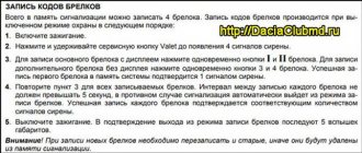
To program a new key fob you need:
- Press the service button 7 times.
- Press buttons 2 and 3 simultaneously and hold them until a confirmation signal is given by the siren and key fob. If a regular remote control is being recorded, then 1 and 2 buttons are pressed.
- Carry out a similar procedure with each key fob (including old ones). The interval between programming should not exceed 5 seconds.
- Pause to complete the procedure. The end of programming will be signaled by a 5-fold flash of the emergency light.
Designation of symbols and buttons on the key fob
The main key fob has 3 buttons and a display, the secondary key fob has only 2 buttons.
General view of Starline A91 control panels
The purpose of the main remote control keys and their combinations is given in the table:
| Button number | Main remote control |
| 1 |
|
| 2 |
|
| 3 |
|
| 1 and 2 | Consecutive presses enable silent mode |
| 1 and 3 | When pressed alternately, the engine autostarts or the operation is extended. |
| 2 and 1 | Single presses provide arming with the engine running |
| 2 and 3 | Stopping the power unit |
| 3 and 1 | Additional channel 1 |
| 3 and 2 | Additional channel 2 |
| 1 and 2 | Simultaneous pressing turns on the panic mode (with the ignition inactive) or anti-robbery mode (with the engine running) |
| 1 and 3 | Safety locking of buttons against accidental pressing |
| 2 and 3 | Removing the key block |
Purpose of the additional remote control keys:
- 1 — arming;
- 2 — disable security or anti-robbery mode.
When performing operations with key fobs, several types of influence on the buttons are allowed:
- short - lasts up to 0.5 seconds;
- long - involves holding the key until a sound signal is given (melody or squeak);
- double - the interval between short impacts is up to 0.5 seconds:
- sequential - can consist of long and short.
The display contains a number of control and control icons:
- turning on and off automatic start by alarm signal (1);
- similarly for timer start (2);
- temperature start (3);
- Valet mode (4);
- turbo timer (5);
- automatic activation of security (6);
- control of the built-in immobilizer of the complex (7);
- key lock indicator (8);
- display of the stored personal access code (9);
- standard security mode (with siren) (10);
- “quiet” security (11);
- locked doors and hoods (12);
- open locks (13);
- ignition activity (14);
- indication of open limit switches on body panels (15);
- The handbrake (16) is not engaged;
- indication of motor operation (17);
- anti-robbery (18);
- battery charge level (19);
- the indicator lights up when displaying the engine temperature (20);
- displaying the connection of additional GSM and GPS modules (21);
- alarm activity (22);
- turning on the timer (23);
- state of the shock sensor and additional sensor, including the receipt of a signal about the activation of the complex (24).
Location of shortcuts on the display
Setup and programming
The control panel equipped with a screen allows you to perform the following operations:
- programming the current time and alarm clock;
- set a countdown timer;
- turn alarms and timers on or off.
To set the current time, alarm clock and timer, the user must:
- Press and hold button 3 until a melodic signal sounds, a short and double normal sound. The hour field will start flashing.
- Use keys 1 or 2 to increase or decrease the value of the numbers. Confirm the value with button 3, which automatically switches the device to programming the current minutes.
- Set the value in the same way and press 3 to go to setting the number of hours the alarm goes off. The algorithm is identical to the procedure outlined above.
- After programming the minutes, it becomes possible to activate or deactivate the alarm. Switching on is carried out by button 1 (the text On will turn on in the field), switching off - 2, text Off.
- By analogy, the timer operation time and its activity are set.
Other functions and special operating modes are set using cursor programming, which is carried out according to the algorithm:
- Enter the setup mode by pressing and holding button 3. Confirmation will be a long and short sound by the buzzer. After this, release the button, the leftmost icon will be selected on the screen (by default).
- By short pressing 3 you can select the required function. To select, press 1, after which the emergency lights are activated, 2 short abrupt signals are given, and then a melody plays. The icon for the selected function remains active on the display.
- Switching off is performed in the same way using button 2.
The owner can program the following services:
- automatic start based on data from the alarm clock;
- start based on timer value;
- warming up based on temperature values;
- service mode used to temporarily disable the complex;
- turbo timer;
- automatic arming 30 seconds after deactivation of the ignition circuits;
- an additional immobilizer that blocks the ability to start the engine 0.5 minutes after the ignition is turned off.
An overview of the functionality of the key fob is shown in the video from the “CrossoveR 159” channel.
Security mode
The complex provides several security modes:
- By pressing button 1, the car reacts with a single light and sound signal, the diode begins to blink. A closed lock icon appears on the key fob screen and a buzzer sounds. When an open limit switch is detected, a 4x light and sound signal is given.
- Double pressing button 1 (long and then briefly) allows you to arm the system without sound confirmation from the siren.
- If you use a long press on 1 and then a short press on 2, the siren is deactivated. If triggered, the vehicle will flash its hazard lights. You can verify that the mode is active by looking at the key fob screen, on which the silent mode sign will be active (speaker crossed out with a cross).
- Automatic arming occurs 10 seconds after the last limit switch is closed. The function is programmed on the key fob and works until disabled through the settings menu.
- The complex allows you to provide security for a vehicle with a running power unit. To do this, you need to set the manual transmission lever to neutral and the automatic transmission to park. After this, the parking brake is applied and the driver opens the door. Switching on is performed by button 2, after which the driver deactivates the ignition, gets out of the car and closes the door behind him. Then you need to press button 1, the security mode will turn on, and the motor will run within the programmed time. After stopping the engine, the security mode is maintained.
Before turning on the security mode, the car owner must check that the doors and hoods are securely closed.
It is allowed to turn on security without a key fob:
- Without turning off the ignition, open the door. The control diode will go into flashing mode.
- Press the service button 3 times. The diode will turn off for 5 seconds.
- Before the diode turns on, the ignition must be deactivated, after which a 1-fold light and noise signal will be given. From this moment the 20-second countdown of the security arming delay starts.
- Leave the car and close the doors using the standard key.
- Wait until the security mode is activated, which is confirmed by the emergency light going off once and the diode switching to flashing mode.
Remote engine start
Before using the remote start, make sure that the hood is securely locked (when installing and using a limit switch). Vehicles equipped with a manual transmission must undergo a so-called “soft neutral” installation procedure. On an automatic transmission, just move the selector to the parking position.
Sequence of steps when starting the engine from the key fob:
- Press button 1 for a long time, and then briefly press button 3. After this, the side lights should light up 3 times, which confirms the temporary disabling of the ignition system protection and deactivation of the shock sensor. The control diode will turn on in constant light mode.
- Wait for the buzzer on the key fob to signal; the display will show disabled zones and warm-up time.
- The starter will crank the engine, a total of 4 starting attempts are allowed. If the motor does not work, the complex will provide feedback to the key fob. The control device will emit 4 beeps and the SP information message will appear on the screen. In this case, the car will give 4 flashes of the emergency lights. If the motor is successfully started, a signal will be sent to the control panel warning about the end of the work cycle. This happens in 60 seconds. before stopping, the inscription R01 appears on the screen, accompanied by 2 series of sound signals (4 short beeps each).
- If desired, the owner can extend the time by repeating the algorithm outlined in paragraph 1. Each button press adds 5 minutes of work.
- To remotely stop, successively press 2 (long) and 3 (short). The buzzer will play a melody and the icons on the display will turn off indicating that the motor is running. The vehicle will respond with 4 flashes of the hazard warning light and the engine will stop.
Automatic start
The security system allows you to start the power unit at a distance according to a pre-programmed algorithm:
- at the certain time;
- repeated restarts after a specified time;
- according to ambient temperature (with repeated heating).
By alarm
The initial stage of programming an alarm start is to check that the current time is set correctly. After this, you need to set the alarm time, which will be used for automatic start. Due to software features, the time difference between the programmed start and the actual start is up to 1 minute.
Sequencing:
- Select the required symbol using the cursor method and activate the service.
- Wait for the emergency light to flash, which is accompanied by a melody from the key fob buzzer. The functional autorun icon and alarm clock icon are activated on the screen. The clock field will display the alarm time for a few seconds. The control diode switches to the operating mode of 2 flashes after a pause.
- After the cycle is completed, the function is disabled. Restarting requires new system programming.
- Disabling the service is carried out using the cursor method, confirmed by double operation of the alarm.
By timer
This function allows you to turn on the power unit after 2, 3 or 4 hours. It is also possible to start daily; the repeat time value is adjusted in the central unit during programming.
Service activation algorithm:
- Select the required function using the cursor method, and then confirm activation.
- Wait for a confirmation signal from the dimensions and the control panel buzzer. Check that the indicator on the display turns on; the control diode should operate in a series of 2 flashes.
- After this, the power unit will automatically start and warm up. Repeated operations will be performed after 2,3 or 4 hours (depending on the parameter programmed on the central unit). Automatic daily repetition of the algorithm is allowed.
To disable the function, use the cursor to deactivate the icon. In this case, a melodious signal is given by the buzzer, the emergency lights are activated 2 times and the control indicator on the display goes out.
By temperature
The temperature-based autostart system ensures that the power unit is turned on at temperatures below the following values:
- -5ºС;
- -10ºС;
- -18ºС;
- -25ºС.
The temperature threshold is set when programming the base unit. The restart control algorithm has a fixed minimum time interval of 1 hour. In this case, the warm-up time is not taken into account. The number of starts is limited only by the battery charge.
In order to configure the function, you must:
- Place the cursor on the icon and activate it. At the same time, the car's hazard warning lights will go off, and at the same time the key fob's buzzer will play a melodic signal.
- The corresponding icon will appear on the screen confirming that the service has been enabled. The clock field will display the trigger temperature.
- The control diode will operate in series of 3 short flashes.
- If you need to disable it, you need to select the icon with the cursor and deactivate it. The control signal is the double operation of the emergency lights and a melodic buzzer signal. The icon on the display turns off and the diode returns to normal operation.
System self-diagnosis
When the security mode is activated, the complex performs self-diagnosis of the following working areas:
- doors and lids of the engine compartment and trunk for complete closure;
- limit switches on moving body elements;
- microswitch of the parking brake indicator.
If problems are detected, the siren will sound 4 times, accompanied by the alarm system. The control panel will emit 4 beeps and the damaged area will be displayed on the display. If the fault is corrected, the complex will automatically connect the zone to the security circuit. In this case, the key fob will give a single signal and the icon that displayed the problem area will go out.
If it is not possible to fix the problem on site, the security system provides protection for the car by bypassing the damaged area. Spontaneous elimination of the breakdown leads to the arming of the zone.
Additional self-diagnosis, carried out when the security is turned off, allows you to obtain information about triggered sensors. When removed, 3 signals are given by a siren and an emergency light; the screen will display the zones that led to the activation of the alarm. If the siren operation was interrupted by pressing the key fob button, then diagnostics are not performed.
The third option for self-test is to determine the number of control panels registered in the memory of the central unit. To do this, press button “3” with the ignition on and count the flashes of the control diode. The number of flashes corresponds to the number of programmed key fobs.
Key lock
The key fob functions provide the ability to block accidental button presses (for example, when worn in a pocket). To do this, you need to simultaneously briefly press buttons 1 and 3. After this, the key fob will give one short signal, and the “KN BLOCK” icon will light up on its screen. The key fob will not respond to all subsequent button presses.
To unlock the StarLine A91 key fob, just press buttons 2 and 3 simultaneously. The key fob will emit sound and vibration signals, and the “KN BLOCK” icon will disappear.
Download installation and operating instructions in PDF format
| Manuals in Russian for operation and installation of alarm systems | |
| Download file: Operating instructions for Starline A91 [6.49 Mb] (downloads: 663) View online file: Operating instructions for Starline A91 | |
| Download file: Installation instructions for Starline A91 [3.6 Mb] (downloads: 562) View online file: Installation instructions for Starline A91 |
What can StarLine A91 do in terms of autostart?
- Random autostart: can be performed at any time when the car is in the area of reliable radio reception or an external GSM module is connected to the alarm system;
- Auto start on alarm clock: the car will start once at the time specified in the alarm clock settings;
- Autostart "Starline A91" using a timer allows the car to independently warm up the engine at intervals of 2,3,4 or 24 hours from the moment the mode is activated;
- You can set the “Starline A91” temperature so that engine warming begins when the engine temperature drops below a specified threshold, but no more than once per hour.
Video: Periodic auto start mode. Car alarm StarLine A91.
Advantages and disadvantages
The advantages of the system include:
- Advanced functionality allowing the owner to select the necessary service or security options.
- Work with signals or in “quiet” mode.
- Automatic engine start allows you to preheat or cool the car interior. The complex is capable of operating on vehicles equipped with a push-button start system for the power unit.
- Transmitted commands are protected by a dialogue code that does not allow the signal to be intercepted and decrypted.
- Customizable key fob with the ability to program additional remote controls.
- An extended set of technical documentation explaining the installation and configuration methods.
- Possibility of expanding the complex with additional sensors and modules.
- Versatility of design.
- Affordable price.
Disadvantages of the security complex:
- Inconvenient temperature intervals during automatic start.
- It is not possible to connect the complex to a digital bus and combine control of standard and additional alarms with one key fob.
- Forced autorun requires manipulation of 2 keys.
- There are problematic components that are replaced under warranty.
- Fragile plastic control key fob. The buttons begin to fall inward over time.
- The alarm system is a budget product. Therefore, the design contains simplified and cheaper components.
Autostart faults
If the Starline A91 autostart does not work, make sure that:
- On cars with a manual transmission, the “soft neutral” procedure was performed, and the car was not disarmed after that (disarming disables the autostart reservation). The handbrake indicator must be lit.
- There is no indication on the key fob screen that the door or hood is open (not closed enough or the limit switch is faulty). Check and correct the problem.
- While near the car, try performing a forced auto start. If the command is not processed at all (the ignition does not turn on), check the connection of the autostart power relays and the condition of the fuses. If the ignition is turned on, the starter operates, but starting does not occur, check the functionality of the immobilizer bypass. If the engine catches, but the alarm turns off the ignition after that, this means that it does not recognize the fact of starting (it does not receive a tacho signal if it is configured for it, or there is no transition in the signal level from the generator when configured to “lamp” - depends on the specific connection and requires inspection by an auto electrician).