The generator on the VAZ 2109 is a device that converts mechanical energy into electrical current. This installation charges the battery and powers all electrical equipment of the car while the engine is running.
Failure of the generator can lead to a failure in the entire vehicle system. At the same time, correct and timely diagnosis will allow you to avoid undesirable consequences.
Next, we will look at what the VAZ 2109 generator is and what is the generator connection diagram. Also in this article we will take a closer look at how the VAZ 2109 generator is checked and how to disassemble the generator if necessary.
Generator VAZ 21099, VAZ 2109, VAZ 2108
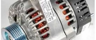
Cars of the VAZ “8, 9, 99” family equipped with a carburetor, fuel injection system (injector) are equipped with generators of type 37.3701, 94.3701.
Both power supplies are AC, three-phase, with pre-installed rectifier and voltage regulator. The rotation side is right.
The first type of power source (hereinafter - IP) is driven by a V-belt, and the second - by a poly V-belt from the crankshaft pulley. Some production models of the “eight” and “nine” are equipped with IP made in Slovenia, marked AAK-5102.
If AAK-5102 fails, it can be completely or partially replaced by 94.3701. The process of self-prevention is not at all complicated, but it requires knowledge and initial experience in vehicle maintenance. Carrying out diagnostics in a non-professional manner does not guarantee the functionality of the equipment.
Lada Priora - generator replacement
The Priora requires a powerful generator; the car has a lot of electronics and a weak installation cannot cope with it.
A generator labeled 5102.3771 is recommended for the Priora, providing a power of 80 A; on luxury versions with even more electronics, a 115 A device is installed. Then which generator is better to install on the Priora?
Car owners recommend a unit produced by KZATEtm Samara plant under number 9402.3701-14, producing 115 A.
There is no need to modify it during installation, you just need to find the connector, because there are differences from the standard one. You can use a plug from a VAZ-2108 from the limit switch for turning on the reversing lights, which costs only 20 rubles.
Next, you will have to make a little modification when connecting to the “B+” power terminal in order to fit it to the desired size.
The cost, of course, of domestic units is higher than that of Chinese or Bulgarian ones, sold for 2200 and 3000, respectively. For Russian ones they ask for about 4000. But if you need repairs with Russian-made components, you can easily find spare parts.
What generator is installed on the VAZ 21099, VAZ 2109, VAZ 2108
| Specifications | 37.3701 | 94.3701 |
| Limit current strength at a voltage of 13.5 V and speeds above 5500 rpm | 56 | 81 |
| Adjustable voltage range | 13,5-14,4 | 13,3-14,6 |
| Gear ratio | 01.01.1970 | 01.01.1970 |
| Capacitor capacity | 2,3±15% | 2,1±15% |
Note to the driver!!! If the IP drive belt breaks along the way, and you don’t have a spare one at hand, cut a 25 mm wide ring from the car inner tube.
To significantly reduce current consumption when the power unit is running, it is necessary to turn off the maximum number of current consumers: radio, radio, lighting, cooler, stove heater.
Generator set price for VAZ 21099, VAZ 2109, VAZ 2108
| Catalog item | Serial number | Price | |
| A2110-80A (original) | BOSCH (9501.3801) (original) | From 3000 – 3200 | |
| 9501.3801 | FINWHALE 687-04 | 62022 / 180545 | From 3000 – 3200 |
| 9568.3749 | 922.3801 | SKL622RS | From 3000 – 3200 |
| 3701010 (HORT) | 3701024 | Contitech | From 3000 – 3200 |
| 3701971 | 3701953 | Electro 3701747 | From 3000 – 3200 |
| *prices are as of August 2022 |
The principle of operation of the power supply VAZ 21099, VAZ 2109, VAZ 2108
There are 6 coils mounted inside the generator set, the material is copper, the connection is star-shaped. The stator is a stationary structure, and the rotor rotates inside the stator. Magnetic brushes are pressed into the back of the rotor axis, and the excitation winding is wound and sealed.
After the key is turned in the ignition switch, the current from the battery creates a magnetic field, passing through the graphite brushes and copper winding. Alternating current is converted to direct current.
On the front side of the IP there are two power outputs with polarity “+” and “-”. Terminals with the appropriate polarity are connected to the battery.
To turn the generator set you will need a battery. After the battery has accumulated the spent amount of energy, the generator distributes the excess to other power sources. Thus, the size of the on-board network is maintained within an acceptable range.
Attention!
Regardless of the model of the VAZ 2109 generator, you must always remember one important rule: the minus of the battery must always be connected to ground, and the plus to the generator terminal. If connected incorrectly, increased voltage will be caused through the valves and they will be damaged.
It is also prohibited to turn on the generator without a battery, as this will cause a short-term overvoltage at the generator output, which will damage the regulator and, as a consequence, cause malfunctions of electronic devices in the vehicle network.
Replacement and repair of generator on VAZ 21099, VAZ 2109, VAZ 2108
Power supply location: engine compartment, to the right in the direction of travel of the vehicle.
Required materials and tools:
- open-end, spanner wrenches;
- knob, heads;
- torque wrench for precise clamping force;
- new drive belt as needed;
- plastic spatula for removing the belt;
- screwdrivers with a set of bits to change the brushes.
Step-by-step replacement instructions:
- We turn off the car engine.
- Open the hood.
- Loosen the terminals and remove them from the battery.
- Loosen the bolt that secures the bracket.
- We bring the generator set down.
- Remove the drive belt.
- We remove the IP from the engine compartment for further prevention.
- Upon completion of the diagnostic work, install the parts in reverse order.
After dismantling the IP, the master cleans it, performs an initial inspection, and determines possible breakdowns. The components are replaced with new ones, the terminals on the rotor are cleaned.
The part cannot be installed if cracks are found in the housing. Subsequent operation of the technical device is unsafe.
We check the integrity of the rotor winding with a multimeter. The diode bridge is also subject to prevention. Do not forget to check the integrity of the fuse, replace it with a new one as necessary, and observe the amperage.
Subject to the recommendations of specialists, subsequent maintenance of the power source after 30 - 40 thousand km.
To extend the life of electrical equipment, follow the technical inspection schedule. Purchase parts with original catalog numbers; a complete list of serial numbers is indicated in the table data.
Contact service station specialists for help if you encounter any difficulties with repairs or maintenance of electrical installations.
Diagnostics of a removed generator
To check the generator removed from the VAZ 21, you should use a multimeter in ohmmeter mode. The probes are pressed against terminal 30 and the body of the unit. If there are contaminants and strong oxides on the case, they should be removed first, as they can affect the readings of the device.
You need to measure the resistance of each generator unit in turn. Parts that do not have the required resistance have become unusable. Most of them can be replaced at home using a minimal set of tools. To replace, you need to buy the same parts as those originally installed in the generator.
Didn't find the information you are looking for? on our forum.
We recommend reading:
VAZ 2110 installation of an electric pump on a car
Where is the oil pressure sensor located on the VAZ 2114 - 8 valves, how to diagnose and replace
Replacing a VAZ generator with a 2110
VAZ 21 12 starter relay where is it located
How to check the thermostat on a VAZ
How to check the VAZ 2114-2115 heater motor, causes of failure and solutions
Throttle assembly VAZ 2110 8 valves
VAZ 2115 check engine light on reasons
Design Features
VAZ 2109 cars can be equipped with two models of generator units. These are 37.3701 and 9402.3701.
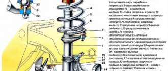
Description of the structural elements of the first:
- 1 — clamping fitting;
- 2 - bushing;
- 3 - buffer fitting;
- 4 — rear cover of the unit;
- 5 - bolt fixing the rectifier device;
- 6 - the rectifier unit itself;
- 7 - valve of this device;
- 8 - capacitor component;
- 9 — rear bearing element of the rotor shaft;
- 10 — slip rings;
- 11 — pulley of the rotor device;
- 12 - brush connected to terminal B of the regulator;
- 13 — contact 30, necessary for connecting energy consumers;
- 14 — contact element 61 of the generating set;
- 15 - brush connected to output Ш on the control mechanism;
- 16 - contact B of this element;
- 17 — the voltage regulator itself in the on-board network;
- 18 — pin for fixing the generating set to the tension bar;
- 19 — impeller;
- 20 - shaft;
- 21 — washers for fixing the bearing device;
- 22 - thrust ring;
- 23 — front bearing element of the rotor device pulley;
- 24 — rotor winding;
- 25 - pole piece of this device;
- 26 - another winding;
- 27 — stator mechanism;
- 28 — front cover of the generator unit.
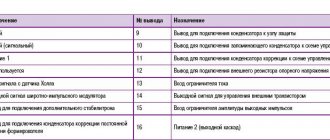
Diagram of device model 37.3701
Design of unit 9402.3701:
- 1 — protective casing of the device;
- 2 — contact B+ for connecting the electrical equipment of the machine;
- 3 - capacitor device;
- 4 - common contact of additional diode elements. It connects to the D+ output on the control fixture;
- 5 — fixing device for positive diodes of the rectifying mechanism;
- 6 — clamp for negative diode elements;
- 7 - positive diode;
- 8 - negative element;
- 9 — voltage regulator in the machine’s electrical network;
- 10 — rear cover of the generating set;
- 11 — coupling bolt;
- 12 — front cover of the generating set;
- 13 - stator winding;
- 14 - thrust ring;
- 15 — front bearing element of the rotor mechanism shaft;
- 16 - shaft;
- 17 - nut;
- 18 — shaft of the rotor mechanism;
- 19 — cone-shaped washer;
- 20 - regular washer;
- 21 — pole pieces of the rotor mechanism;
- 22 — core of the stator device;
- 23 - bushing;
- 24 — winding of the rotor mechanism;
- 25 — rear bearing element of the rotor pulley;
- 26 — bushing of the bearing element;
- 27 — slip rings;
- 28 — brush assembly holder;
- 29 — contacts of the stator mechanism winding;
- 30 - additional diode element;
- 31 - common contact D.
Design of the generator 9402.3701
Carburetor power units are equipped with devices model 37.3701, and injectors - 9402.3701. These units are similar in design; they are synchronous AC motors. They are equipped with a built-in rectifier unit based on silicon diode elements. And the voltage regulator in them is electronic.
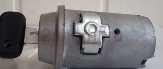
On vehicles built before 1996, 37.3701 models used separate adjusters and brush holders. In such devices, the voltage from pin 30 was supplied to pin B. In later versions, this parameter is supplied to pin B, since B is absent.
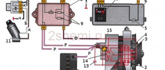
Connection diagram for generator model 37.3701.
When you turn the ignition key, the voltage to turn on the generator is connected to the output through a pilot light and resistors. After the engine is started, voltage is supplied to the field winding from three valves present on the rectifier block. In this case, the control lamp does not light up, since no current passes through it. The main voltage is supplied to the regulator output directly from the generator output.
Since 1996, changes have been made to the model 37.3701 generator, namely, the design of the regulator and brush holder has been changed. From this point on, the voltage regulator is located in a metal case and attached to the brush holder. That is, they have become inseparable.
In addition to the considered generator model on VAZ 2109 cars, you can also see German, Bulgarian and, as mentioned above, Slovenian generators. They can all be replaced with 37.3701. Of course, there are differences, but they are small and related to the design of the generator itself, and in terms of technical data and dimensions they are the same.
- accumulator battery
- generator
- mounting block
- additional resistors 100 Ohm, 2 W
- ignition switch
- ignition relay
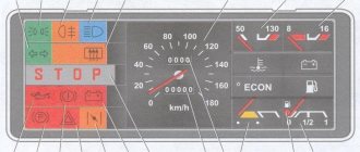
- instrument cluster
- battery discharge warning lamp
How to check for serviceability?
Before diagnosing problems with injection and carburetor cars, you must start the engine and let it run for a few minutes. Then, pressing the gas pedal, you need to increase the number of crankshaft revolutions to 3 thousand/min.
To create a simulation of driving in normal mode, enable:
- driving lights;
- rear window heating systems;
- stoves.
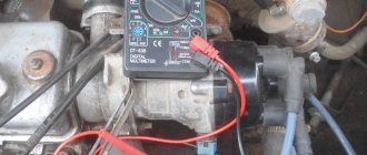
Diagnostics with a multimeter:
- The tester is used to measure the voltage at the battery terminals. This parameter will be 13.2 volts in model 9402.3701 and 13.6 V for 37.3701. If, during diagnostics, without removing the voltage at the battery terminals, the obtained value turns out to be different, this indicates a break or short circuit in the windings of the device. The voltage regulator and brush assembly may also fail. Sometimes the problem is oxidation of the contact components of the field winding.
- To ensure that the regulatory mechanism is working, all energy consumers are switched off. Only the high beam optics remains switched on, after which the voltage measurement procedure is repeated. This parameter should be in the range from 13.2 to 14.7 volts for model 94.3701. In the 37.3701 electric generator, the resulting value will be from 13.6 to 14.6 V.
- If the control element on model 9402.3701 is removed, it can be checked by connecting a light source to the brush mechanism. In particular, between its elements. The lamp should be rated at 1-5 watts and 12 volts. The DC power supply is connected to the D+ pins and device ground. Diagnostics is performed first by activating the voltage at 12 volts, and then at 15-16 V.
- In the first case, the light source should work, but in the second, it should not. If it is activated when 12 and 15 volts are supplied, then a breakdown must be looked for in the regulatory device. If there is no combustion, the cause should be checked for a break or broken contact between the brush elements and the terminals of the device. The regulator itself is changed to restore the generator's functionality. To test the device 37.3701, the light bulb is connected to contacts B and C, this is a plus, as well as to ground.
- Checking the valves of the rectifier device is carried out by disconnecting the cables from the battery, generator unit, and also the regulator contact. The positive terminal from the battery is connected through a light source to the B+ output on the generator device 9402.3701. If this is model 37.3701, then it must be connected to output 30. The negative contact is ground, connected to the housing. If, as a result of the actions performed, the light source started working, then the problem is a short circuit (in both blocks).
- Diagnosis of a similar problem on positive valves is carried out by connecting the positive contact of the battery to the B+ output (for model 37.3701 - contact 30). The connection is made through the light source. The negative contact goes to the output of the phase winding of the stator mechanism (you can connect to any). The inoperability of one or more positive valves will be indicated by activation of the light bulb.
- The procedure for diagnosing a short circuit on the negative contacts of the element is performed by connecting the positive terminal of the battery to the phase winding of the stator mechanism. There should be a light bulb on the electrical circuit, and the negative terminal goes to the housing of the generator set. If the lighting device lights up, this indicates damage to the negative valves or a short circuit of the stator mechanism to the body of the automobile electric generator.
- To prevent short-circuiting of the windings, the assembly is dismantled from the machine, after which the elements are disconnected from the regulator and the rectifier unit. Using a light source or an ohmmeter, parts are checked for short circuits. The valves of the generator device can be diagnosed with a tester; this does not require connecting a battery or a light bulb.
- To check additional diode elements, the positive terminal of the battery is connected to output D through a light source. In model 37.3701, the connection must be made to pin 61. The negative terminal goes to the output of one of the phase windings of the stator device; you can use a screw to secure the rectifier assembly. If the light source lights up, this indicates damage to the diode elements.
- To determine whether the valves are broken, you need to check the output current; this parameter should not fall as a result of the load. But such a problem may be caused by damage or short-circuiting of the windings of the generator unit.
- To diagnose each diode element, you will need a tester or test light. To do this, the rectifier assembly will have to be dismantled. If this device breaks down, it must be replaced as an assembly. It is possible to replace individual valves, but the main elements require re-pressing in the holding device. Performing this operation requires caution and skill from the car owner.
The windings of a stator or rotor mechanism can only be diagnosed using a flaw detector or electronic oscilloscope; the test consists of monitoring voltage curves.
The “Avto-blogger” channel described in detail the procedure for examining a car’s generator unit.
Possible faults
If the node does not work or functions incorrectly, you need to find the cause of the problem:
- When the ignition is activated, the indicator light on the dashboard does not light up. Perhaps this symptom was caused by a faulty fuse. The problem may be damaged wiring. It is necessary to check the electrical circuits and safety devices. Wiring testing is carried out using a tester.
- The LED indicator on the device does not light up, but the battery is discharged, all other control devices are working normally. A possible problem is a short circuit of the diode elements on the bridge or poor contact on the excitation winding. The cause of the problem may be a malfunction of the relay, failure of the brush mechanism, or damage to the wiring from the generator to the dashboard. All failed components can be repaired or replaced yourself.
- The battery indicator light on the dashboard lights up when the engine is running, the battery may be overcharged. It is necessary to diagnose the regulatory device; the problem may lie there.
- When the car engine is running, the battery indicator lights up too brightly or only at 50%. It is necessary to diagnose the drive belt; the problem may be that it is worn out or weakened. To eliminate the malfunction, the belt must be tightened or replaced. The reason may be a short circuit of the stator winding to ground or damage to the electrical circuit. Sometimes the reason lies in faulty diodes or disconnection of the rotor mechanism from the slip rings.
- A whistle comes from under the engine hood. The noise may appear when the power unit is started and disappear after a few minutes, or it can be heard constantly. The problem is due to wear on the drive belt. This product must be replaced.
- A strong hum-like noise may indicate a worn generator set bearing. Sometimes this symptom is associated with a short circuit of the stator winding to ground or a short circuit of one of the diodes.
- At night, when the optics are activated, you can see that the headlights burn dimly. But when you press the gas pedal, their brightness is restored to the required level. The voltage regulator device needs to be checked.
Channel “Tora 18” talked about the main malfunctions typical of automobile generator sets.
Description of the procedure for checking the functionality of the voltage regulator
In the event that a malfunction is nevertheless detected in the specified relay, the vehicle’s maintenance manual clearly describes the procedure for identifying a breakdown. It’s worth noting right away that the main advantage of the 2109 model is the fuel injector. This significantly improves the machine's performance. And the injector is directly connected to a computer, which constantly monitors the quality of work and the condition of the injector itself. If this component fails, then the injector also fails.
The failure in question is accompanied by such problems as:
- increased fuel consumption while reducing vehicle traction;
- dim light from the parking lights, turn signals and instrument panel in the cabin.
If these breakdowns occur, then it is necessary to replace the generator current regulator relay. We will describe the correct procedure for checking the voltage regulator of a VAZ 2109 generator. If you have a car model with the described part installed, then:
- you need to take a voltmeter;
- start the car engine and set the speed to 1500-2000 per minute;
- turn on the low beam headlights;
- measure the voltage at the battery terminals.
In this case, the result of the measurement in the range of 13.5-14.2 Volts is considered normal. If the indicator deviates in one direction or another, we can confidently say that the VAZ 2109 voltage regulator is faulty. The generator voltage regulator cannot be repaired, and it simply needs to be replaced.
But there is another important point that needs to be recalled. You need to make sure that the malfunction of the electrical system lies precisely in the fact that the regulator relay has failed, but not the dashboard warning lamp. This is due to the fact that power is supplied to the excitation winding of the generator from it and, if the lamp burns out, power is no longer supplied to the winding and the generator will not work.
The same diagnostics is possible for the VAZ 2108.
Diagnostics of the functionality of the voltage regulator on a removed generator
Modern industry produces voltage regulators in the same housing with brushes. This makes the design more compact and at the same time more reliable.
To carry out the diagnostic procedure, it is necessary to connect power to the ground terminals from an external power source. Even a pair of one and a half volt batteries can serve as this source. Additionally, a low-power lamp with a power of no more than 3 Watts is connected to the circuit. All links of the chain are connected by wires.
If the lamp does not light up, or lights up when any power is supplied, then this indicates a malfunction of the VAZ 2109 generator relay. If the lamp does not light up at all, then there is a break in the wires of the generator brushes. In both cases, replacement of the damaged circuit assembly is required.
Note that a similar procedure for diagnosing a fault in the VAZ 2109 voltage relay is also used on some other VAZ models. For example, a similar procedure for the VAZ 2108.
Instead of a conclusion
We did not describe the procedure for replacing a generator or regulator relay because in the first case there is separate information with a complete step-by-step description of all actions, and in the second, the procedure is very simple and does not cause difficulties even for novice motorists.
All that remains is to wish fewer car breakdowns and successful, accident-free driving on the highways!
AutoNews / Reviews / Tests
The VAZ 2109 car model began to be produced in the early 90s. Nowadays, this model is significantly different from older releases - it is more comfortable and easy to use. The serviceability of a car depends in almost everything on a constant current power - the voltage regulator and relay are responsible for this.
How to repair it yourself?
The restoration procedure consists of several stages:
- First you need to dismantle the unit.
- Then it is disassembled, at this stage the unit needs to be repaired.
- After this the assembly is performed.
- At the final stage, the node must be installed and connected.
Required Tools
Before completing the task, you need to prepare:
- vice;
- removable tool for bearing devices;
- set of wrenches;
- screwdriver set.
Removing the generator
The dismantling procedure is performed as follows:
- The cables are disconnected from the generator set. They are usually made in red insulation and include 2 groups of conductors. One of them consists of two cables and is fixed with a nut to a bolt on the rear wall of the unit. The second group includes one cable and is connected to the terminal of the generator device via a contact element. It is also located on the back wall of the unit.
- To remove the generator unit from the power unit, you need to unscrew two nuts and a screw. First, the fastening element installed on the drive belt tensioner bar on top of the unit is unscrewed. Then the screw is unscrewed, which secures the part itself to the engine block of the machine, this element is dismantled. At the final stage, the nut is removed from the screw securing the bracket to the internal combustion engine.
- The fixation part is located at the bottom of the power unit, directly under the generator set. After the nut is removed, the drive belt must be removed from the shaft.
- The screw securing the assembly must be pushed to the left so that it comes out of the bracket. The element is pressed all the way into the vehicle body or into the mud shield of the unit.
- Then the two screws located on the right wheel side are unscrewed. They fix the dust protection of the generator set to the car body.
- If the bolt rests on the elements of the machine body, apply a little pressure to the motor. At the same time, the fastening part is removed.
User Sanya Kiselev spoke in detail about the procedure for dismantling the installation from the Nine engine.
Disassembly and repair
After the unit has been removed, all parts are dismantled and the VAZ 2109 generator is restored to functionality:
- Using a 19mm wrench, loosen and unscrew the nut on the rotor pulley. It is used to fix the impeller. To perform this task, the generator unit must be clamped in a vice. Using a screwdriver, the impeller is held from turning. Using a wrench, unscrew the nut counterclockwise.
- The impeller of the device is fixed with a pin. After dismantling it from the pulley, it is necessary to remove this element and put it aside; it cannot be lost. When unscrewing the nuts, it is recommended to sketch the location of the components.
- Then the generator unit is turned over with the back cover up. Using a size 8 wrench, unscrew the four nuts.
- The pins are removed and the front part of the device body is dismantled. The front bearing element is also located here; it is fixed using plates. To dismantle them, you need to unscrew the nuts that secure the elements.
- Using a special puller, the bearing device is removed from the landing site. If you don’t have a tool, you can use a hammer and a mandrel of the appropriate size. The use of a wooden board is allowed.
- The spacer sleeve is removed from the rotor mechanism pulley.
- This unit is removed from the rear cover of the generator device.
- The leads of the stator winding are disconnected from the rectifier. To do this, you need to unscrew the nuts that secure them. After dismantling the fastening elements, the bolts are unscrewed. They record the conclusions themselves.
- Insulating pads are located on the bolts. The stator winding must be removed from the unit housing.
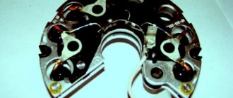
The next step is to remove the diode bridge; this requires the following steps:
- Use a wrench to unscrew the nut that secures contact number 30.
- Next to this pin there is a block with a plug. This element must be dismantled. But you should first release the fastener using a small flat-head screwdriver.
- The latch is disconnected from the inside. Then the block with wires is pushed inside. The plug should remain on the cover. The diode bridge is dismantled from it.
- The next step requires a vice. The rotor mechanism must be clamped into the equipment so that the rear bearing device is located on the top.
- Using a puller, the part is dismantled. To do this, you need to put the tool on top of the assembly and pull the bearing element off the pulley.
Unscrewing the impeller of the generator unit Disconnecting contact 30, connector and dismantling the diode bridge Removing the bearing device from the pulley
After disassembling the elements of the generator unit, replacing the failed components:
- To change bearing parts, you need to check the markings of the elements. Similar spare parts are purchased at the auto store. Even if the bearings are visually intact, it is recommended to replace them. The parts are not interchangeable, so when purchasing, be sure to follow the markings.
- The same goes for the diode bridge. The markings are rewritten from the part, only after that the spare part is purchased. If there is visible damage to this device or metal oxidation has occurred, the unit must be replaced. It is fixed to the generator housing with four nuts. The diode bridge is located at the back, on the inside.
- A visual diagnosis of the front cover of the generating set is carried out. If there are cracks or other damage, the casing must be replaced. When performing visual diagnostics, it is important to pay attention to the fastening elements.
- The diameter of the seat for the bearing parts in the front cover is measured. If the socket for their installation is more than 4.2 cm in diameter, the cover must be replaced.
- Then a visual check is made of the rear of the unit. If there is damage on it in the form of cracks, it must be replaced. Wear or breakage of the seating area under the bearing element is not allowed. If such damage occurs, the cover must be replaced.
- Visual diagnostics of the internal surface of the stator device is carried out. Scratches and other defects resulting from touching the anchor are not allowed. If wear is detected, the bearing elements or the generator set cover are replaced.
The winding of the dismantled rotor mechanism is checked, the task is carried out as follows:
- It is necessary to visually inspect the slip rings. These elements must be replaced if defects are found. We are talking about signs of wear, scuffs, scratches, etc. In principle, the rings do not need to be replaced if the damage is minor. But then they will have to be sanded, for this you will need fine-grained sandpaper.
- If damage to the elements cannot be removed with sandpaper, you can try turning them on a lathe. When using the equipment, it is necessary to remove a minimum layer of metal and then sand the surface.
- Using a tester, the resistance value of the winding of the rotor mechanism is checked. To do this, the device must be connected to slip rings. If the diagnostics show that the resistance tends to infinity, this indicates a break inside the winding. To correct the problem, you will need to replace the rotor mechanism.
- Using a test lamp, a diagnosis is made of the absence of a short circuit in the winding of the anchor device on the housing. To do this, you need to activate the light source by connecting it to the battery. One contact is connected to the body of the anchor device, and the other is connected to each ring in turn. The indicator light should not light up when the rotor is operational. If it is activated, this indicates a short circuit in the winding, then the armature will need to be replaced.
Vyacheslav Lyakhov spoke in detail about performing diagnostics, as well as repairing the unit in the VAZ 2109 car.
Generator assembly
If you managed to disassemble and repair the unit, then after completing the work you will need to put it back together:
- The rear bearing device is installed at the landing site, on the shaft. A wooden board and a hammer are used to complete the task. The bearing is carefully driven in so as not to damage the part. To do this, just hit it several times.
- If the diode bridge was dismantled, it must be reinstalled. The device is located in the back cover of the case.
- The protective casing is then installed on the anchor device so that the bearing element is completely seated. To simplify the action, you can use a hammer. Light blows on the cover clog the bearing; it must be placed on the pulley. The same part installed on the front cover is replaced and fixed using plates.
- Then the generator device is dismantled from the vice. Before installing the front cover on the assembly, the spacer ring is mounted on the pulley. This part should be located between the thrust recess and the front bearing device.
- The cover is installed from the front, the stud nuts are tightened using the crosswise method. This will ensure more uniform tightening of the fastening elements.
- The stud is installed in the recess on the shaft of the anchor device. Then the impeller is installed, the element is clamped with a nut.
- At this point, the assembly procedure for the generator device can be considered complete. All that remains is to install the voltage regulator with brushes at the landing site.
Evgeny Bragin described the assembly procedures for the “nine” unit, indicating all the nuances of this process.
Installation and connection
Installation of the generator unit is carried out in the reverse order; when performing this task, it is important not to forget to connect the wire to the control device:
- A fixation bracket is screwed to the installation. A wrench is used.
- The bracket is then screwed into place with the generator set. When performing this task, you do not need to tighten the nut all the way.
- Self-tapping screws are used to secure the unit's dust protection.
- The drive belt is being installed on the generator set pulley.
- The tensioning element strip is being installed.
- The drive belt is tensioned. When performing this task, it is important that the deflection of the product is about 1-1.5 centimeters. When tightening the belt, it is necessary to tighten the nut on the tensioner bar. Then this element is clamped on the bracket until it stops.
After the installation is completed, you need to connect the terminal blocks to the generator device. When performing the task, you need to make sure that the clamps are disconnected from the battery. There should be a total of three wires connected to the unit. Paired cables are secured with nuts to a stud located on the back cover. A male connector must be installed in a female connector.
Then the terminal clamps are installed on the battery, and the power unit is started. The generator unit supplies the voltage required for full operation of all machine devices.
To be sure that the unit is working properly, you need to use a voltmeter to diagnose the voltage that the unit produces.
Generator set connection diagram
Generator check
It is necessary to check the car generator for the VAZ 2109 to find out the cause of the malfunction:
- If there is extraneous noise in its operation, the bearings of the electric generator shaft are most likely worn out.
- Reduced voltage at the “output” of the electric generator means wear of the brushes (see VAZ 2109: replacing the generator brushes yourself) or low tension of the drive belt
- An increase or decrease in voltage at the “output” may be the consequence of a malfunction of the diode bridge of the electric generator
To perform initial diagnostics of faults, you just need to follow these simple procedures:
- Using a voltmeter, we check the voltage at the battery terminals. When the engine is running and the electric generator is working, the voltage at the battery terminals should range from 13.8 volts to 14.5 volts
- Turn on the engine and place your palm against the body of the electric generator to detect vibration. When the wear of the bearings increases, the vibration that is transmitted to the housing of the electric generator will be easily perceptible, and it is simply impossible to confuse it with other extraneous vibration
- We check the tension of the electric generator belt: with the engine stopped, press the belt with your finger - the deflection under the influence of your finger should not be more than 1 - 1.5 centimeters
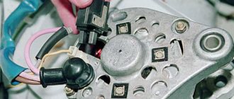
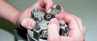
Before removing the electric generator itself, in order to avoid unnecessary and unnecessary work, first remove the relay located on the body of the electric generator with your own hands and check the condition of the brushes and the relay itself in particular:
- Removing the relay does not require removing the generator from the engine
- The relay in the generator is located at the rear, and is attached to it with just two bolts
- To unscrew them you will need a Phillips screwdriver.
- The bolts should be unscrewed carefully, otherwise you will drop their crankcase protection, and getting them out will become an additional problem
- To finally remove the relay you will need to disconnect the wiring with the “female” contact
Checking the relay status
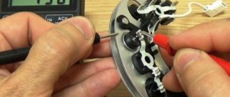
After removal, you must immediately check the functionality of the relay - the voltage regulator, as well as the brush holder and, just in case, the capacitor removed from the generator:
- To carry out the test, you will need a power source with the ability to switch (change the value) of the voltage
- For example, a charger for your battery will do
- A standard voltage test light will also come in handy.
- We connect the control light to the brushes of the relay-regulator
- Then we connect the voltage to 12V, connecting the minus to ground, and the plus to the terminal of the relay - voltage regulator, as in the photo below
- The indicator light should light up
- Now we increase the supplied voltage to 15-16 Volts
- The indicator light should then go out
Such a test will show us if the light did not go out when the voltage increased, or if it even came on in the first case, then replacing the relay on the VAZ 2109 generator with brush holder assembly is inevitable.
Connection diagram for power supply and test lamp to the relay-regulator to check its serviceability
If everything is in order with the relay-regulator, all that remains is to check the condition of the brush holder, to do this:
- It is necessary by pressing your fingers to first check the ease of movement of the brushes themselves in their seats (grooves), and then measure the amount of protrusion of the brushes
- This value must be no less than 5 millimeters
- Marks from various mechanical damages - deep scratches, chips, cracks - are not allowed to appear on the surface of the brushes.
- Brushes with defects, damage, or that do not correspond to the permissible length should be replaced (separately or assembled with the relay, if the price suits you)
Brushes with defects
We complete the test by identifying the condition of the capacitor (if necessary). To check, we need a megohmmeter or a regular multi tester turned on in resistance measurement mode up to 1-10 MegaOhm:
- Turn on the device, which will show the resistance value tending to infinity
- Then connect the leads from the tester to the capacitor, observe at the moment of their connection, the resistance should decrease, and after that the resistance again tends to infinity
- If you observe this phenomenon, know that your capacitor is working properly
- Otherwise, buy a new one and replace it
- Install the generator relay back into the VAZ 2109
This completes the check of the relay-regulator, everything is as simple as shelling pears, just in case, you can familiarize yourself with the video material on this topic.
Safety precautions when working
Nuances that must be taken into account when repairing a VAZ 2109 generator:
- All control and adjustment work related to diagnosing the unit with the engine running must be carried out in a ventilated area or outdoors. If it is a garage, it is recommended to open the doors or provide good ventilation.
- Before carrying out the task, you need to button up your sleeves if the work is performed in a shirt. All hanging ends of clothing should be removed to prevent them from getting caught on the operating pulley.
- To carry out repairs, a specialized tool is used.
- The generator must not be allowed to fall after it has been removed during transportation to the machine. This can lead to complete failure of the unit.
- Repairs should only be carried out using serviceable, clean and oil-free tools.
- If the nuts are rusty and difficult to unscrew, it is recommended to treat the elements with kerosene or WD-40 before turning them out. Dismantling is carried out with preliminary tapping with light blows of a hammer.
- The vehicle is inspected using a 36-volt light bulb. If the diagnosis is performed in a ditch, a 12 V light source will be required. It is important that the light bulb is equipped with a safety net.
Main malfunctions of VAZ generating units
Before you check, without removing, the generator on a VAZ 2115 or another manufacturer's model, you should know that malfunctions of such devices can be electrical and mechanical.
Electrical problems include:
- breakdown of the diode bridge;
- voltage regulator malfunction;
- brush wear, rotor shaft runout;
- winding breakage, puncture (interturn or to the housing).
Features of the VAZ 2108-2115 generator
Mechanical failures include destruction of bearings, damage to the housing, and the drive belt.
Wear, ball bearing wedge
This problem can be recognized by the specific sound of the bearings when the shaft rotates, and the presence of vibration during operation of the electric generator. You can check the performance of the bearings by checking the smoothness of the shaft. If noise is heard during rotation, the ball bearings must be replaced.
Damage to the windings of the generating unit
This fault often occurs at the junction of the ends of the winding with the slip rings. Also, sometimes the winding short-circuits (when the conductor branches off, gaps form). If such damage occurs, the battery stops charging. To diagnose a breakdown you need:
- disconnect the end of the winding from the brush;
- connect the battery wiring to the disconnected end and the terminal of the generating unit through a voltmeter or lamp;
- if the light does not light up and the meter needle remains in place, we can confidently say that there is a break.
In this way, you can check the operation of the generator on a VAZ 2110 without removing it. This method is also suitable for most other VAZ models. To fix the problem, acid-free soldering and soft solder are used. If damage occurs inside the coil, the rotor or starter is replaced.
Signs of wear on generator brushes
Diagnosis of this breakdown is possible without dismantling the generating unit. If you use an electric generator with worn brushes, this will lead to complete failure of the device. Signs of problems with brushes include:
- frequent blinking, dim headlights;
- slow battery charging;
- random switching off of the radio.
Such a breakdown is dangerous because during car maintenance small parts are often not given due attention. Therefore, the problem of worn brushes often takes motorists by surprise.
The malfunction is eliminated by replacing the unit.
Rectifier unit malfunction
A problem may be indicated by rapid battery drain. In this case, you can check the generator on the car for functionality (for VAZ 2110 and other cars of the same brand).
Most often, problems begin after the element overheats, power surges, or mechanical damage. As a rule, failure is associated with breakdown of diodes. This causes a short circuit of the contacts of the stator winding, which leads to the generator becoming unusable.
Problems with the voltage regulator
A malfunction often occurs on VAZ 2114 vehicles. With such a malfunction, problems with the battery begin. The breakdown can also be diagnosed using a multimeter.
Repair of generator VAZ 2108-2115
The generator on a VAZ 2114 car should produce a voltage of about 13...14 V (with the internal combustion engine running). If the device begins to produce a lower or higher value, this will lead to a decrease in battery life. At high voltage (more than 14.5 V), the relay should turn off. If the regulator does not turn off, this indicates a breakdown. This problem can be caused by:
- short circuit in the circuit;
- incorrect connection to the battery;
- penetration of moisture into the housing.
The voltage regulator can also become unusable if the car's electric generator is not regularly maintained.
Repair costs
The approximate cost of spare parts is shown in the table.
| Name | Price, rub |
| Price of a set of bearing elements | Around 150 rubles. |
| Generator diode bridge | 200 rub. |
| Charging relay | About 150-200 rub. |
| Removal tool for bearing elements | Around 100-200 rubles. |
| Prices are relevant for three regions: Moscow, Chelyabinsk, Krasnodar. | |