About the most important thing! The ignition system in cars of the Samara family is non-contact, and it consists of:
Ignition distributor, also known as distributor:
1. First, let's look at what is included in the main composition of the distributor. Firstly, it includes a hall sensor, and secondly, a centrifugal and vacuum ignition timing regulator, and much more.
3. The ignition distributor is needed to perform two main functions:
- The first function it performs is to set the moment of spark formation, which is carried out depending on the car’s engine speed.
- Its next function is that at the right moment it gives a high voltage pulse, in other words, a spark into the cylinders, depending on the order of their operation.
Note! The ignition distributor supplies a spark to the cylinder using a slider that is installed in the distributor itself, and it is put on the distributor shaft there!
Spark plug:
1. Many people already know why there are spark plugs in a car, but let’s take a closer look.
2. Every gasoline car needs spark plugs, and their job is that with their help, fuel particles in the cylinders burn out in a timely manner, due to the fact that the spark plug gives a spark at the right moment, but where does the spark come from for this spark plug? Yes, everything comes from the same ignition coil, with whose help the car’s engine runs.
3. Spark plugs in cars of the Samara family are used according to the type “A17DVR” as well as “A17DVRM” and “A17DVRM1”. There are other foreign analogues, but these are essentially the most common spark plugs used in these cars.
4. Sometimes there comes a time when the spark plugs, so to speak, become obsolete, and therefore they need to be periodically every 30,000 km. replace with new ones. If you still have to replace them, then we have prepared an article for you in which you will find detailed instructions on how to replace them. (see Replacing spark plugs)
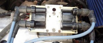
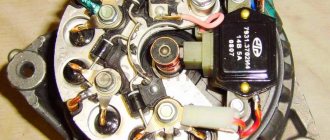
Ignition coil:
1. The coil, as it is popularly called, performs the function of converting a low voltage current into a high voltage current, below we will analyze all this in detail.
2. First, understand once and for all that the ignition coil is essentially an element that works due to the battery, and several other factors. The principle of operation of the coil is as follows:
- First, current is supplied to the coil from the battery.
- After the coil has received current, it converts it into high voltage current, the voltage of which reaches about 25,000 - 35,000 volts.
- Then, after converting the high voltage current, it directs this current to the spark plugs, through the high voltage wires.
- And after the spark plugs have received current, they then use it to produce a spark when the piston approaches top dead center (TDC).
Switch:
1. It is a kind of small module, due to which the following is carried out:
- Current stabilization, that is, in other words, the switch prevents the current from falling below “6 Volts”, and it also prevents the conversion of current above “18 Volts”. Thanks to these actions, the wires of the contactless ignition system burn out much less often.
- It also creates current pulses in the ignition coil.
- It also protects parts from overheating and overload, so they will last a longer life.
- And in addition to all this, the switch de-energizes the ignition in the car at the moment when you turn off the car engine.
2. On cars of the Samara family, switches of the type “3620.3734”, as well as “76.3734” are installed; switches of the type “RT1903” and “PZE4022” are also subject to installation.
3. If the switch fails, it cannot be repaired. If you begin to notice that the switch is becoming unusable, it is recommended to replace it with a new one.
4. It is forbidden to disconnect the block of wires that is connected to the switch when the car’s ignition is on, because this can damage it, and damage to other parts of the ignition system may also occur.
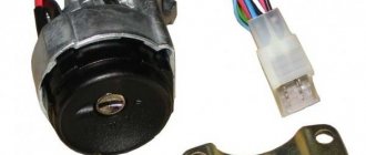
Ignition switch:
1. The switch is a lock, which you have all already seen in every car. Thanks to this switch, you can turn on and off the ignition system devices.
2. The switch includes an individually selected key with which we can turn this switch. And in the switch body there is a fixed disk with terminals and contacts, and the wires that come from the ignition coil are connected to this disk.
3. When the key is removed from the lock, all contacts subsequently open. And when the key is inserted into the cylinder and then turned, in this case all contacts are closed, and therefore the ignition in the car is turned on.
Low and high voltage wires:
High voltage wires:
1. High-voltage wires serve to transmit high-voltage current from the ignition coil itself and to each cylinder spark plug.
2. Cars of the Samara family are equipped with high-voltage wires with a distributed resistance of 2550±270 Ohm/m.
3. Under no circumstances try to start a car with a broken high-voltage voltage circuit, that is, to put it simply: The car’s engine does not need to be started with the high-voltage wires removed, as well as with the ignition distributor cap removed. Such actions can lead to failure of the ignition system elements, as well as breakdown of the insulation, so be careful.
4. It is also not recommended to handle or touch high voltage wires when the car engine is in working condition, because this can lead to electrical injury.
Note! When checking high-voltage wires for the presence of a spark, it is recommended to disconnect the wires with the engine turned off, and if the engine is started, the wires should be secured at a distance of 5-10 mm from the mass of the car, and these wires should not be in your hands, even in only if you hold them with a tool!
Low voltage wires:
1. Every person has encountered such wires in his life; they are most often of small thickness and have a very flexible shape, unlike high-voltage wires.
2. And most often, low-voltage wires have a combined color, that is, they come in both red and blue, and have many other colors.
3. A striking example of where the low voltage wires are connected is the same ignition coil, because if you look at it carefully, then on its side you can see two wires, one of which is “red” and the other “blue”. (see photo above)
This is interesting: Why Vesta turned out to be more popular than X-Ray: comparative analysis
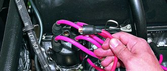
High voltage wires
Often, the main difficulty when repairing a carburetor VAZ 2109 is the reconnection of high-voltage wires that were previously disconnected from the distributor cover. It's also an ignition distributor.
The difficulty is that many people forget the connection procedure or simply do not know. But in practice, returning high-voltage wires is much easier than understanding the ignition module used on the injection VAZ 2109.
By following a few simple rules, you can easily return the wires to their rightful places.
- The ignition distributor cover is installed in its place, that is, on the distributor, only in a single position. Therefore, even if you wanted to, you won’t be able to confuse anything here. Otherwise the lid simply won't fit.
- There is an installation mark on the cover, which indicates the location of the wire socket from the first cylinder.
- The wires must be connected in the following sequence - 1, 3, 4, 2. Move counterclockwise when looking at the distributor cover from the side of the expansion tank.
If for some reason there are no installation marks on the VAZ 2109 carburetor distributor cover, just follow the connection principle shown in the image.
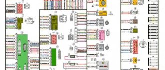
Ignition circuit for VAZ 2109
Every owner of the VAZ 2109 should know the ignition circuit Without knowing this circuit, you will not be able to start the car in case of ignition problems. Moreover, this scheme is elementary simple. The VAZ 2109 is equipped with a contactless ignition system. It consists of the following components: switch, ignition coil, distributor, Hall sensor, high-voltage wires and spark plugs. The task of the ignition system is to provide a timely, cyclic spark to the engine cylinders. Let's take a closer look at how the clamping circuit works.
Ignition circuit for VAZ 2109
ignition of the VAZ 2109: power is supplied to the ignition system through a relay. Until the key is in the ignition position, the relay will not turn on and supply power to the circuit. As soon as the key is turned, the ignition system is energized. +12V power from the battery is supplied to contact B of the ignition coil, the 4th contact of the switch. The Hall sensor powers the switch itself. Please note that the ignition relay is powered through the mounting block, and if there is poor contact in connectors Ш1, Ш8 or for some reason the track oxidizes or burns out, the ignition system will not be powered and the VAZ 2109 will not start. In order for a spark to begin to form, you need to crank the engine crankshaft. Together with it, the camshaft will turn and the Hall sensor will send an impulse to the switch. The commutator, in turn, will connect contact K of the ignition coil to ground, resulting in a spark appearing on the central wire. When the distributor slider connects the central wire and the wire leading to a specific engine cylinder, a spark will jump on the spark plug, igniting the combustible mixture. The engine will start. When it is necessary to turn off the engine, the driver, by turning the key in the ignition switch, turns off the relay, which in turn disassembles the power supply to the system. The switch and ignition coil become de-energized and stop working. The most common malfunctions of the VAZ 2109 ignition system: 1) Failure of the switch. 2) Failure of the Hall sensor. 3) Poor contact of the slider in the distributor. 4) Lack of power supply to the ignition system of the VAZ 2109. Go to Home.
Examination
If you notice signs of a problem with the ignition coil, or have to deal with a situation where the engine “died,” be sure to check the condition of this element.
As you test, you will be able to determine what caused the coil to fail and how the problems can be corrected.
https://youtube.com/watch?v=Z5cUQhKBZm0
How to check the device? The instructions are not complicated, even a beginner can handle it.
First, let's check the condition of the unit, and then check for correctness of the resistance of the coil itself.
- If the engine cannot be started, make sure that the coil itself is producing a spark at all. To do this, the central wire is removed from the distributor and a spare spark plug is connected to it.
- Now take the spark plug with pliers and place the metal casing on the breaker or motor.
- If a spark does not appear when the engine starter is turned, there is a malfunction in the ignition system.
- So check the power to the coil, or rather its presence. For this you will need a multimeter. One terminal is connected to contact B on the coil, and the second goes to ground. Turn on the ignition. If there is no voltage, the culprit is the ignition switch.
- You can start the engine in emergency mode. To do this, the plus from the battery is thrown onto contact B of the coil.
If there is voltage but there is no spark, check whether the primary winding is intact. To do this, the side low-voltage wires are disconnected from the coil and resistance measurements are taken with a multimeter. Then the secondary winding is checked.
Similar articles
How to check the serviceability of the ignition coil
We will tell you about this procedure in more detail.
Multimeter for testing
Checking coil resistance
- Unplug your car. To do this, simply disconnect the negative terminal from the battery.
- Disconnect all wires and leads going to and from the coil.
- Be sure to arm yourself with the necessary tools and a tester. A universal multimeter or ohmmeter will work fine.
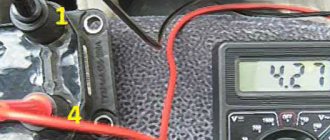
- Take measurements on the primary winding. To do this, the tester probes must be connected to the low-voltage terminals located at the edges of the coil. Before doing this, do not forget to clean the terminals from accumulated dirt and traces of oxidation. Surely they formed during the operation of the car.
- Record the data.
- Now the resistance of the secondary winding is checked. To do this, you need to transfer one ohmmeter probe to terminal B of the coil, and the second to the high voltage.
- Note your results.
- The last stage of the test involves measuring the insulation resistance to ground. To do this, you need to connect one terminal of your tester to ground (this is the ignition coil housing), and connect the second one in turn to all three terminals - a pair of low-voltage terminals and one high-voltage one located in the middle of the device. If the coil is working properly, then in all three measurement cases you will get a resistance of at least 50 ohms.
- Check the table against the previously recorded data.
[media= https://www.youtube.com/watch?v=2F4BDExybgs]
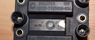
| Coil type | Winding | Resistance indicators |
| 3122.3705 | Primary winding | 0.43 ohms +/- 0.04 ohms |
| 8352.12 | 0.42 ohm +/- 0.05 ohm | |
| 3122.3705 | Secondary winding | 4.08 ohms +/- 0.40 ohms |
| 8352.12 | 5.00 ohms +/- 1.00 ohms |
Repair
In fact, the only way to repair a faulty ignition coil on a carburetor or injection VAZ 2109 is to replace the device.
Here you just need to choose which element will replace your old coil.
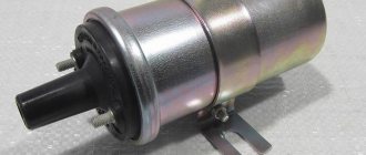
- MZATE-2. This is a standard coil, which all VAZ 2109s were equipped with from the factory. It costs about 600 rubles and serves well;
- An excellent alternative option, characterized by reliability, durability and operational efficiency. But it costs about 1800-2000 rubles;
- Valeo. Something between the factory and Bosch version, which has good characteristics and positive reviews. Today such a reel costs an average of 1,500 rubles.
The coil is the most important element of the ignition system; if it fails, you can forget about traveling about your business.
Loading …
Lada 2109 › Logbook › Dual-circuit ignition on the VAZ 2109
I suffered several times in the winter with starting the engine. Even when it’s not cold, but at 0 degrees, you come to start it and the car is silent. You unscrew the damp spark plugs and the battery eventually dies! With a good battery, it starts normally. As it turned out in the end, I had a contact ignition coil B- 117 from the classics. I immediately changed it to a coil from BSZ. And the car started to start and drive much better, but I didn’t stop there and decided to make a dual-circuit ignition with 2 hall sensors, 2 switches and 2 coils from the Volga ZMZ- 406
To begin with, I began to assemble the distributor because it is the most basic and subtle part of the system. I took the distributor from OKI as a basis, or an ordinary nine-wheel one. I just had it from the window and was lying in the garage. I completely disassembled it and started installing the 2nd hall sensor directly on the standard platform at an angle of 90 degrees. I marked out the approximate position of the 2nd sensor There are risks at the site regarding the approximate position of the middle of the sensor:
Drilled and tapped the threads for the bolts:
Then I carefully cut the hall sensors themselves with a metal cloth so that they do not interfere with each other. It looks something like this:
Then I modified the shaft, replaced the ignition angle advance weights with nine-shaft ones. They are smaller and lighter than those of the Oka, the photo shows Okushinsky weights! And accordingly, I also replaced the springs. The curtain remained the standard Okushenskaya one, I didn’t touch it. If you make it from a nine-shaft shaft, then you need a curtain too modify it by sawing off two opposite ones so that it looks like in the photo:
That's all for the shaft! Next, I cut out a small piece from the distributor body itself to attach the fork of the 2nd hall sensor, drilled a hole and cut a thread for the bolt
Then I put the whole thing together. Here’s what happened:
Note: during assembly it turned out that the platform on which the hall sensors from the Oka are attached is larger than from the 2109 and it turned out to be easier to mount the sensor, so another one +, It is advisable to buy the same sensors themselves in the same store from the same batch as they are slightly different! That's all for now with the distributor!
Then I bought the rest of the necessary parts: 2 coils from the Volga ZMZ-406, a wiring harness for the BSZ 2108, an “Astro” switch, as I already had the same one
I connected the wiring according to the diagram:
Note: when connecting according to scheme 1, the tachometer will show half the revolutions. If you want to make a normal tachometer, then there is also scheme 2, there you will need to solder 2 KD213A diodes. But I did not do this and did it according to scheme 1. And don’t try to connect wires without diodes according to scheme 2, as you parallel both coils and it turns out that all 4 spark plugs spark simultaneously when both hall sensors are triggered! Tested personally)
I made a metal mount for the coils, but it didn’t turn out very well:
And now about the most important thing: for the system to work well, you need to adjust the synchronization of the hall sensors so that the spark on all cylinders is the same advance. To do this, you need to make the opposite mark on the flywheel, this will be the TDC of the 2nd cylinder. You need to count 64 teeth along the crown from the standard mark .And using a strobe light, combine both marks from the 1st and 2nd cylinders, moving the 2nd hall sensor up and down or both sensors in the direction of the white arrows. To do this, I drilled holes with a thin drill in the sensors to move them.
Ignition coil malfunctions
The efficiency and reliability of the entire internal combustion engine depends on how the ignition coil works. That is why regularly checking and taking care of this part of the car is a priority task for any motorist. Problems with the coil can be identified by the following symptoms:
The engine is unstable (especially at high humidity);
Fuel consumption increases;
Engine power decreases;
Jerks and dips occur (especially when you press the gas pedal sharply).
If the ignition coil fails, you will see a fairly obvious sign - the car simply will not start after turning the key. However, to make sure that the problem is in the coil, you should pay special attention to a number of signs.
The most obvious problem is that there will be no spark at the spark plugs;
There is no voltage on the BB wires;
There is smoke coming from under the hood;
The metal on the reel body cracked, a large chip appeared, etc.;
Traces of melted liquid are visible on the coil (this happens if the winding burns out).
As a rule, the coil breaks due to low-quality spark plugs, engine overheating, or damage to some parts in the coil itself (for example, the rubber tip). However, there can be many reasons, and only an experienced technician can determine the exact cause of the breakdown. But the beauty of ignition coils is that any of these problems can be solved by simply replacing the coil. In our store you can easily buy an ignition coil.
Today we will look at the design and diagrams of ignition systems for VAZ cars of all major models. Since carburetor versions of VAZ are practically history, we will dwell in detail on the ignition systems of injection cars. Their ignition system is based on an electronic ignition module. We also recommend that you carefully consider the choice of spark plugs and the quality of high-voltage wires, because the quality of the spark and, accordingly, the operation of the ignition system as a whole will depend on them. The information is intended as a reference guide for self-repairing a car.
Diagram of the ignition system for VAZ 2108, 2109, 21099 cars
Diagram of the contactless ignition system for VAZ 2108, 2109, 21099 cars
Elements of the ignition system for VAZ 2108, 2109, 21099 cars
- Accumulator battery.
Provides electrical current when starting the engine.
Provides electric current when the car engine is running. In particular, it powers the ignition system.
- Fuse and relay mounting block.
Serves for switching low voltage wires, in particular the ignition system.
- Ignition coil.
Provides high voltage current to the ignition distributor.
Provides a pulse for sparking (opening the power circuit of the primary winding of the ignition coil) in one or another cylinder according to a signal from the Hall sensor.
Generates a control pulse (reducing voltage) for the switch, signaling the need for sparking in one or another engine cylinder.
- Ignition distributor (distributor) with vacuum and centrifugal ignition timing regulators.
Serves to generate a control pulse to the switch (Hall sensor), distribute high voltage pulses across the spark plugs (“slider”), correct the ignition timing in accordance with the engine operating mode (centrifugal and vacuum regulators).
- High-voltage wires (armored wires).
They serve to transmit high voltage current from the ignition coil to the distributor cover and then to the spark plugs.
- Egnition lock.
Serves to close the ignition system circuit. Through it, electric current flows into the ignition system.
- Ignition relay.
This is interesting: What happens if the airbag goes off a moment later?
Serves to relieve the contacts of the ignition switch (lock) and supply voltage to the coil and switch.
- Spark plug.
Serve to generate a spark in the engine cylinders.
Notes and additions
More articles on the ignition system
Checking the operation of the circuit
If signs indicating a malfunction of the Hall sensor appear, it is checked without removing it from the distributor. There are several ways to do this:
- 1. To check, you need to have a voltmeter and several pins. The check is carried out in the following order:
- pierce the insulation of the green and black and white wires going to the sensor connector with pins;
- connect the pins to the voltmeter using connecting wires with clamps;
- turn on the ignition;
- slowly turn the engine crankshaft. To do this, you need to rotate the flywheel through the hatch in the clutch housing;
- monitor the readings of the measuring device. If the sensor is working properly, then the voltage on the voltmeter periodically disappears almost completely (0.4 V), and then changes to 9...12 V. Otherwise, it must be replaced.
Diagnostics of BSZ
- 2. In the absence of a voltmeter, the test can be carried out in the following way:
- disconnect the central high-voltage wire from the distributor cover;
- secure this wire so that its tip is located at a distance of 5...10 mm from the main brake cylinder;
- Using a piece of any wire, connect the central contact of the high-voltage wire to the negative terminal of the car battery. If a spark “jumps” between the central wire and the brake cylinder, it means the sensor is faulty and must be replaced.
Features of the operation of different ignition systems
Ignition on the VAZ 2109 is necessary to ignite the air-fuel mixture when starting the engine. If the ignition does not work correctly, the engine will start and run intermittently, and its power during start-up and acceleration will noticeably decrease. In addition, fuel consumption will be noticeably increased. The conclusion from this is that the correct operation of the ignition system should be constantly monitored.
It’s worth mentioning right away the differences in the ignition design of “nines” with different types of fuel supply. Their SZ is similar, but they differ in the elements of electric charge distribution.
- In “nines” equipped with a carburetor, there is a coil and a distributor.
- For systems with an injector, an ignition distribution module consisting of several coils and an electronic controller is installed.
The second difference is how the system works. In cars with an injector it is not required, but in VAZs with a carburetor you have to do it manually.
In nines, two types of ignition systems are used:
- contact;
- contactless with transistors.
The first is installed in carburetor “nines”, and the second in injection ones. Thanks to the use of contactless ignition, the system has the following advantages:
- Working with a Hall sensor, which makes the system more stable and increases its overall efficiency.
- The absence of contact with the working parts and elements of the system increases the service life of the elements and makes maintenance of the circuit components easier.
- Excellent spark distribution between spark plugs.
- Generating a powerful spark, which prevents system failures.
- Fuel economy.
- Works even with low battery charge.
Over time, the contact type SZ has practically ceased to be used, so from now on we will focus on the contactless analogue.
Main advantages
The ignition system used for nines has good reliability indicators, although it produces energy up to 50 kJ, and the breakdown voltage can sometimes reach 30 kV or more. BSZ is valued for its high efficiency.
There are several main advantages that characterize contactless ignition systems.
| Advantages | Peculiarities |
| SZ works with a Hall sensor | Because of this, the spark energy parameters are not affected by the voltage in the electrical network or the frequency of the engine. This is due to the fact that the time period of energy concentration in the ignition coil is always constant. This ensures high efficiency of the circuit |
| There is no mechanical interaction between contacts | This ensures there is no contamination or burning of contacts, so there is no need to clean them |
| No need to adjust the position of the contacts | This can be explained simply - they are not in the SZ VAZ 2109 |
| Minimal mechanical interactions between parts | This factor contributes to the absence of rotor vibrations, resonance, and uneven spark distribution across the spark plugs |
| The energy in the candles is constantly increased | It can reach 50 J, which allows you to avoid failures when igniting the air-fuel mixture in the cylinders. This is especially noticeable when accelerating a car. |
| Cost-effective and environmentally friendly | The use of the new SZ made it possible to improve fuel economy by approximately 5 percent, as well as reduce CO emissions by 20 percent |
| Stable cold engine start | Even if the battery is discharged to 6V, you can still start the engine without problems. This makes BSZ significantly different from other ignition systems that cannot boast of such stability. |
Scheme
How does the scheme work?
The contactless ignition system of the VAZ 2109 has a fairly simple operating principle, based on the sequential inclusion of various elements in the design. The electronic components of the circuit regulate the formation and supply of sparks to the working bodies. All this works according to the following principle:
- The rotation of the starter drives the camshaft, which in turn starts the distributor.
- The distributor contains a Hall sensor, near which there is a device with a hole. It serves to create a signal under the influence of a magnetic field.
- The electrical signal from the distributor goes to the switch.
- From the commutator, energy is supplied to a coil of two windings. There is a multiple increase in the charge, after which it goes to the ignition distributor.
- The current is distributed through the spark plugs, and the air-fuel mixture ignites.
To ensure proper spark distribution, the following occurs:
- A sensor located near the crankshaft transmits a signal to system monitoring devices.
- The controllers, in turn, process the received information and create the order in which current is supplied from the coils to the spark plugs.
- The coils create sparks - one to ignite the air-fuel mixture, the second to idle.
Return to contents
Operating principle
The operating principle of the ignition system installed on the VAZ 2109 is as follows:
- The crankshaft position sensor performs its main tasks, sending a signal to the controllers;
- The controller processes the received information and calculates the sequence of switching on the ignition coils;
- The coil creates two sparks - igniting and idle.
The dry spark method involves creating sparks simultaneously in two spark plugs. One is igniting, and the second is idle, because it beats in time with the release of exhaust gases on the other spark plug. Thus, the cylinders where sparks are generated simultaneously create pairs - cylinders 1 and 4 and cylinders 2 and 3.
Coil
Circuit parameters, its components
The ignition system circuit consists of:
- candles;
- switch;
- distributor;
- ignition relay VAZ 2109;
- coils;
- switch;
- blocking devices (does not allow starting a repeat cycle until the previous one is completed);
- anti-theft mechanism;
- Hall sensor;
- sensor-distributor mechanism (receives rotation from the camshaft);
- automatic circuit shutdown device, triggered within 8 seconds;
- current rectifier;
- systems for regulating the amount of energy in the switch.
What is an ignition module called? The ignition module on a VAZ is a coil, switches, and an ECU, enclosed in one plastic housing. Where is this module located? Open the hood of the car, look for high-voltage wires - spark plugs are located at one end of the conductors, and a module at the other.
Incorrect operation of this device leads to the inability to start the engine or to its deteriorated performance. The ignition module of the VAZ 2109 injector does the job of creating a spark and its correct distribution; it has a vacuum ignition timing regulator, so it does not need to be adjusted, unlike the circuit in the “nines” with a carburetor.
Types of ignition coils
To determine the type of ignition coil for a specific car, you need to pay attention to several things: the car model, the type of ignition system and, in the case of a VAZ, the year of manufacture. The fact is that until 1987, only contact ignition systems were installed on VAZs. The historical “perestroika” was also reflected in the structure of the car - after 1987, they began to install BZS, that is, contactless systems.
The fundamental difference between contact and contactless systems is the switch. In the BZS it is used instead of a breaker, but in the contact one it is simply absent.
On the VAZ 2108 model, also known as “Sputnik” or “eight”, the ignition system is contactless. This means that domestic coils, including our production, are suitable for installation:
Test data at +25º
Primary winding resistance: 0.43 Ohm
Secondary winding resistance: 4.7 kOm
Insulation resistance: not less than 50 MOhm
Setting up SZ
If you have a VAZ 2109 carburetor, you will have to adjust the ignition system from time to time. This procedure is not the simplest; it requires following clear instructions. The operating procedure is as follows:
- We take the manual for our “nine” in our hands, set the contact gaps in accordance with the recommended values. Typically this is 0.45 mm.
- The ignition timing is set using special equipment, we miss this point.
- We connect the high-voltage wires and begin adjusting the torque in the middle of the stroke.
- Install the spark plug in the first cylinder and turn on the ignition.
- Turn the pulley counterclockwise 45°.
- We connect the ground to the spark plug, turn the pulley gradually in a clockwise direction until a spark appears between the electrodes.
- We look at the marks of the cover and pulley. They must be on the same level.
- To ensure that the marks coincide, we turn the distributor in the desired direction.
- If the marks do not match, the ignition will either be late or turn on prematurely, which is unacceptable.
- We rotate the pulley and distributor until we get the desired result, after which the distributor will need to be tightened, and then turn the crankshaft two turns.
- Check the result: if everything works fine, we finish the adjustment.
- You need to warm up the engine, then drive at a speed of 40-50 km/h, switch to fourth gear and accelerate sharply. If there is a knock, the ignition worked prematurely, we adjust it again.
At the service station, technicians can also carry out the adjustment, so if you can’t do it yourself, go there.
Video on repairing KZ VAZ
About the most important thing! The ignition system in cars of the Samara family is non-contact, and it consists of:
Ignition distributor, also known as distributor:
1. First, let's look at what is included in the main composition of the distributor. Firstly, it includes a hall sensor, and secondly, a centrifugal and vacuum ignition timing regulator, and much more.
2. Previously, on all cars equipped with a 21081 engine, the ignition distributor was installed of the “40.3706-10” type, which had completely different characteristics of the vacuum and centrifugal ignition timing regulator. And also the cover of such a distributor was marked with a red mark.
3. The ignition distributor is needed to perform two main functions:
- The first function it performs is to set the moment of spark formation, which is carried out depending on the car’s engine speed.
- Its next function is that at the right moment it gives a high voltage pulse, in other words, a spark into the cylinders, depending on the order of their operation.
Note! The ignition distributor supplies a spark to the cylinder using a slider that is installed in the distributor itself, and it is put on the distributor shaft there!
Spark plug:
1. Many people already know why there are spark plugs in a car, but let’s take a closer look.
2. Every gasoline car needs spark plugs, and their job is that with their help, fuel particles in the cylinders burn out in a timely manner, due to the fact that the spark plug gives a spark at the right moment, but where does the spark come from for this spark plug? Yes, everything comes from the same ignition coil, with whose help the car’s engine runs.
3. Spark plugs in cars of the Samara family are used according to the type “A17DVR” as well as “A17DVRM” and “A17DVRM1”. There are other foreign analogues, but these are essentially the most common spark plugs used in these cars.
4. Sometimes there comes a time when the spark plugs, so to speak, become obsolete, and therefore they need to be periodically every 30,000 km. replace with new ones. If you still have to replace them, then we have prepared an article for you in which you will find detailed instructions on how to replace them. (see Replacing spark plugs)
Ignition coil:
1. The coil, as it is popularly called, performs the function of converting a low voltage current into a high voltage current, below we will analyze all this in detail.
2. First, understand once and for all that the ignition coil is essentially an element that works due to the battery, and several other factors. The principle of operation of the coil is as follows:
Switch:
1. It is a kind of small module, due to which the following is carried out:
- Current stabilization, that is, in other words, the switch prevents the current from falling below “6 Volts”, and it also prevents the conversion of current above “18 Volts”. Thanks to these actions, the wires of the contactless ignition system burn out much less often.
- It also creates current pulses in the ignition coil.
- It also protects parts from overheating and overload, so they will last a longer life.
- And in addition to all this, the switch de-energizes the ignition in the car at the moment when you turn off the car engine.
2. On cars of the Samara family, switches of the type “3620.3734”, as well as “76.3734” are installed; switches of the type “RT1903” and “PZE4022” are also subject to installation.
3. If the switch fails, it cannot be repaired. If you begin to notice that the switch is becoming unusable, it is recommended to replace it with a new one.
4. It is forbidden to disconnect the block of wires that is connected to the switch when the car’s ignition is on, because this can damage it, and damage to other parts of the ignition system may also occur.
Ignition switch:
1. The switch is a lock, which you have all already seen in every car. Thanks to this switch, you can turn on and off the ignition system devices.
2. The switch includes an individually selected key with which we can turn this switch. And in the switch body there is a fixed disk with terminals and contacts, and the wires that come from the ignition coil are connected to this disk.
3. When the key is removed from the lock, all contacts subsequently open. And when the key is inserted into the cylinder and then turned, in this case all contacts are closed, and therefore the ignition in the car is turned on.
4. In cars of the Samara family, an ignition switch of the type: “2108-3704005” and “KZ813” is used, which includes an anti-theft locking device. When you turn the key in such a switch, voltage is first supplied to an additional relay of the “113.3747-10” type, which then supplies voltage to the ignition coil and switch.
Table 9-4. Purpose of plugs in the MC 2713-02 controller connector
| Plug no. | Plug purpose |
| 1 | EPHH valve control signal output |
| 2 | Supply voltage supply, +12 V |
| 3 | Output to the SZ signal switch |
| 4 | Output to VK signal switch |
| 5 | NO output for diagnostics |
| 6 | Input from carburetor limit switch |
| 7 | UI output for diagnostics |
| 8 | Input H01 for signal from NO sensor |
| 9 | UI input 1 for signal from the UI sensor |
| 10 | Total (weight) |
| 13 | Diagnostic output |
| 15 | Input for signal from temperature sensor (common) |
| 16 | Input for signal from temperature sensor |
| 18 | UI2 input for signal from the UI sensor |
| 19 | Input H02 for signal from NO sensor |
The “Channel Select” signal, or VC (II, in Fig. 9-16, a), has an angular pulse duration of 180° along the crankshaft. The moment of sparking corresponds in cylinders I and IV to the transition from a low signal level to a high one, and in cylinders II and III - from a high level to a low one.
The “Start of reference” signal, or BUT (III, in Fig. 9-16, a), is generated once per revolution of the crankshaft. The transition from low to high level corresponds to the position of the pistons of cylinders I and IV at TDC.
The “Angular impulse” signal, or UI (IV, in Fig. 9-16, a), is generated 128 times (according to the number of teeth on the flywheel rim) per revolution of the crankshaft. Therefore, the period of the UI signal is 2.8° along the crankshaft.
All controller outputs are designed as an “open collector” transistor of an npn structure with a load capacity of no more than 10 mA.
The purpose of the plugs in the controller connector is given in table. 9-4.
The switch is two-channel, type 42. 3734. Based on the control pulses (SZ and VK) of the controller, it produces:
— alternate switching on of channels and, consequently, ignition coils;
— formation of current pulses during the time tн (Fig. 9-16, b) accumulation in the primary windings of the ignition coils;
— the amplitude of the current pulses I— (see oscillogram V in Fig. 9-16, b) is equal to 8-10 A, and the accumulation time to in the crankshaft speed range from 750 to 4500 min1 and with a supply voltage of 14 V should be 9 -4 ms. The amplitude of the voltage pulses U— (see oscillogram VII) on the output transistors of the switch at the moment of interruption of the primary current (I—) is 350-400 V.
The purpose of the output plugs in the switch connector is given in Table. 9-5.
A little history
The following basic systems are known that ensure the ignition of gasoline vapors in the internal combustion engine of a car:
- contact;
- contactless;
- microprocessor ignition system (MPI).
- Contact. Historically, this was the first attempt, it was quite successful and worked for many years. The diagram of such a system is shown below. The principle of operation of the device is simple - opening the contacts of the breaker breaks the primary circuit, which is why high voltage is induced in the secondary winding of the bobbin, which is directed by the distributor to one of the spark plugs. It was a simple, proven product, of course with its shortcomings, which were eliminated as technology and elemental base developed.
- Contactless. The operating principle is basically the same as the previous one, but the product is more reliable. In it, the contact mechanical breaker is replaced by electronic devices - a switch and a sensor. The diagram of such a product is shown in the figure.
- A microprocessor system that does not contain mechanical components and is built entirely on electronic components. The principle of operation also remains unchanged, the functional diagram of such a device is shown in the figure.
Replacing the distributor
Before you begin removing the distributor (ignition distributor) on a VAZ 2109-2108, you must disconnect the negative terminal from the battery
This procedure is not as difficult to perform on your own as it might seem, but there are very important points that are worth paying attention to
This will be discussed in detail during the description of the procedure. To perform this repair you will need the following tools:
- 10 open-end wrench or socket wrench
- Socket head and ratchet handle
- Phillips blade screwdriver
The procedure for removing and installing the distributor on a VAZ 2109-2108
So, before you begin removal, pay attention to the installation position of the distributor relative to the body. Be sure to remember or mark it so that when installing it, put it in the same position
distributor position marks on VAZ 2109-2108
Then you need to disconnect the high-voltage wires from the distributor cap: 4 spark plugs and one central one from the ignition coil: disconnecting high-voltage wires from the distributor on a VAZ 2109-2108
It is also necessary to disconnect the plug with wires, which is clearly shown in the photo below: disconnecting the plug of wires from the distributor on a VAZ 2109-2108
Then we pull off the thin hose from the distributor vacuum corrector: disconnecting the hose from the distributor vacuum corrector on a VAZ 2109-2108
Now you can proceed directly to unscrewing the nuts securing the VAZ 2109-2108 distributor itself. There are three of them in total: one is located in the center at the top: nuts for fastening the distributor on the VAZ 2109-2108
And the other two are located on the sides, and it is more convenient to unscrew them with a regular open-end wrench, since a ratchet with a head simply cannot get there. Do not unscrew the side ones completely yet, as you need to set the TDC marks.
But before removing the ignition distributor, it is necessary to install the piston of the 1st cylinder at TDC. To do this, through the hole in the gearbox housing (after removing the rubber plug), you need to align the marks on the housing and the flywheel. With the gearshift lever in the neutral position, use a 19mm key to turn the crankshaft pulley to the required torque. This is what it should look like: setting timing marks on a VAZ 2109
And only after this we unscrew the two remaining nuts and begin to remove the distributor, removing it from the studs to the side: replacing the distributor with a VAZ 2109-2108
If you decide to replace the distributor, then you need to buy a new one, the price of which for VAZ 2109-2108 cars is about 1000 rubles. Before installation, you must remove the cover by unscrewing the two bolts securing it: remove the distributor cover on the VAZ 2109-2108
And when you put it in place, make sure that the outer contact of the slider during installation is exactly opposite the output of the first cylinder on the cover: installing a distributor on a VAZ 2109-2108
That is, after the distributor has been placed on the housing studs, lean the cover and see if the contact position of the runner coincides with the output of the 1st cylinder: correctly set the position of the distributor runner on the VAZ 2109-2108
And after that, we finally tighten all the nuts securing the distributor and install the cover in its place. And do not forget that it is necessary to maintain the original position of the distributor relative to the body in order to maintain ignition timing.
Troubleshooting Methods
You can test the switch in road conditions. You should disconnect the wire that comes from pin 1 and connect a light bulb (12 volts) into the gap. When you crank the crankshaft, the light should come on periodically. This means that the VAZ 2108 switch is working properly.
You can check it differently: disconnect the wire from the distributor and insert a regular paper clip into the central contact. Connect the latter for a short time (1 second) to the distributor body. Place the high-voltage armored wire from the ignition coil on the brake master cylinder with a contact gap of 1 centimeter.
After these simple operations, turning on the ignition, a spark should appear. If the latter appears, the switch is working.