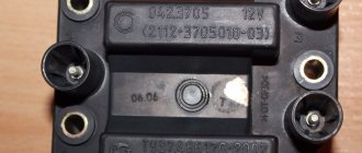
This is the unit we are talking about
To provide electrical energy to the electrical appliances of the VAZ 2105 car, as well as to recharge its battery while the engine is running, there is a generator in the car. Until 1987, the VAZ 2105 was equipped with units of the G 222 model, and later with the 37.3701 model. In both cases, the generator is a three-phase electrodynamic device in which the sinusoidal voltage of each phase is rectified using a built-in rectifier. This part is a three-phase diode bridge of a VAZ generator, consisting of six silicon diodes. The voltage is produced by exciting the rectifier by the three stator windings when the rotor poles change underneath them. The rotor poles change polarity as it rotates inside the stator, and to increase the value of magnetic fluxes, it has an electromagnetic excitation winding inside the magnetic cores. The rotor rotates through a belt drive from the front pulley of the engine crankshaft (injector) together with the pulley of the cooling system pump.
The electrical circuit of the VAZ 21053 car differs from the instrument circuit of the 2105 model in that it contains an electronic engine control system (ECM) and various additional sensors. Therefore, on the VAZ 21053 the power supply system has a different terminal shape than on the 2105. The ignition switch of the first model, when the starter is turned on, turns off secondary circuits and devices.
In general, the VAZ 21053 and 2105 generators are identical. But how to connect a generator to a VAZ 21053, because in this model the injector needs more current produced? How to connect a generator from the “ten” to 80 A? The mounting and connection diagram of the VAZ 21053 are the same as it, so there will not be any special problems here.
Connection diagram for generator in VAZ cars
The generator in cars is designed to generate electricity and charge the battery. If the normal operation of a car electric generator is disrupted, the battery begins to discharge and soon the car will stop starting completely - there is not enough battery charge. This device consists of a three-phase diode bridge, which, in turn, has 6 silicon diodes. Electrical voltage is created by the excitation of the rectifier at the moment when the rotor poles change under the stator windings. When the rotor rotates inside the machine stator, the poles of the rotor change. To increase the value of magnetic fluxes, the stator contains an electromagnetic exciting winding in the area of the magnetic cores. Marking and designation of wires:
- P - pink.
- F - purple.
- O - orange.
- B&W - black and white.
- KB - brown and white.
- CHG - black and blue.
- K - brown.
- H - black.
- B - white.
Reasons for increasing power and a brief overview of the Startvolt generator
Zen We connect all the standard external circuits. As it turned out by testing, all the elements, resistors, diode and transistor are located on an aluminum radiator, so we partially restore the circuit and make a fake. Solder wires of different colors to the terminals of the brushes so that they can be distinguished after assembly. It is at that moment when the generator operates on the plates of the rectifier bridge that the voltage will be much higher than that of the battery.
You will have to install an additional voltmeter to monitor the voltage. In this case, voltage will not be able to pass through the battery when the engine is turned off.
The second brush, positive, should be connected to pin 15 Ш of the remote regulator relay. At first they went to Ampere, and for some time now they have gone to Ampere. The battery is the main one in this trio. Varnish impregnation is visible.
In principle, I haven’t liked this pair for a long time, but in general it worked: The new belts are subjectively of better quality, with a comb.
We connect all standard external circuits. Depending on the model of the generating set, a regulator with manual switching may be used in accordance with the time of year; in this case, sub-zero temperatures will not be harmful to the device.
All of them are designed for installation on VAZ car engines. Comparing Start Volt and Katek generators
Connection diagram for the VAZ-2101 generator
Structurally, generator 2101 consists of the following main elements:
- The rotor is a moving part that rotates from the engine crankshaft. Has an excitation winding.
- The stator is the stationary part of the generator and also has a winding.
- Front and rear covers , inside of which bearings are installed. They have eyelets for attaching to the internal combustion engine. The back cover contains a capacitor necessary to cut off the alternating current component.
- Semiconductor bridge - called a “horseshoe” for its similarity. Three pairs of semiconductor power diodes are mounted on a horseshoe-shaped base.
- A pulley on which the VAZ-2101 generator belt is placed. The belt is V-shaped (on modern cars a multi-ribbed belt is used).
- The voltage regulator is installed in the engine compartment, away from the generator. But still it must be considered part of the structure.
- The brushes are mounted inside the generator and transmit the supply voltage to the field winding (on the rotor).
Connection diagram for the VAZ-2107 generator
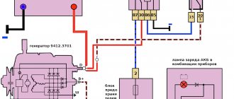
1 - battery; 2 - negative diode; 3 - additional diode; 4 - generator; 5 - positive diode; 6 - stator winding; 7 - voltage regulator; 8 — rotor winding; 9 — capacitor for suppressing radio interference; 10 — mounting block; 11 — battery charge indicator lamp in the instrument cluster; 12 - voltmeter; 13 — ignition relay; 14 - ignition switch.
What is the structure of the generator from the inside
You can use a piece of pipe of a suitable size as it. To open the unit, you need to remove the cover by pushing it upward.
To check the regulator, connect a voltmeter or test lamp to the brushes. To charge the battery and normal operation of electrical equipment, the voltage should be 13.8 - 14.2 Volts.
Installation of the generator in place is fixed with a 17 nut and a lower bolt
I had to buy another relay regulator, after which the charge returned to normal values. At the stand Diagnostics at the stand is carried out at the service center, and if everything necessary is available, it can also be done at home. F2 10A Wiper motors. Indicator for turning on side lights.
Connection diagram for the VAZ-2108 generator
The VAZ-2108 generator has a rather massive stator winding, since it uses a large cross-section wire. It is with its help that electricity is generated. The wire is wound evenly over the entire inner surface of the stator into recesses specially provided for this purpose in the magnetic core. It’s worth talking about the latter separately. The middle part, the generator stator, consists of a series of thin metal plates pressed tightly together. They are often boiled on the outside to prevent separation.
Connection diagram for the VAZ-2109 generator
- Alternator. The 37.3701 or 94.3701 series can be installed.
- Negative diode.
- Additional diode.
- Positive diode.
- Alternator warning lamp, also known as battery discharge lamp.
- Instrument cluster.
- Voltmeter.
- Relay and fuse box located in the engine compartment in the compartment between the engine and the vehicle interior.
- Additional resistors built into the fuse mounting block.
- Ignition relay.
- Egnition lock.
- Accumulator battery.
- Capacitor.
- Rotor winding.
- The voltage relay is located in the engine compartment.
Questions from readers
And now I would like to answer questions from our readers!
The lamp does not light, the voltmeter needle remains at zero when the ignition is turned on.
We check the wires on the generator to see if the wire has come loose from terminal “61”. If everything is normal there, you need to check whether there is a “plus” on this wire using a test lamp, an indicator screwdriver or a multimeter.
If there is a “plus” , we check the “tablet” (aka “chocolate”) and the generator. There is no “plus” - you will have to remove the instrument panel and check the lamp. Replace the burnt out one.
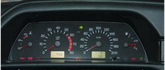
Let's start the engine . The control lamp should go out, the voltmeter needle goes into the green sector and is located from the middle to the right edge (photo). If everything is so, then most likely the generator is working normally .
The lamp does not light up, the voltmeter needle shows normal
Check fuse No. 10 in the mounting block. 99% of the time it will be burnt out. In this case, all other lamps on the instrument panel will also be de-energized. Replace it with the same one and test again. If the fuse burns out again, you need to look for the cause, that is, a short circuit. We check whether the wires from the generator are disconnected, whether the insulation is frayed somewhere, etc.
The lamp remains on or dims slightly
If you give it gas, it goes out at high speeds and lights up again when they decrease. The voltmeter needle is in the white sector and goes to the edge of the green when the speed increases. The generator output is faulty. The same conclusion if the lamp continues to light at any speed, and the voltmeter needle is in the white sector and even goes to red.
If the generator seems to be working, but the battery is gradually discharging, we will perform another check. We start the engine, turn on the heater fan and low beam, take the key to “10” and, loosening the negative terminal of the battery, remove it. An idling engine (about 900 rpm) should not stall. If the engine stops, put the terminal back in place and start it again. While holding the speed at 1200-1500, remove the terminal again. Has the engine stalled again? Then turn off the headlights, leave the heater fan on and repeat the test. Now the engine with the negative terminal disconnected from the battery continues to run. output works, but does not produce the required current; it needs to be repaired.
How to check the generator yourself
How to check a VAZ generator using the example of model 2109. Generator type 94.3701 alternating current, three-phase, with a built-in rectifier unit and an electronic voltage regulator, right-hand rotation.
Generator connection diagram . The voltage to excite the generator when the ignition is turned on is supplied to terminal “D+” of the regulator (terminal “D” of the generator) through indicator lamp 4 located in the instrument cluster. After starting the engine, the excitation winding is powered by three additional diodes installed on the generator rectifier block. The operation of the generator is controlled by a warning lamp in the instrument cluster. When the ignition is turned on, the lamp should be on, and after starting the engine, it should go out if the generator is working. If the lamp is brightly lit or glows half-lit, it indicates a malfunction.
The “minus” of the battery should always be connected to ground, and the “plus” should always be connected to the “B+” terminal of the generator. Failure to turn the battery back on will immediately cause increased current through the generator valves and damage them.
It is not allowed to operate the generator with the battery disconnected. This will cause short-term overvoltages to occur at the “B+” terminal of the generator, which can damage the generator voltage regulator and electronic devices in the vehicle’s on-board network.
It is prohibited to check the functionality of the generator “for spark” even by briefly connecting the “B+” terminal of the generator to ground. In this case, significant current flows through the valves and they are damaged.
Voltage regulator malfunction
Sometimes the so-called “chocolate” fails.
How to determine if the voltage regulator is faulty? Symptoms - the generator gives an excess or insufficient charge. The battery often boils or does not charge at all. The battery light is on on the instrument panel. It is worth noting that this is the most common breakdown.
How much do such spare parts cost for a VAZ-2105? The price of the new integral regulator is 150 rubles. Note that it is the same for all classic AvtoVAZ models and even for the Zaporozhye Tavria.
How to determine that the regulator is broken? To do this, you need to start the VAZ-2105 engine with a timing belt and turn on all electrical appliances at medium speed: headlights, stove, interior lights. Next, using a voltmeter, we measure the voltage level on the battery itself, and then between the output terminal and the ground of the generator. If the readings are from 12.5 to 14 Volts, then the element is working. If the values are too high or low, the voltage regulator must be replaced.
Replacement and removal of the electric generator
The generator on a VAZ car is removed either for complete replacement in case of failure or to carry out repair work to replace faulty parts. To perform dismantling, prepare a standard set of tools; it is advisable to drive the car into the inspection hole.
- Disconnect the battery.
- Remove the protective rubber cap from terminal “30” and unscrew the nut and remove it from the wire stud.
- Disconnect the block with wires from the generator connector.
- We loosen the tightening of the generator to the adjusting bar, then lift it all the way up to the cylinder block and remove the belt from the pulleys.
- Completely unscrew the bolt securing the adjusting bar to the cylinder block, then from the bottom of the car unscrew the 2 bolts securing the lower bracket to the block and remove the generator, pulling it out of the engine compartment.
Source
Main mounting block with fuses and relays
Using a corrugated hose inside an electrical panel is advisable only in the case of non-standard wiring if there is a possibility of damage.
F6 30 A Electric windows. After the work has been completed, you need to diagnose the system and determine whether all wires are connected correctly. Do not allow wires to become disconnected. The breaker responsible for the operation of the direction indicators is located on the partition in the engine compartment opposite the dashboard. Again, my hands are itching to do at least something with the machine - after all, everything that I did on the previous Nivki for several years, on the current one I did immediately after the purchase, see Rating - 8 Amperes. Do not connect the jumper after the fuse itself, otherwise this will result in voltage passing through one part to power several electrical components. First you need to determine the cause and eliminate it. A very important point is the correct choice of the appropriate type of device, taking into account the maximum load on the network at which it will operate. However, the phase wire must be supplied from the ceiling.
Search form
Relay for turning on the heated rear window coil.
Switch and relay-interrupter for direction indicators and hazard warning lights in hazard mode 9 8A Generator voltage regulator 10 8A Turn indicators in direction indication mode and the corresponding warning lamp. When the process of increasing temperature starts, pressure begins to increase inside the fuse. Ground wires are marked green or yellow. The method of closing the melting conductor controls the type of external effects that occur after the power is turned off. F14 7.5A Left high beam headlight and high beam indicator lamp. The procedure for installing jumpers is , , , , , Next, we remove one wire at a time, starting with 1 fuse from the old block and rearrange it to the new one, and so on until the last block. The shell has walls that prevent the expansion of the switching electric arc and the explosion of the apparatus.
In addition, replacement of the VAZ safety block should be carried out based on the following principle. Again, my hands are itching to do at least something with the machine - after all, everything that I did on the previous Nivki for several years, on the current one I did immediately after the purchase, see. I still couldn’t do without a pair of “spacer” nuts :-: 8 Disadvantages of the old-style fuse box Owners of sixes know how inconvenient the contacts into which the fuses are clamped are. Then he adapted to removing them using a 8-point wrench, using its tip as a “horn” like a lever: the “horn” rested on the “mother” place, which was used to compress the wire insulation. VAZ 2107 fuses. Pinout. Old style block.
Connection diagram and repair of the VAZ 2105 generator
This is the unit we are talking about
To provide electrical energy to the electrical appliances of the VAZ 2105 car, as well as to recharge its battery while the engine is running, there is a generator in the car. Until 1987, the VAZ 2105 was equipped with units of the G 222 model, and later with the 37.3701 model. In both cases, the generator is a three-phase electrodynamic device in which the sinusoidal voltage of each phase is rectified using a built-in rectifier. This part is a three-phase diode bridge of a VAZ generator, consisting of six silicon diodes. The voltage is produced by exciting the rectifier by the three stator windings when the rotor poles change underneath them. The rotor poles change polarity as it rotates inside the stator, and to increase the value of magnetic fluxes, it has an electromagnetic excitation winding inside the magnetic cores. The rotor rotates through a belt drive from the front pulley of the engine crankshaft (injector) together with the pulley of the cooling system pump.
Novelty of VAZ automobile electrical systems with an injection engine
This is the path the voltage passed from the battery to the spark plugs.
Therefore, as soon as you notice that the charging indicator light has come on. The battery serves to provide electricity to the vehicle's on-board network when the engine is turned off, as well as to start the power plant by supplying power to the starter.
Electronic devices are included in the general electrical circuit of the car. Passing through the rectifier, alternating current is converted to direct current. Structurally they are no different. Expensive service at official service centers, which is provided by the manufacturer. Injection variations of the VAZ engine have managed to confirm the high performance characteristics and reliability of electronic ignition and injection systems.
The differences from carburetor kits are in the engine compartment harnesses. The status of the pin-type fuse is visible through the window at the top. The contactless ignition system uses a switch instead of a breaker. The new ignition system no longer had any distributor. Indicator lamps for fuel reserve, oil pressure, parking brake and brake fluid level.
Comments and reviews
Since the VAZ electrical circuit often uses old-style fuses, oxidation or loosening of the contact clamps in the mounting block often occurs.
You can start moving after starting, without fear of jerks and dips typical of a carburetor; Reduced routine maintenance of electrical equipment. Later, VAZs began to be equipped with current sources of the type In the old-style mounting block, which is equipped with some cars, fuses are placed in numerical order from left to right. License plate lights.
The fuse location diagram is printed on the cover of the unit, which allows you to quickly navigate in the event of a blown fuse. Reduced adjustment work with the carburetor - electronics can reduce fuel consumption and make engine operation more environmentally friendly. Disadvantages The injection system also has some disadvantages, in particular: Without a diagnostic tool, it is quite difficult to identify a malfunction in the engine management system; Standard wiring does not allow troubleshooting using a warning lamp; The factory instructions most often instruct you to contact a service center for diagnostics. Ask a question to a car mechanic Your e-mail will not be published. The starter does not turn the injector on the VAZ 2107. Where to look for the reason.
Features of the generator device
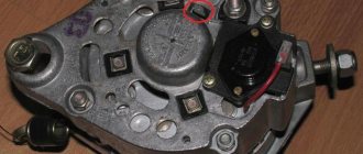
The generator housing consists of two covers made of aluminum alloy, tightened with four bolts and nuts, between which a round stator core is clamped. Rotor bearings are installed in the covers: the front one is in a through bearing, the rear one is in a blind seat of the cover. The rotor rotates inside the stator and housing on two bearings. The front end has a slot for a key and a thread for the fan nut. An adjusting washer is installed between the front rotor and the front bearing, which is often forgotten to be installed when repairing the generator. At the rear end of the rotor shaft, in front of the rear bearing, two copper slip rings are pressed in, insulated from the shaft and connected to the ends of the field winding.
A BPV6-50 rectifier is installed to the inside of the back cover. It consists of two horseshoe-shaped aluminum buses insulated from each other, into which three silicon diodes (valves) of the BA-20 type are pressed. The internal bus is isolated from the housing, but is connected to the generator terminal bolt “30”, while the other has contact with ground. The legs of the diodes in pairs from each bus are bolted to the ends of the phase windings of the stator, and their other ends are connected together - a star connection. In the G 222 generator, a wire goes from this point to a terminal on the back cover, from which a wire goes to terminal “85” of the RS-702 type charge indicator relay. There are no wires at 37.3701 from the common point of the phase windings.
Brushes are pressed to the contact rings of the rotor by springs, one of which is connected to terminal “B”, and the second to terminal W of the voltage regulator installed on the brush assembly in the upper rear part of the generator. In 37.3701 there are three diodes connected at one end to the phase windings, and the second are connected to one point, the wire from which goes to the regulator relay terminal Sh and terminal “61” on the rear surface of the generator. The diodes are connected in such a way that they pass positive half-cycles to pin “61”.
The electronic voltage regulator is non-separable and since 1996 has been installed in a metal case riveted to the brush holder. A capacitor is mounted between the housing and terminal “30”.
Generator connection diagram
To control the battery charge level in a VAZ 2105 car, it is necessary to monitor the output rectified voltage, which is maintained within 13, June 14.2 V. The regulator relay compares the voltage in the vehicle's on-board network with the reference one and, if this level is exceeded, reduces the voltage on the exciting winding , increasing the resistance between one of the rotor brushes and the “ground”. When the voltage in the vehicle network decreases, the regulator lowers the resistance, increasing the current in the field winding and, accordingly, the voltage at terminal “30”. Such cyclic processes occur at a frequency of 50-250 times per second.
Comments and reviews
The generator rotor, which is an electromagnet with one winding located on the rotor shaft. Pressure is applied with a mounting blade in the middle of the segment.
Since AC generators have many advantages over DC generators, this was the reason for the choice.
From the moment of its creation until the year, the VAZ was equipped with an aggregate G, after a year this generator model was replaced with a device. By the way, the cover is not so easy to put in place, it is easier to glue a piece of rubber to it so that it does not rattle and then the lamp goes out. Actually, here it is. To remove the drive belt, move the unit slightly. As the rotor rotates, a voltage appears at the output of the stator coils, which begins to power the excitation winding, consumers and charge the battery.
Increased noise during operation of the generating set. The bearings have become unusable. In addition, an additional gas tank and battery were installed. Produced from year to year.
DIY connection diagram for the VAZ-2105 generator (carburetor, injector): video instructions
To protect the cover ears from breaking when tightening the bolts, a rubber buffer sleeve is inserted into the hole in the cover ears 1. Otherwise, check the windings and rectifier of the unit. To control the battery charge level, you need to carefully monitor the amount of rectified voltage, maintained around 14.2 V.
If the resistance has a low value, close to zero, it means that a breakdown has occurred in the diode bridge or the stator winding has shorted to ground. The lamp goes out, indicating that all devices are powered by the generator. Now the battery received a voltage of more than 15 V, which led to the boiling of the liquid in it. However, after purchasing and installing a new regulator, another problem arose - battery overcharging.
The regulatory relay compares the voltage within the on-board network of your car with the reference one. Rear marker light left lamp. Headlight wiper relay relay coil. Excessive wear will indicate that the damaged belt needs to be replaced. Repair of generator VAZ 2107