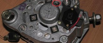
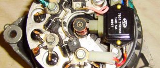
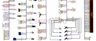
Generator 9412.3701 is installed on a Niva 21214i car with an injection engine. We present the electrical diagram of its connection.
Notes and additions
— On a Niva 21213 car with a carburetor engine, a 371.3701 generator with a slightly different connection diagram is installed.
More articles on the Niva 21214i car
— Diagram of the engine control system (ECM) of the Niva 21214I
Device Description
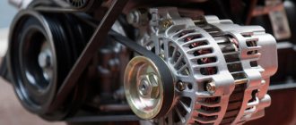
On Niva 21214 cars there is a generator of type 9412.3701, on VAZ 21213 - type 371.3701, on Niva Chevrolet there is a generator 2123. All of them are alternating current electric machines with electromagnetic excitation, having a built-in rectifier unit with silicon diodes and an electronic voltage regulator. The maximum current produced by the generator unit type 9412.3701 is 80 A, voltage - 13.2 - 14.7 V, rotation - right.
Design of unit 21214
The unit covers are attached to the stator using 4 bolts. The covers have bearings installed. They rotate the rotor shaft. In the front bearing, the inner race is clamped with a nut along with a thrust ring and washer. The 2nd bearing is also pressed into the back cover.
The stator has a 3-phase winding, one of the ends of which is connected to a rectifier unit consisting of 6 diodes. Of these, 3 diodes are negative, 3 are positive. According to the polarity, they are pressed into the plates. The entire structure consists of a rectifier unit, which is located on the back cover of the generator unit covered with a protective casing.
The design of the unit also includes contact rings and brushes. On the back side of the back cover there is a brush holder, which is structurally connected to the voltage regulator. The rectifier contains a capacitor that protects the electrical network from power surges.
The “B” terminal of the generator set must be connected to the positive terminal of the battery, and the negative terminal of the battery to the vehicle ground. If the connection is incorrect, this will lead to breakdown of the diodes.
Generator Niva 21214
Dismantling and connecting the generator on Niva 2121: step-by-step instructions
The generator is the source of electrical energy for the vehicle. The article discusses the 21214 generator, its design features, possible problems and troubleshooting methods, and provides step-by-step instructions on how to remove and connect the device.
On Niva 21214 cars there is a generator of type 9412.3701, on VAZ 21213 - type 371.3701, on Niva Chevrolet there is a generator 2123.
All of them are alternating current electric machines with electromagnetic excitation, having a built-in rectifier unit with silicon diodes and an electronic voltage regulator.
The maximum current generated by the generator unit type 9412.3701 is 80 A, voltage - 13.2 - 14.7 V, rotation - right.
Design of unit 21214
The unit covers are attached to the stator using 4 bolts. The covers have bearings installed. They rotate the rotor shaft. In the front bearing, the inner race is clamped with a nut along with a thrust ring and washer. The 2nd bearing is also pressed into the back cover.
The stator has a 3-phase winding, one of the ends of which is connected to a rectifier unit consisting of 6 diodes. Of these, 3 diodes are negative, 3 are positive. According to the polarity, they are pressed into the plates. The entire structure consists of a rectifier unit, which is located on the back cover of the generator unit covered with a protective casing.
The design of the unit also includes contact rings and brushes. On the back side of the back cover there is a brush holder, which is structurally connected to the voltage regulator. The rectifier contains a capacitor that protects the electrical network from power surges.
The “B” terminal of the generator set must be connected to the positive terminal of the battery, and the negative terminal of the battery to the vehicle ground. If the connection is incorrect, this will lead to breakdown of the diodes.
Generator Niva 21214
We recommend: How to properly change the timing belt on a Kia Spectra on your own?
Basic malfunctions and ways to eliminate them
Checking the health of the unit is done using a multimeter. After the engine is started, the voltage at the battery terminals should be 13.6 V. If the value is higher or lower, this indicates a break or short circuit of the windings, oxidation of the slip rings, a malfunction in the brush assembly, or voltage regulator.
The generator unit may not work well due to weak belt tension or its breakage. In this case, you need to adjust the tension or replace the belt. Faulty voltage regulator, needs to be replaced.
If a breakdown, short circuit, or damage to the rotor windings is detected, it should be replaced. If there is a break or short circuit in the stator windings, it requires replacement. If the diodes are damaged, the rectifier unit is replaced.
Nuances of moving a generator
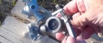
The disadvantage of domestic Niva SUVs is the location of the generator unit - at the bottom of the engine compartment. It constantly gets contaminated when driving off-road, and coolant constantly drips. The problem is solved by moving the generator upstairs (the author of the video is SARTANETS).
To transfer, you will need a set of keys, a bracket, mounting bolts, and a V-belt. You can make a generator transfer bracket with your own hands according to the drawing below.
Drawing of a homemade bracket
Sequence of actions during transfer:
- We dismantle the propeller, pump and remove the belt.
- By unscrewing the standard bracket, you can remove the generator.
- We cut off the bead around the side of the cylinder head and on the cylinder block.
- Then you should unscrew the two bolts and two studs.
- Next, the assembly is installed on a new bracket and final assembly is performed.
1. Schematic illustration of unscrewing the fastening material
2. Car with the belt removed
3. Unit in a new location
Thus, moving the generator unit upstairs is not difficult.
Basic malfunctions and ways to eliminate them
Checking the health of the unit is done using a multimeter. After the engine is started, the voltage at the battery terminals should be 13.6 V. If the value is higher or lower, this indicates a break or short circuit of the windings, oxidation of the slip rings, a malfunction in the brush assembly, or voltage regulator.
The generator unit may not work well due to weak belt tension or its breakage. In this case, you need to adjust the tension or replace the belt. Faulty voltage regulator, needs to be replaced. If a breakdown, short circuit, or damage to the rotor windings is detected, it should be replaced. If there is a break or short circuit in the stator windings, it requires replacement. If the diodes are damaged, the rectifier unit is replaced.
content .. 91 92 95 ..VAZ-21213 (Niva). Generator 37.3701
Technical characteristics
Generator 37.3701 1 – cover on the side of the slip rings; 2 – rectifier block; 3 – rectifier block valve; 4 – screw for fastening the rectifier unit; 5 – contact ring; 6 – rear ball bearing; 7 – capacitor; 8 – rotor shaft; 9 – output “30” of the generator; 10 – output “61” of the generator; 11 – terminal “B” of the voltage regulator; 12 – voltage regulator; 13 – brush;
| 14 – stud securing the generator to the tension bar; 15 – pulley with fan; 16 – rotor pole piece; 17 – spacer sleeve; 18 – front ball bearing; 19 – drive side cover; 20 – rotor winding; 21 – stator; 22 – stator winding; 23 – rotor pole piece; 24 – buffer sleeve; 25 – bushing; 26 – clamping sleeve |
Generator type 37.3701 – alternating current, three-phase, with built-in rectifier unit and electronic voltage regulator, right rotation (drive side). To protect against dirt, the rear cover of the generator is closed with a protective casing 4 (see Fig. Removing the protective casing of the generator). Various design options for the protective casing and air intake are possible. Stator 21 and covers 1 and 19 are secured with four bolts. The rotor shaft 8 rotates in bearings 6 and 18, which are installed in the covers. Power is supplied to the rotor winding (excitation winding) through brushes and slip rings 5. The three-phase alternating current induced in the stator winding is converted into a constant current by rectifier unit 2 attached to cover 1. Electronic voltage regulator 12 is combined into one unit with a brush holder and is attached also to cover 1. Generator connection diagram
| 1 – battery; 2 – generator; 3 – instrument cluster; 4 – resistor 51 Ohm, 5 W; 5 – diode; | 6 – battery charge indicator lamp; 7 – fuse block; 8 – ignition relay; 9 – ignition switch |
The voltage to excite the generator when the ignition is turned on is supplied to terminal “B” of the regulator (terminal “61” of the generator) through fuse 2 and warning lamp 6 located in instrument cluster 3. After starting the engine, the excitation winding is powered by three additional diodes installed on the rectifier block generator The operation of the generator is controlled by indicator lamp 6 in the instrument cluster. When the ignition is turned on, the lamp should be on, and after starting the engine, it should go out if the generator is working. A bright burning lamp or its glow at full intensity indicates a malfunction in the generator system. Until 1995, the voltage in the vehicle's electrical system was controlled by an electronic voltmeter in the instrument cluster. When it was normal, the voltmeter LED did not light up. If the voltage was higher than normal, the LED blinked, and if it was low, it glowed constantly. Since 1996, the design of the voltage regulator and brush holder has been changed. Now the voltage regulator is placed in a metal case and riveted to the brush holder, i.e. forms an inseparable knot with it. The new voltage regulator does not have terminal “B” and voltage is supplied only to terminal “B”. In terms of their characteristics, the old and new voltage regulators are the same and, when assembled with a brush holder, are interchangeable. Small batches of cars can be equipped with generators made in Slovenia, Bulgaria or Germany. These generators are interchangeable with the 37.3701 generator in terms of characteristics and installation dimensions, but differ slightly in design. This chapter describes only the domestic generator 37.3701, as the main one for VAZ-21213 cars. Warning
The “minus” of the battery should always be connected to ground, and the “plus” should always be connected to terminal “30” of the generator. Failure to turn the battery back on will immediately cause increased current through the generator valves and damage them. It is not allowed to operate the generator with the battery disconnected. This will cause short-term overvoltages to occur at terminal “30” of the generator, which can damage the generator voltage regulator and electronic devices in the vehicle’s on-board network. It is prohibited to check the functionality of the generator “for spark” even by briefly connecting terminal “30” of the generator to ground. In this case, significant current flows through the valves and they are damaged. The generator can only be checked using an ammeter and voltmeter. The generator valves are not allowed to be checked with a voltage of more than 12 V or with a megger, since it has a voltage too high for the valves and they will be broken during testing (a short circuit will occur). It is prohibited to check the vehicle's electrical wiring with a megger or a lamp powered by a voltage of more than 12 V. If such a check is necessary, you must first disconnect the wires from the generator. The insulation resistance of the generator stator winding with increased voltage should be checked only on a stand and always with the terminals of the phase windings disconnected from the valves. When electrically welding components and parts of the car body, you should disconnect the wires from all terminals of the generator and battery.
| Maximum output current (at 13 V and 5000 min–1), A | 55 |
| Adjustable voltage limits, V | 14,1 ± 0,5 |
| Maximum rotor speed, min–1 | 13000 |
| Engine/generator ratio | 1/ 2,04 |
content .. 91 92 95 ..
Nuances of moving a generator
The disadvantage of domestic Niva SUVs is the location of the generator unit - at the bottom of the engine compartment. It constantly gets contaminated when driving off-road, and coolant constantly drips. The problem is solved by moving the generator upstairs (the author of the video is SARTANETS).
To transfer, you will need a set of keys, a bracket, mounting bolts, and a V-belt. You can make a generator transfer bracket with your own hands according to the drawing below.
Drawing of a homemade bracket
Sequence of actions during transfer:
- We dismantle the propeller, pump and remove the belt.
- By unscrewing the standard bracket, you can remove the generator.
- We cut off the bead around the side of the cylinder head and on the cylinder block.
- Then you should unscrew the two bolts and two studs.
- Next, the assembly is installed on a new bracket and final assembly is performed.
Thus, moving the generator unit upstairs is not difficult.
Charging circuit diagram and typical problems
Before finding out why charging disappeared on the Niva VAZ 2121, 21213, 21214 injector, 2131 and 2123 (aka LADA Niva and Niva Chevrolet), let’s look at the circuit diagrams of the charging circuit of these models and the principle of their operation. Otherwise, you will have to search at random, and this is a bad method.
VAZ 2121
Let's start with the oldest, because age must be respected. Let's take a look at the diagram below.
The numbers on the diagram indicate:
- - accumulator battery;
- – generator with built-in rectifier bridge;
- – relay-regulator;
- – ignition switch (lock);
- – fuses in the mounting block;
- – indicator lamp for lack of charging;
- – warning lamp relay.
When the ignition switch is turned on, the voltage from the battery through the fuse and the normally closed contacts of the voltage regulator relay is supplied to the generator excitation winding. The relay regulator does not operate yet, since the voltage in the on-board network is below the normal level for charging. At the same time, through the second fuse, the same voltage is supplied to the battery charging control unit, assembled on an electromagnetic relay with normally closed contacts.
Since the generator is not producing anything yet, there is nothing at its middle point of connection of the windings - all the rectifier diodes are locked, it seems to be hanging in the air. As a result, the control unit relay also does not work and the “no charging” lamp is on.
Now we start the engine, the generator begins to generate voltage, which is rectified, charges the battery and powers the on-board network. At this time, at the connection point of the windings, which is essentially the neutral wire, a low potential is established relative to the positive wire of the on-board network. The relay is activated and extinguishes the control lamp.
The voltage level from the generator is monitored by a relay regulator. As soon as it exceeds the critical value (14.2 V), the relay will operate, its contacts will open and a reduced voltage will be supplied to the excitation winding, which means the voltage in the on-board network will also decrease. It becomes below normal (13.5 V), the relay will release again, and the process will repeat.
VAZ 21213, 21214, 2131, 2123
Now let's talk about other modifications of the Niva. All four remaining modifications of the car have the same charging circuit, shown in the figure below.
The numbers on the diagram indicate:
- - accumulator battery;
- – generator with built-in rectifier and relay regulator;
- – instrument cluster;
- – resistor;
- – diode switch;
- – indicator lamp for lack of charging;
- – fuse in the mounting block;
- – ignition relay;
- - egnition lock.
The schemes are very similar, but there are still differences. When the ignition is turned on, voltage from the battery is supplied to the ignition relay, and it is activated. The same voltage, through the normally closed contacts of the relay, is supplied to the charging control unit and from it to the relay-regulator as the initial bias of the excitation winding. An additional 12 V from the battery is supplied to the same relay-regulator built into the generator. In this case, the charging control lamp lights up, since its second output is connected to ground through an open diode and a small resistance (51 Ohms).
We start the engine, the generator rotates. The voltage it creates through additional decoupling diodes (on the left in the diagram) is supplied to the control output of the relay regulator. Based on this voltage, the relay-regulator controls the generator, changing the current in the excitation winding in one direction or another so that the voltage in the on-board network remains at the required level.
Important! The same voltage is applied to the cathode of the charge control diode. It locks and the light goes out.
Well, now let's talk about typical malfunctions of charging circuits and start, of course, with a false alarm that the charging control lamp can raise.
Guide to removing and connecting the generator
To remove the unit, you need to prepare a set of tools: keys “10” and “19”, ratchets with heads, a hammer and a small extension.
The process consists of the following steps:
- First of all, remove the negative terminal from the battery.
- Next, you need to remove the engine protection and the right mudguard.
- Then, using a hammer, carefully knock out the mounting bolt and remove it.
- At the next stage, you need to disconnect all the wires going to the generator: the plug and the wires secured with a nut.
- Then the fastening on which the belt tensioner is located is unscrewed.
- By removing the belt, the assembly can be dismantled through the hole that was formed after removing the protection.
- After replacement or repair, install the unit in reverse order.
Diagram of the VAZ-21213 car
Electrical diagram of VAZ-21213 (Carburetor). Years of manufacture: 1993-2009. The diagram shows a relay for rear fog lights, used since 2000; before that they were turned on directly from a latching switch.
1 – front lights; 2 – side direction indicators; 3 – windshield washer electric motor; 4 – headlight washer electric motor*; 5 – switch; 6 – battery; 7 – starter; 8 – generator; 9 – VAZ-21213 headlights; 10 – gearmotors for headlight cleaners*; 11 – sound signal; 12 – spark plugs; 13 – carburetor limit switch; 14 – carburetor solenoid valve; 15 – ignition coil; 16 – windshield wiper gearmotor; 17 – carburetor solenoid valve control unit; 18 – ignition distributor sensor; 19 – coolant temperature indicator sensor; 20 – oil pressure warning lamp sensor; 21 – plug socket for a portable lamp**; 22 – brake fluid level warning lamp sensor; 23 – windshield wiper relay; 24 – relay for turning on the rear fog light***; 25 – relay for turning on the heated rear window; 26 – relay for turning on headlight cleaners and washer*; 27 – relay for turning on low beam headlights; 28 – relay for turning on the high beam headlights; 29 – ignition relay VAZ-21213; 30 – starter activation relay; 31 – relay-breaker for alarm and direction indicators; 32 – heater electric motor; 33 – additional resistor of the heater electric motor; 34 – backlight lamps for heater control levers; 35 – external lighting switch; 36 – main fuse block; 37 – additional fuse block; 38 – reverse light switch; 39 – brake light switch; 40 – instrument lighting regulator; 41 – ignition switch; 42 – three-lever switch; 43 – alarm switch; 44 – tailgate glass cleaner and washer switch*; 45 – heater motor switch; 46 – switch for heating the rear door glass; 47 – rear fog light switch; 48 – lamp switches located in the door pillars; 49 – interior lamps; 50 – Niva cigarette lighter; 51 – switch for the warning lamp for closing the carburetor air damper; 52 – control lamp for covering the carburetor air damper; 53 – switch for the differential lock warning lamp; 54 – parking brake warning lamp switch; 55 – sensor for level indicator and fuel reserve; 56 – instrument cluster; 57 – tailgate glass washer motor; 58 – rear lights; 59 – block for connecting additional brake lights; 60 – blocks for connecting side marker indicators; 61 – pads for connecting to the heated glass element of the tailgate; 62 – license plate lights; 63 – rear door glass wiper motor.
The order of conditional numbering of plugs in blocks:
a – windshield wipers, headlights and tailgate glass, windshield wiper relay breaker; b – ignition distributor sensor; c – relay-interrupter for alarm and direction indicators; d – switch VAZ-21213; d – three-lever switch; e – alarm switch; g – relay for turning on the rear fog light; h – rear lights (pin numbering in order from top to bottom); and – instrument clusters.
In the instrument panel wiring harness, the second ends of the white wires are brought together to one point, which is connected to the instrument lighting control. The second ends of the black wires are also brought together to a point connected to ground. The second ends of the yellow wires with a blue stripe are brought together to a point connected to terminal “A” of the main fuse block. And the second ends of the orange wires are also brought together to a point connected to terminal “B” of the main fuse block.
What is a generator suitable for Niva 4x4?
For injection VAZ 2121, a generator from Niva-Chevrolet until 2003 is suitable. Select a generator according to the characteristics and catalog numbers indicated in the table:
| Manufacturer | Name | Power, W | Max. current, A |
| VAZ 2121 – generator 2101-3701010 (G221A) | |||
| KZATE | G221A.3701 | 590 | 42 A |
| ELDIX | ELD-A-2101-14V-50A | 700 | 50 A |
| StartVOLT | LG 0101 | 1200 | 85 A |
| Carburetor VAZ 21213, VAZ 2131, VAZ 2120 – generator 21213-3701010 | |||
| KZATE | 371.3701-02 | 770 | 55 A |
| Injection VAZ 21214, VAZ 2131 – generator 21214-3701010 | |||
| KZATE | 9412.3701 | 1120 | 80 A |
| ELDIX | ELD-A-21214-14V-90A | 1400 | 100 A |
| ELDIX | ELD-A-21214-14V-135A | 1850 | 135 A |
| PRAMO | 5142.3771 | 1120 | 80 A |
| PRAMO | 5142.3771-10 | 1400 | 100 A |
| StartVOLT | LG 01214 | 1970 | 135 A |
If you resort to modifications (make a different generator mount, replace a pulley), the list can expand significantly. It is not uncommon for VAZ 2121 owners to install more powerful generators from foreign cars in the engine compartment.
Which generator did you choose? Does it make sense to install a powerful generator on the Niva? Participate in the survey and leave feedback and recommendations for its choice in the comments. By the way, to protect the generator from moisture and dirt, it is moved upstairs. Let us remind you that other surveys on the choice of SUV components are in this category.
Keywords: Niva generator
