Carburetor engines
The connection diagram for the VAZ-2107 generator (carburetor and injector) depends on the year of manufacture of the car. The first carburetor models had a G-222 generator installed. The same device can be found on commercially produced VAZ-2105 and VAZ-2104 models with a carburetor injection system.
The maximum output current for such an installation is 55 amperes. But in recent years, cars with fuel injection systems have become widespread. Its use implies a large current consumption, so it is necessary to use a generator with a high current to ensure a normal charge level and power supply to all consumers.
DIY Generator Connection Guide
The reason for replacing a VAZ 2107 generator with an injector or carburetor may be:
- burnt windings;
- an interturn short circuit has occurred;
- mechanical damage to the housing;
- malfunction of a three-level regulator, etc.
The generator replacement procedure consists of removal, installation and connection.
- First of all, we de-energize the car by removing the negative terminal from the battery.
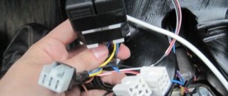
- Disconnect the connector from the generator set.
Disconnecting the connector from the unit - Having removed the protective cover, you need to disconnect the terminal with a “10” key and remove the wire.
- After loosening the generator, you need to remove the drive belt.
- Using a “17” wrench, unscrew the nuts and remove the adjusting bar.
- After unscrewing the lower fastening nut, remove the bolt and bushing.
- We dismantle the generator.
Unit removed for repair
The generator set is installed in the reverse order. Before installing the unit, you need to thoroughly study the connection diagram of the 2107 generator with an injector or carburetor, as well as the electrical connection diagram. In this case, you need to pay attention to the difference between 37.3701 and G222.
After installation, you need to adjust the belt tension. To adjust the belt tension, you need to loosen the two bolts securing the unit. Using a pry bar, tighten the belt and secure it in this position with a nut on the adjusting plate. Then you need to check the degree of tension. To do this, you need to press the belt in the gap between the pulleys.
The deflection should be in the front from 10 to 17 mm. The procedure should be repeated until the desired value is achieved. After tensioning, all fastening nuts are finally tightened. At this point, the connection of the unit can be considered complete.
Modern cars are equipped with a large number of electronics, so the generator must be powerful to provide power to the on-board network and the operation of network elements. Therefore, you need to carefully monitor its technical condition.
Injection engines
On injection engines, generator sets 5142.3771 or similar are used. They have increased energy, the maximum current is about 80-90 A, it all depends on the design option. Cars of the seventh series and similar models are good because they are like a designer set. You can install almost any generator on them, similar in design to the “native” one.
For tuning, installations with an output current of 100 amperes and higher are used. But the use of such devices is justified only if many powerful consumers are connected to the electrical equipment. Regardless of the design, the generators produce alternating current; a voltage regulator, capacitor and diode block are installed in the housing.
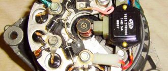
Generator device
The design of a car generator implies the presence of its own rectifier and control circuit. The generating part of the generator, using a stationary winding (stator), generates three-phase alternating current, which is then rectified by a series of six large diodes and the direct current charges the battery. Alternating current is induced by the rotating magnetic field of the winding (around the field winding or rotor). Next, the current is supplied to the electronic circuit through the brushes and slip rings.
Generator structure: 1.Nut. 2. Washer. 3.Pulley 4.Front cover. 5. Distance ring. 6.Rotor. 7.Stator. 8.Back cover. 9.Casing. 10. Gasket. 11.Protective sleeve. 12. Rectifier unit with capacitor. 13. Brush holder with voltage regulator.
The generator is located at the front of the car engine and is started using the crankshaft. The connection diagram and operating principle of a car generator are the same for any car. There are, of course, some differences, but they are usually associated with the quality of the manufactured product, the power and the layout of the components in the motor. All modern cars are equipped with alternating current generator sets, which include not only the generator itself, but also a voltage regulator. The regulator equally distributes the current in the excitation winding, and it is due to this that the power of the generator set itself fluctuates at a time when the voltage at the power output terminals remains unchanged.
New cars are most often equipped with an electronic unit on the voltage regulator, so the on-board computer can control the amount of load on the generator set. In turn, on hybrid cars the generator performs the work of the starter-generator; a similar circuit is used in other designs of the stop-start system.
Cars before 1986
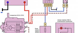
The G-222 generator was used in cars. The connection diagram for the VAZ-2107 is almost the same as on later models. But there are features, among the main ones - there is a control lamp indicating battery charging. Moreover, it worked using an electromagnetic relay.
When the ignition is turned on, power is supplied from the lock through the instrument panel fuse to the electromagnetic relay of the battery charge lamp and the coil contact. The second contact of the coil is connected to the center wire on the generator (the point where the three windings connect).
The electromagnetic relay has normally closed contacts, so when the ignition is turned on, the lamp lights up. But as soon as the engine starts running, the generator produces current. And a current flows through the control lamp coil, which causes the armature to attract and open the contacts.
At the same time, the power to the incandescent lamp stops and it goes out. This indicates that the battery is charging normally. Only when the power supply to the lamp stops will voltage be applied to the excitation winding and the generator will be able to return to operating mode.
How to independently connect a generator to a VAZ 2107?
Every G7 car owner should know what the generator set connection diagram is.
Despite the fact that this unit is quite reliable and has a long service life, sooner or later it will still fail, the reasons may be as follows:
- burnt out windings inside the unit;
- interturn short circuit formed in the system;
- damage and other defects in the device body, etc.
If you do not plan to repair the generator or the repair work is not successful, then you will need to replace the device.
To do this you need to do the following:
- First you need to turn off the power to the vehicle's on-board network. To do this, turn off the ignition, then open the hood and disconnect the negative terminal from the battery.
- Then you will need to find the generator itself - as we reported above, it is located on the right side of the power unit. Wires and a power cable with a plug are supplied to the generator - it must be disconnected. It is advisable to remember the location of the wires.
- Next, it is necessary to dismantle the mudguard on the right, as well as the motor protection, if any.
- Now comes the hard part. Using a wrench, you will need to unscrew the nut of the screw that secures the unit to the power unit housing. If you have difficulty unscrewing the nut, treat it with WD-40, after which the screw itself will need to be removed from its seat. Try hitting it with a hammer from the other side, but not too hard, this will knock out the bolt. If you were unable to remove the screw, you will have to dismantle the unit with the bracket on which it is fixed.
- To dismantle the bracket you will need to unscrew two screws; some modifications of the VAZ 2107 use three-screw fastenings. In any case, when performing these actions you must be guided by the design features of the vehicle. Sometimes, to remove the unit, you also need to remove the radiator device or move it a little to the side to gain access to the bracket. In this case, there is no need to disconnect the pipes connected to the radiator.
- After the unit is removed from its installation location, you will need to remove the drive belt and remove the generator.
- This way the knot is removed. To dismantle it, you must perform all these steps, only in reverse order. Before installing the device, you must familiarize yourself with the installation wiring diagram and the electrical connection diagram; all this must be indicated in the service book for the car.
- When the knot is installed, it is necessary to adjust the strap tension. To perform these steps, you will need to loosen the two screws that secure the assembly. Using a pry bar, you need to tighten the strap and secure it in the appropriate position with a nut located on the adjusting plate. When adjusting, be sure to check the degree of belt tension; to do this, press the belt in the free space between the pulleys. The belt will bend, and the deflection should be at least 1 cm and no more than 1.7 cm, otherwise the generator will not work correctly, and the belt may wear out earlier. When the adjustment procedure is completed, you need to tighten all the nuts.
Photo gallery “Changing the generator with your own hands”
Cars manufactured in 1996 and later (carburetor engines)
The connection diagram for the G222 generator on a VAZ-2107 after 1996 differs from the previous one in one small feature - the power supply to the excitation winding has been changed. Cars have been improved, and some improvements make it possible to kill two birds with one stone - simplify the design and make the fate of the driver easier.
After 1996, instead of a warning lamp, they began to install a voltmeter, which more or less accurately shows the battery charge level. And if the lamp allows you to monitor only the presence or absence of voltage on the generator, then using a voltmeter the driver visually assesses the level. And if necessary, it can understand that repairs or maintenance are necessary.
Checking generator operation
You can check the functionality of the generator in several ways using certain methods, for example: you can check the output voltage of the generator, the voltage drop on the wire that connects the current output of the generator to the battery, or check the regulated voltage.
To check, you will need a multimeter, a car battery and a lamp with soldered wires, wires for connecting between the generator and the battery, and you can also take a drill with a suitable head, since you may have to twist the rotor by the nut on the pulley.
Generator circuit for injection engines
In fact, the design of the generator set is not much different from those installed on carburetor engines. Only the type of excitation and serviceability monitoring differ. The dashboard contains not only a warning lamp, but also a voltmeter; these two devices allow you to assess both the presence and level of charging. Current flows through the lamp filament and is supplied to the field winding when the engine starts. The connection diagram for the VAZ-2107 generator, regardless of the year of manufacture, implies operation in the following mode:
- When the ignition is turned on, power is supplied to the excitation winding. A magnetic field appears around the armature.
- When the crankshaft rotates with the starter, the generator armature also begins to move. With the help of movement and a magnetic field, a potential difference arises at the ends of the stator windings.
- From the windings, voltage (alternating, three-phase) is supplied to the rectifier unit, and from it to terminal “30” of the generator.
- Pin “30” is connected to the battery (positive terminal). Consequently, the entire electrical system is powered and the battery is charged.
In this case, the battery and generator G221A work in parallel. The connection diagram for the VAZ-2107 with carburetor and injection engines is almost identical, with only minor features.
Description of the generator on the seventh VAZ model
In VAZ 2101, 2106, 21074 cars with a carburetor or injector, the generators have identical technical characteristics. Where is this unit located, what generators are suitable for installation on the “seven”, how to connect the device and what is its operating principle? To begin with, we suggest that you familiarize yourself with the purpose, location and design features.
Location, purpose and device
A powerful generator G222 or any other model is a device that is used to generate current, the strength of which should be up to 80 amperes. Thanks to this unit, all electrical equipment of the car without exception is powered while driving, and the battery charge is also replenished. As for the design, it is essentially an electric motor. Two windings are installed in the unit body, which are hidden by two covers with bearings.
Over the years of production of the VAZ 2107 model, developers were able to improve the technical characteristics of the device and ensure that the unit produces a current of 80 A. In other words, this made it possible for the device to become more powerful. The generator device is a three-phase unit with electromagnetic excitation.
The main components of the device:
- stator mechanism;
- rotary device;
- a housing with covers in which the entire structure is installed;
- rectifier device;
- bearing parts;
- three-level voltage regulator.
As for the location, this unit is located in the engine compartment, to the right of the power unit. The unit is fixed with two bolts to the bracket of the car engine, that is, the cylinder block.
Operating principle of the generator and charge indicator light
Unit connection diagram
Now let's talk about the principle of operation of the unit. The main purpose of the unit is to generate electrical energy, which is generated as a result of the conversion of mechanical energy resulting from the rotation of the crankshaft. The resulting electricity is used to power the machine's electrical network and also power the battery. Initially, the device produces alternating current, but it is converted to direct current as a result of the use of a rectifier. The latter consists of six diode elements.
As stated above, one of the main components of any generator is the voltage regulator. As the name suggests, the purpose of this device is to maintain an optimal voltage level. When the driver turns on the ignition, voltage begins to pass through the control lamp, after which it is supplied to the control device and to the excitation winding.
This whole process can be represented in the form of a diagram located above, its main elements:
- car battery;
- generator;
- block with safety devices;
- ignition switch;
- voltmeter used to measure the voltage parameter;
- a control light designed to monitor the charge level of a car battery (video author - Vyacheslav Kravchenko).
Power comes from three diode elements that are located inside the rectifier device. If, after the ignition has been activated, the indicator continues to light, this indicates a discharge of the battery or its insufficient charge. In the event of such a malfunction, the first step is to diagnose the voltage in the vehicle's electrical network. Ideally, at a voltage level of 13 volts, the maximum current should be about 55/80 amperes.
If diagnostics of the voltage parameter showed that this value does not correspond to the normalized indicator, then the reasons must be sought in the following:
- there may be a short circuit in the on-board network;
- the battery does not work correctly due to malfunctions that may be associated with leakage of electrolyte from the cans, evaporation of liquid, or destruction of the plates;
- failure of the regulatory device;
- The reason may also be the inoperability or incorrect operation of the generator itself.
If problems arise, it is necessary to diagnose the condition, as well as the tension of the drive belt - it may be torn or loosely tensioned. If this problem occurs, the belt must either be changed or tightened more tightly. You also need to check the condition of the bearing devices and the functionality of the regulator. It would be a good idea to diagnose the battery charge and also make sure that its service life has not yet come to an end. Our compatriots use a large number of different devices, such as navigators, video recorders, etc., so in order for all these devices to be properly powered, a powerful generator must be used (video published by Max Vector).
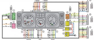
Electrical diagram VAZ-2107 carburetor
Electrical diagram of VAZ 2107, 21074 produced in 1988-2001 with generator 37.3701
- block headlights
- side direction indicators
- accumulator battery
- starter relay
- carburetor electro-pneumatic valve
- carburetor microswitch
- generator 37.3701
- gearmotors for headlight cleaners *
- Fan motor switch sensor
- engine cooling fan motor
- sound signals
- distributor
- spark plug
- starter
- coolant temperature gauge sensor
- engine compartment lamp
- low oil pressure warning sensor
- low brake fluid level indicator sensor
- windshield wiper motor
- carburetor electro-pneumatic valve control unit
- ignition coil
- headlight washer pump motor *
- windshield washer pump motor
- mounting block
- windshield wiper relay
- hazard warning and direction indicator relay
- brake light switch
- reverse light switch
- ignition relay
- ignition switch
- three lever switch
- hazard switch
- socket for portable lamp**
- heater fan switch
- additional resistor for the electric motor of the heater (stove)
- rear window heating indicator lamp
- low brake fluid level warning lamp
- signaling unit
- heater fan electric motor
- glove compartment lamp
- light switches on the front door pillars
- switches for warning lights of open front doors ***
- front door open warning lights ***
- connection block
- cigarette lighter
- watch
- instrument light switch
- diode for checking the serviceability of the low brake fluid level indicator lamp
- fuel level indicator
- fuel reserve indicator lamp
- speedometer
- turn signal indicator lamp
- carburetor choke indicator lamp
- battery charge indicator lamp
- carburetor choke warning switch
- instrument cluster
- econometrician
- light switches on the rear door pillars
- coolant temperature gauge
- tachometer
- parking brake indicator lamp ("handbrake")
- low oil pressure warning lamp
- high beam indicator lamp
- indicator lamp for turning on external lighting
- voltmeter
- parking brake indicator switch ("handbrake")
- outdoor light switch
- rear window heating switch with backlight
- rear fog light switch with on/off indicator *
- fog light circuit fuse
- lampshade ****
- tail lights
- level indicator and fuel reserve sensor
- connectors for connecting to the rear window heating element *
- license plate lights 2107
Wiring diagram VAZ-2107 carburetor - full view:
Troubleshooting algorithm
There is no need to think that charging is not happening for some very serious reason. Immediately check the condition of fuse F10, which is responsible for powering the excitation winding of the VAZ 2107 generator. But before doing this, it is better to make sure that the drive belt is intact and its tension is normal. But also pay attention to the fact that you cannot over-tighten it - there will be no recharging of the battery (provided that the regulator is operating in the intended mode), but the bearings will fail much faster.
If charging is not going well, the lamp, for example, burns at half intensity, then the fault must be looked for in the wiring. Namely, in the connections between the battery and the car body. Very often oxidation occurs, which prevents normal contact. Unscrew the nut, thoroughly clean the terminal and body surface, and then install the wire in place.
But if everything is fine with the switching, but charging still does not occur, you need to look further for the reason. And the first thing to suspect is the voltage regulator. With its help, the voltage at the generator output is stabilized. If this element fails, the battery overcharges or it does not charge well. Repair of this element is impossible, and the price in stores will be about 300 rubles. There are several options for regulators:
- A separate unit - installed on the body of a VAZ 2107 car.
- Combined with brushes - mounted directly in the generator.
How to check the regulator will be discussed in a separate article. If it is working properly, but charging still does not occur, or it is there, but it does not flow to the battery well, look for a fault in the brush assembly. It is quite possible that the wires that connect the brushes to the contacts have broken. But the most common thing is excessive wear or clogged brushes.
Somewhat less often, failure of the diode bridge or destruction of the stator or rotor windings occurs. To determine these breakdowns, you will need to completely disassemble the generator and carry out diagnostics using a tester and megger. Along the way, of course, it is best to replace the bearings in the VAZ 2107 generator.
Mounting block connection diagram
P1 — relay for turning on the heated rear window; P2 - relay for turning on the headlight cleaners and washer; P3 - relay for turning on sound signals; P4 - relay for switching on the electric motor of the engine cooling system fan; P5 - headlight high beam relay; P6 - low beam headlight relay; A - the order of conditional numbering of plugs in the mounting block blocks. The outer number with the letter “Ш” in the plug designation is the block number, and the inner number is the conventional number of the plug.
Generator repair
In this manual we will look in detail at the VAZ 2107 - generator repair. For repairs, you will need a bearing puller, a mandrel for pressing and knocking out bearings in the generator cover. So let's get started:
- Using a socket wrench, unscrew the nut securing the pulley and impeller, and use a screwdriver to hold the rotor from turning;
Unscrew the impeller fastening nut
- We pull the pulley off the shaft, then the fan impeller, take out the key, take out the spacer washers;
We remove the pulley, impeller and spacers
- We unhook the voltage regulator relay, first unscrew the fastening screws, and disconnect the wire block;
Unscrew the screws securing the relay
- We take out the voltage regulator along with the brush assembly from the housing;
We take out the regulator and brushes
- We unscrew the nuts securing the generator cover with a 10-mm socket and a ratchet, and remove the bolts;
Unscrew the nuts securing the cover
- We rest the cover against a block of wood, helping by hitting the shaft with a rubber hammer, knocking down the front cover;
Removing the front cover
- Remove the cover and take out the spacer bushing;
- Check the condition of the front ball bearing. To do this, hold the cover tightly, turn and rock the bearing itself (the inner ring of the ball bearing) with your fingers. If excessive play is detected or the bearing is broken, it should be replaced with a new one;
- To replace a faulty ball bearing, use a size 8 wrench to unscrew the nuts securing it;
Unscrew the nuts to remove the ball bearing
Attention: If the nuts do not unscrew, then it is necessary to cut off the riveted ends of the bolts. During assembly, we install new bolts, tighten their ends, then rivet them with a core.
- We take out the mounting bolts and washers securing the bearing;
We take out the bolts and washers
- We select a suitable mandrel (punch) and knock out the bearing;
Knock out the bearing
- We take two wooden blocks, rest the edges of the back cover against them, and use a drift made of soft metal to knock out the rotor. If the surfaces of the lids are suddenly damaged, treat them with an abrasive wheel;
We knock out the rotor
- We check the serviceability of the rear ball bearing using the method described in point 8;
- If replacement is required, remove it from the rotor using a puller;
Puller
- Using a 8-mm socket with an extension and a ratchet, unscrew the nuts securing the diode block (diode bridge) and the leads from the stator winding;
Unscrew the diode bridge
- We take out the bolts and pull out the stator from the cover;
- We check the integrity of the stator winding. If the winding is damaged by mechanical action (scuffs, broken wires), or from overheating (blackened, burnt), then we replace the stator winding or rewind it, if time and price permit;
Pull out the stator winding
- Using a ratchet head, remove the generator output nut along with a washer made of an insulating substance;
- Now we can remove the diode bridge itself;
We take out the diode bridge
- Using a Phillips screwdriver, unscrew the screw securing the capacitor and remove the capacitor. We remove the third bolt from the cover, which secures the rectifier unit.
Removing the third bolt
After completely disassembling the generator, we check the stator and rotor using a test lamp (watch the video). VAZ 2107 generator (repair and replacement) yourself is not such a difficult task, you no longer need the services of auto electricians. This will save you a lot of money.
Schemes of individual blocks of the seven
Power supply system
Power plant starting system
1 - starter; 2 - relay; 3 — ignition switch; 4 - battery
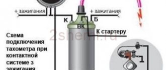
Ignition system
1 - generator; 2 — ignition switch; 3 - distributor; 4 - breaker; 5 — candles; 6 - coil; 7 - battery
Contactless ignition system
External and internal lighting
Windshield wipers and washers
1 — electric motors of the windshield wiper; 2 — washer motor; 3 — mounting block; 4 — ignition switch; 5 - washer switch
Cooling Fan
1 — fan electric motor; 2 - sensor; 3 — mounting block; 4 - ignition relay; 5 - ignition switch.
Wires for connecting electrical appliances
| Connection type | Section, mm 2 | Insulation color |
| Negative terminal of the battery - vehicle ground (body, engine) | 16 | Black |
| Starter positive terminal - battery | 16 | Red |
| Positive contact of the generator - plus battery | 6 | Black |
| Generator - black connector | 6 | Black |
| Terminal on the generator “30” – white MB block | 4 | Pink |
| Starter connector “50” – starter relay | 4 | Red |
| Starter Start Relay - Black Connector | 4 | Brown |
| Ignition switch relay - black connector | 4 | Blue |
| Ignition switch output “50” – blue connector | 4 | Red |
| Ignition switch connector “30” – green connector | 4 | Pink |
| Right headlight plug - ground | 2,5 | Black |
| Left headlight plug - blue connector | 2,5 | Green, gray |
| Generator output “15” – yellow connector | 2,5 | Orange |
| Right headlight connector - ground | 2,5 | Black |
| Left headlight connector - white connector | 2,5 | Green |
| Radiator fan - ground | 2,5 | Black |
| Radiator Fan - Red Connector | 2,5 | Blue |
| Ignition switch output “30/1” – ignition switch relay | 2,5 | Brown |
| Ignition switch contact “15” – single-pin connector | 2,5 | Blue |
| Right headlight - black connector | 2,5 | Grey |
| Ignition switch connector “INT” – black connector | 2,5 | Black |
| Six-pin block of the steering column switch - “ground” | 2,5 | Black |
| Two-pin block of the steering column switch - glove box illumination lamp | 1,5 | Black |
| Glove compartment light - cigarette lighter | 1,5 | Black |
| Cigarette lighter - blue block connector | 1,5 | Blue, red |
| Rear window defroster - white connector | 1,5 | Grey |
Battery charging circuit
The same scheme is used not only on the VAZ 2107; a similar one is used in any other car. The only difference is in the components - they are designed for different currents and operating modes. Charging circuit:
The circuit is not simple, it has a lot of elements that can fail. The contact may even break, causing the alternator to not charge the battery well. And all this affects your nerves - panic immediately begins.
1 - battery; 2 — Generator impeller; 3 - Protection diodes; 4 - Drive pulley; 5 - Rectifier diodes; 6 - Stator winding; 7 - Voltage regulator; 8 - Excitation winding; 9 - Filter capacitor; 10 - Fuse block; 11 - Indicator lamp on the dashboard; 12 - Voltmeter; 13 - Ignition switch relay; 14 - Ignition switch.
But there is no need to panic, it is enough just to diagnose the condition of all elements of the system. And even if you have an injector installed on a VAZ 2107, the car will be able to withstand the journey to the nearest service station or auto parts store. If the battery is in good condition, of course.
Car wiring diagram
1 – radiator fan drive motor; 2 – relay and fuse block (mounting block); idle speed sensor; 4 – engine control unit; 5 – potentiometer; 6 – set of spark plugs; 7 – ignition control unit; 8 – electronic crankshaft sensor; 9 – electric fuel pump; 10 – tachometer 2107; 11 – lamp for monitoring the health of electronic systems; 12 – ignition system control relay; 13 – speed sensor; 14 – diagnostic connector; 15 – set of injectors; 16 – adsorber solenoid valve; 17, 18, 19 – fuse block protecting the injection system circuits; 21 – electronic fuel pump control relay; 22 – electronic relay for controlling the intake pipe heating system; 23 – intake pipe heating system; 24 – fuse protecting the heater circuit; 25 – electronic oxygen level sensor; 26 – cooling system temperature control sensor; 27 – electronic air damper sensor; 28 – air temperature sensor; 29 – pressure control sensor.
How to check the generator
An initial performance check is carried out if the battery charging indicator light on the dashboard lights up while the engine is running. First check the belt tension. When pressing on the middle part of the belt sag with your thumb with force, the belt displacement should be in the range from 1.0 to 1.5 centimeters. With a larger displacement, the belt may slip and the dynamo will not provide the required charging current. Too much belt tension (less than 0.5 cm) leads to premature wear of the bearings. If the belt is very worn, it should be replaced.
Next, with the engine running, use a multimeter to measure the voltage on the battery. The multimeter probes are connected to the battery terminals. The voltage should be between 13.5 and 14.5 Volts. On a weak battery, the voltage can rise to 15 Volts, but no more. If the voltage is outside these limits, then repair is necessary. Before making this decision, you should check the voltages supplied to the generator terminals.
Fuse and relay diagram 2107
On newer “sevens” a block with 17 fuses and 6 relays is installed. VAZ 2107 fuses on the “new” unit protect the following electrical circuits and devices:
- Reversing lamps, heater fan, rear window defroster warning lamp and relay, rear wiper motor and rear washer pump.
- Electric motor for front wipers.
- Reserve socket.
- Reserve socket.
- Power supply for heated rear window.
- Clock, cigarette lighter, power socket “carrying”.
- Signal and radiator fan.
- Turn signal lamps in emergency mode.
- “Fog lights” and a relay that regulates the voltage of the on-board network.
- Instrument panel lamps.
- Brake light bulbs.
- Right high beam headlight.
- Left high beam headlight, high beam warning lamp.
- Side lights (rear right, front left), license plate and engine compartment lighting.
- Side lights (rear left, front right), glove compartment and cigarette lighter lamps.
- Low beam (right lamp).
- Low beam (left lamp).
The block relays perform the following functions:
- Heated rear window relay.
- Headlight cleaner and washer relay.
- Signal relay.
- Cooling system electric fan relay.
- High beam relay.
- Low beam relay.
The fuse block of the VAZ 2107 (injector) is no different from the block on the carburetor “seven”. Injection models are simply equipped with an additional relay and fuse box installed in the cabin under the glove compartment. The block includes three relays - the “main” relay, the fuel pump relay and the fan relay.
No charging: signs and reasons
If the voltage from the generator for some reason stops supplying the battery, it will be discharged in a few days . And in the event of a complete failure of the battery installation, you will have to provide the entire on-board network, including the ignition system, yourself. So she can work for no more than an hour.
Signs of no charge
Symptoms that the alternator is not charging the battery include:
- a constantly burning or intermittently turning on warning light on the dashboard;
- rapid battery discharge;
- reduction in the performance of individual electrical devices on the machine's on-board network.
Signal lamp
There is a special lamp on the dashboard of the “Seven” that indicates that the battery is not charging. If the generator circuit is operating in normal mode, the lamp lights only when the ignition is on until the power unit starts operating. After starting the engine it should go out . If it continues to light, most likely the battery is not charging.
The first sign of a lack of battery charging is a constantly burning red lamp in the form of a battery.
It also happens that the control lamp turns on periodically. This is a sign that voltage is either not supplied to the battery at all, or is supplied inconsistently.
Battery drains quickly
If the generator or its circuit malfunctions, the battery will not receive the voltage necessary to charge it. In addition, she will have to power part of the car’s electrical equipment, consuming her own electricity. In such a situation, the battery will quickly run out. You will be able to understand this when difficulties arise in the process of starting the engine. Receiving insufficient energy, the starter will sluggishly turn the crankshaft flywheel or only “click” the traction relay.
Reduced electrical performance
Some electrical appliances will also help you understand that the generator is not operating normally. If you suspect a malfunction in the operation of the generator set, you can, for example, start the engine, turn on the headlights (if they have conventional incandescent or halogen lamps) and see how they shine . If the generator malfunctions, their brightness will be an order of magnitude lower, because the lamps are also designed for a certain rated current. A decrease in performance may also be observed at the heater fan. It will spin the blades noticeably worse. When it is turned on, the light from the headlights will be even weaker.
Reasons for lack of charging
There are few reasons for the battery not charging. These include:
- violation of the integrity (break) of the drive belt;
- belt loosening;
- a break in the wiring of the electrical circuit of the generator or severe oxidation of the connecting terminals;
- rectifier malfunctions;
- voltage regulator failure;
- a break in the generator windings or a short circuit.
Belt break
Although the belt is designed for 50 thousand km, it can break even after several days of use. Especially if there are defects in the pulleys of the device itself, the crankshaft or the pump. In itself, a break in the generator drive belt is not dangerous for the engine, but only if this malfunction is detected immediately. And the point here is not so much the lack of charging, but the pump stopping. If it stops working, the engine will instantly overheat. And this is already fraught with burnout of the cylinder head gasket with all the ensuing consequences. So if the warning light comes on or other symptoms of alternator malfunction occur, the first thing to do is check to see if the drive belt is intact. To do this, you need to stop the engine, open the hood and perform a visual inspection of the generator set drive.
If the belt breaks, not only the generator stops working, but also the pump.
Loosening the belt
The drive belt must have a certain tension. When the tension is weakened, it will slip on the crankshaft pulley, not providing the number of rotations of the generator rotor that is necessary to generate current with the required parameters. A sign of a loose belt is a characteristic whistle, which most often occurs when air humidity increases. When the belt slips, the warning light usually does not come on, but in some cases it may turn on for a while or blink.
If the generator belt tension is weak, it may slip on the pulley.
Open circuit and terminal oxidation
The battery will not charge even if the integrity of the wires in the generator connection circuit is damaged. The battery charging circuit is quite simple: just one wire connects the positive terminal of the battery to terminal “30” of the generator set. It is through this that the voltage is supplied. The battery negative is connected to ground, to which the generator housing and the corresponding winding terminals are also connected. You just need to check for contact between the indicated points in the circuit.
Oxidation of the battery terminals, as well as their unreliable connection to the wire tips, can also significantly affect the current supply . You can check the condition of the terminals visually, but you cannot determine how the current flows by eye. It is better to once again clean and retighten all wire connections on the battery and generator.
When the battery terminals oxidize, the contact deteriorates and the charging current stops flowing.
Failure of the rectifier module
If the rectifier breaks down, no current will flow from the generator to the battery. The block itself is a board with six silicon diodes (3 positive and 3 negative). If at least one of them burns out, the rectifier will need to be replaced, since it cannot be repaired.
The rectifier is designed to convert alternating current into direct current
Regulator failure
A stabilizer malfunction is characterized by a change in the characteristics of the current supplied to the battery. In other words, the charging voltage is supplied to the battery, but it is higher or lower than required. The regulator also cannot be repaired and must be replaced if it fails.
The relay regulator functions as a voltage stabilizer
Malfunction of phase windings
If a break occurs in the windings, the generator stops performing its tasks. When an interturn short circuit occurs, the installation may behave differently. Typically, a sign of such a breakdown is a characteristic burning smell and a hum during operation. These two faults can only be diagnosed after removing the device from the car. Repairing a generator in the event of a break or short circuit involves replacing the burnt winding or stator assembly.
If there is a break or short circuit in the windings, the generator fails