The VAZ 2107 car is equipped with a dashboard, which is necessary for the driver to monitor traffic conditions and notice malfunctions in time. When driving a car, the driver is obliged to monitor not only the road surface, but also the condition of the main parts of his vehicle. These main parts include:
- movement speed;
- engine temperature;
- presence of fuel in the tank;
- amount of oil in the engine.
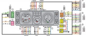
And these are just the main points that the driver monitors while the car is moving. This article will tell you about the main elements of the instrument panel, which will be discussed in the diagram below.
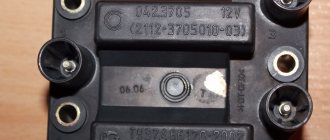
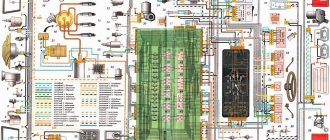
Scheme of VAZ 2107 carburetor produced 1988 - 2001 with generator 37.3701
The diagram of a VAZ 2107 carburetor is mounted on the principle of one wire. The negative current conductor is the body of the seven. Almost every wire laid inside the body of a VAZ 2107 serves as a positive conductor of electricity.
Front part of the diagram
| Position number on the VAZ 2107 carburetor diagram | Explanation of position |
| 1 | headlight |
| 2 | side turn lights; |
| 3 | battery |
| 4 | starter connection relay |
| 5 | carburetor electric valve |
| 6 | miniature carburetor switch |
| 7 | generator 37.3701 |
| 8 | headlight wiper motor |
| 9 | fan motor connection sensor |
| 10 | electric fan motor for engine cooling structure |
| 11 | signaling |
| 12 | ignition distributor |
| 13 | spark plugs |
| 14 | starter vaz 2107 |
| 15 | DUTOZH |
| 16 | engine compartment light |
| 17 | oil pressure indicator sensor |
| 18 | brake fluid level sensor |
| 19 | windshield wiper motor |
| 20 | carburetor electric valve control unit |
| 21 | ignition reel |
| 22 | electric motor for headlight washer pump |
| 23 | electric motor for windshield washer pump |
| 24 | fuse box VAZ 2107 |
| 25 | windshield wiper switch |
| 26 | hazard warning light and turn signal relay |
| 27 | brake light switch |
| 28 | rear light switch |
| 29 | ignition switch |
| 30 | ignition switch |
| 31 | three way switch |
| 32 | hazard warning light switch |
| 33 | electrical socket for carrying |
| 34 | heater fan switch |
Useful! VAZ 2107 fuse box
Back of the diagram
| Position number on the VAZ 2107 carburetor diagram | Explanation of position |
| 35 | additional resistor for electric heater motor |
| 36 | rear window heating indicator light |
| 37 | brake fluid level indicator light |
| 38 | signaling unit |
| 39 | electric heater fan motor |
| 40 | light bulb board |
| 41 | lamp switches on the front door pillars |
| 42 | front door open alarm lamp switches |
| 43 | front door open alarm lamps |
| 44 | terminal strip |
| 45 | cigarette lighter vaz 2107 |
| 46 | alarm |
| 47 | instrument light switch |
| 48 | diode for monitoring the health of the brake fluid level warning lamp |
| 49 | gasoline level indicator |
| 50 | gasoline reserve signal |
| 51 | speedometer |
| 52 | direction indicator connection signal light |
| 53 | carburetor throttle closing warning light |
| 54 | battery charging warning light |
| 55 | carburetor throttle warning switch |
| 56 | dashboard vaz 2107 |
| 57 | econometrician |
| 58 | light switches on the rear door pillars |
| 59 | antifreeze temperature indicator |
| 60 | tachometer |
| 61 | signal light for connecting the handbrake |
| 62 | low oil pressure warning light |
| 63 | signal light for connecting high beam headlights |
| 64 | signal light for connecting external lighting |
| 65 | voltmeter |
| 66 | handbrake warning switch |
| 67 | outside light switch |
| 68 | rear window heating switch with backlight |
| 69 | rear fog light switch with warning light |
| 70 | fog light circuit fuse |
| 71 | lamp |
| 72 | rear lights |
| 73 | gasoline level and quantity indicator sensor |
| 74 | terminal blocks for connecting to the rear window heating element |
| 75 | light bulbs numbers |
The sequence of conventional numbering of plugs in the blocks: a - headlights, headlight and windshield wipers, windshield wiper switches, carburetor electric valve control unit; b - fuse box and three-lever switch; c — emergency lights and turn signals; d — rear lights (numbering of pins in order from the edge of the board); d — hazard warning switch
Complete diagram of VAZ 2107 carburetor
In order to quickly find the necessary electrical circuits of specific devices and units, their local diagrams are located in additional subsections of this article.
Wiring diagram for connecting the adapter connector for checking the carburetor control unit
| Item no. | Explanation of the position on the diagram |
| 1 | ECU carburetor VAZ 2107 |
| 2 | voltmeter included in the adapter connector |
| 3 | pneumatic throttle |
| 4 | Ignition solenoid |
| 5 | view of the control unit plug connector |
Connection diagram for EPHH carburetor VAZ 2107
| Position number | Explanation of the position on the EPHH diagram of the VAZ 2107 carburetor |
| 1 | ecu for forced idle economizer (epkhh) VAZ 2107 |
| 2 | Ignition solenoid |
| 3 | small switch in the carburetor |
| 4 | pneumatic throttle |
| 5 | relay and fuse box |
| 6 | ignition switch. |
Helpful! Tightening torques for VAZ 2107
Removal and Replacement Guide
Changing the fuse box
Replacement of fuses and relays is necessary only if repair is impossible. To dismantle, follow these steps:
- The ground terminal is disconnected from the battery.
- The air filter housing is removed.
- All harnesses that fit the power supply unit are undocked.
- The shelf in the cabin under the dashboard and the glove compartment body are removed, and the harness with the connector is disconnected from the unit.
- Using a 10mm head, the block mount is unscrewed and the housing is removed along with the seal.
- The new device is installed in the reverse order.
Relays play an important role in the health of the system because they perform the operations to turn on or off the necessary functions in the car.
REFERENCE. The mounting blocks use two types of relays; they differ in design and operating principle:
- Electromagnetic component on and off relays are ordinary relays. Their contacts close and open when voltage is applied and removed.
- Specialized relays have a built-in compact electronic unit that turns certain components on and off.
To check the functionality of the relay, you must perform the following steps:
- The ground wire in the car is disconnected from the battery.
- The relay can be easily pulled out by hand.
- A visual inspection of the contacts is carried out, they are cleaned of oxidation, and the reliability of the pin fastenings is checked.
- Functionality testing is performed by applying 12V power to the winding using two pieces of wire.
- When power is supplied, the coil should operate, and the contacts should also close, which can be checked using a multimeter in the vertebrae or resistance measurement mode.
- The relay should be replaced with a new one if it is not working.
Pinout of fuse box 2107
In the photo, numbers from 1 to 6 indicate relays or connectors for their installation:
- Rear window defroster control.
- Control of windshield wipers and headlight washer motor (if equipped).
- Control of sound signals (a plug is installed instead of a relay).
- Connector for installing a fan motor control relay designed to cool the radiator (not used in new VAZ 2107 models).
- Control of high beam headlight bulbs.
- Control of low beam electric lamps.
The photo also shows components that perform various protection functions (from F1 to F17):
- F1 protects the circuits of: lamps in reversing lights; stove fan; heater (on indicator lamp and control relay), washer pump and rear window wiper.
- F2 protects windshield wipers.
- F3 is in reserve.
- F4 is in reserve.
- F5 protects the rear window heater.
- F6 - cigarette lighter circuit, connector for turning on a portable lamp, clock on the dashboard.
- F7 - cooling fan and signal fuse.
- F8 - control circuits for turn signals in emergency mode.
- F9 - protection of fog light circuits and generator voltage relays for a number of VAZ models.
- F10 protects the dashboard warning lights.
- F11 - circuits for turning on the stop lamps.
- F12 - right high beam headlight circuits.
- F13 - protection of the left high beam headlight and warning lamp.
- F14 - protection of the side light circuits of the headlights (front left and rear right), rear license plate light, engine compartment light.
- F15 - protection of the side light circuits of the headlights (front right and rear left), lighting of the cigarette lighter socket, glove compartment.
- F16 - right low beam headlight lamp.
- F17 - left low beam headlight lamp.
VAZ 2107 connection diagram
Electrical diagram for connecting the VAZ 2107 starter, model 35.3708
| Item no. | Explanation of the position on the VAZ 2107 starter connection diagram |
| 1 | generator VAZ 2107 |
| 2 | source of electricity |
| 3 | starter VAZ 2107 model 35.3708 |
| 4 | additional starter switch |
| 5 | mounting block |
| 6 | ignition switch |
Wiring diagram for outdoor lighting
| Position number | Explanation of the position on the external lighting diagram of the VAZ 2107 |
| 1 | side light bulbs in headlights |
| 2 | engine compartment lamp |
| 3 | mounting block vaz 2107 |
| 4 | ignition switch |
| 5 | instrument lighting designer |
| 6 | outdoor light switch |
| 7 | instrument cluster lamp |
| 8 | external lighting indicator lamp |
| 9 | side and fog lamps in the rear lights |
| 10 | license plate lights |
Sound signal connection diagram
| Item no. | Explanation of the position on the signal connection diagram |
| 1 | sound signals |
| 2 | mounting block VAZ 2107 |
| 3 | signaling switch (RZ); |
| 4 | horn switch |
Wiring diagram for connecting hazard warning lights and direction indicators
| Position number | Explanation of the position on the emergency signal diagram of the VAZ 2107 |
| 1 | turn signal lamps in headlights |
| 2 | side direction indicators |
| 3 | mounting block VAZ 2107 |
| 4 | ignition switch |
| 5 | hazard switch |
| 6 | hazard warning and direction indicator relay |
| 7 | turn signal lamps located in the rear lights |
| 8 | turn signal warning lamp located in the instrument cluster |
| 9 | turn switch |
Useful! Generator VAZ 2107
Wires for connecting electrical appliances
| Connection type | Section, mm 2 | Insulation color |
| Negative terminal of the battery - vehicle ground (body, engine) | 16 | Black |
| Starter positive terminal - battery | 16 | Red |
| Positive contact of the generator - plus battery | 6 | Black |
| Generator - black connector | 6 | Black |
| Terminal on the generator “30” – white MB block | 4 | Pink |
| Starter connector “50” – starter relay | 4 | Red |
| Starter Start Relay - Black Connector | 4 | Brown |
| Ignition switch relay - black connector | 4 | Blue |
| Ignition switch output “50” – blue connector | 4 | Red |
| Ignition switch connector “30” – green connector | 4 | Pink |
| Right headlight plug - ground | 2,5 | Black |
| Left headlight plug - blue connector | 2,5 | Green, gray |
| Generator output “15” – yellow connector | 2,5 | Orange |
| Right headlight connector - ground | 2,5 | Black |
| Left headlight connector - white connector | 2,5 | Green |
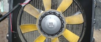
| Radiator fan - ground | 2,5 | Black |
| Radiator Fan - Red Connector | 2,5 | Blue |
| Ignition switch output “30/1” – ignition switch relay | 2,5 | Brown |
| Ignition switch contact “15” – single-pin connector | 2,5 | Blue |
| Right headlight - black connector | 2,5 | Grey |
| Ignition switch connector “INT” – black connector | 2,5 | Black |
| Six-pin block of the steering column switch - “ground” | 2,5 | Black |
| Two-pin block of the steering column switch - glove box illumination lamp | 1,5 | Black |
| Glove compartment light - cigarette lighter | 1,5 | Black |
| Cigarette lighter - blue block connector | 1,5 | Blue, red |
| Rear window defroster - white connector | 1,5 | Grey |
VAZ 2107 fuse diagram
Diagram of internal connections of the VAZ 2107 fuse box
| Here is an electrical diagram of the internal connections of the VAZ 2107 fuse mounting block. This diagram shows fuses, switching relays and plug connectors. The relays are shown with their internal electrical circuits. On the plugs, the number placed inside indicates the terminal number. The external designation Ш1, Ш2 and so on is the number of the plug connection. More comprehensive information is available on this page. |
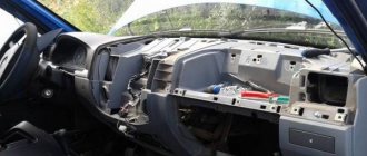
Removing the car dashboard
- Using a Phillips screwdriver, remove the three screws that secure the center console;
- remove the cover, the protrusion located at the bottom, remove the protrusion from the bracket;
- Using a nozzle, unscrew the five screws located in the console on the right and remove the screen;
- Disconnect the terminal with the (-) sign from the battery. If there is a radio receiver, you need to remove it, remove the plug from the shield;
- Disconnect the wires coming from the cigarette lighter, remove the cartridge;
- Using a narrow screwdriver, remove the handle from the levers;
- pull the handle towards the heating and fan switch;
- unscrew the two screws above the panel and the two located under it using a screwdriver;
- unscrew the screw located behind the panel;
- Also unscrew the two self-tapping screws securing the cover;
- disconnect the harness and wire connectors. To avoid confusion when installing the panels, you should mark the order in which they are connected;
- unscrew the fastening bolts;
- unscrew the two self-tapping screws, those that secure the bottom bracket using an 8 key;
- unscrew the self-tapping screw securing the light guide and remove it;
- Also unscrew the screws securing the heating unit;
- remove lamp sockets;
- after removing the external parts, remove the decorative insert;
- unscrew all nuts with a 21 key;
- hydrocorrector, remove its lamp;
- Unscrew the screws that are attached to the cross member on the left.
- Finally, the panel itself is removed. The panel is assembled accordingly in the reverse order.
In general, the repair work is quite doable even with your own hands, but before starting dismantling work, you need at least a pinout mapped on paper, otherwise it will be difficult: you will need to “trace” every wire and every connection that is on the “path” from devices to the power button.
Electrical ignition circuit for VAZ 2107
Ignition circuit for VAZ 2107 with a classic contact device
This electrical diagram shows the classic contact ignition system of the VAZ 2107. All devices included in this ignition circuit of the VAZ 2107 are shown with their own electrical block diagram. It allows you to better understand their operation and correctly connect these devices to the ignition electrical circuit. The VAZ 2107 ignition circuit starts from the fuse mounting block, passes through the ignition relay, ignition switch, ignition coil, ignition distributor and ends at the spark plugs.
| Item no. | Decoding the position on the ignition diagram 2107 |
| 1 | relay and fuse block |
| 2 | ignition switch |
| 3 | ignition switch |
| 4 | Ignition solenoid |
| 5 | ignition distributor |
| 6 | spark plugs |
Wiring diagram of a non-contact ignition system
| Item no. | Explanation of the position on the diagram of the contactless ignition system of the VAZ 2107 |
| 1 | ignition switch |
| 2 | ignition stick |
| 3 | mounting block for relays and fuses |
| 4 | Ignition solenoid |
| 5 | switch vaz 2107 |
| 6 | ignition distributor sensor |
| 7 | spark plugs |
LED panel lighting
The most popular tuning is the LED lighting of the VAZ 2107 instruments, which makes the torpedo attractive, especially at night.
To perform tuning, you will need to prepare:
- 10 light bulbs 3 V each;
- special train;
- a piece of wire from a molex connector;
- resistor with a resistance of 680 ohms.
Tidy with LED lighting
The procedure consists of three stages:
- First you need to prepare the LEDs by cutting off their heads. Then you need to cut the molex wire into 3 cm pieces and bend them in the shape of the letter “L”. The prepared wires need to be soldered in the places where the LEDs will be placed.
- The next step is trimming the LEDs. You need to form wires from the cut cable and use them to connect 4 LEDs into one circuit.
- The brightness is adjusted using the adjustment knob. You need to adjust the brightness in each of the two circuits containing 4 LEDs. You need to drive very carefully with this kind of lighting.
You can also highlight the arrows. The best way to do this is on the speedometer and tachometer.
VAZ 2107 wiring diagram
Electrical wiring diagram for the VAZ 2107 stove
| Item no. | Explanation of the position on the stove wiring diagram |
| 1 | relay and fuse block |
| 2 | ignition switch VAZ 2107 |
| 3 | heater electric motor switch |
| 4 | additional resistor |
| 5 | electric heater fan motor |
Brake warning lamp wiring diagram
| Item no. | Explanation of the position on the brake warning lamp diagram |
| 1 | brake fluid level meter |
| 2 | mounting block vaz 2107 |
| 3 | ignition switch |
| 4 | handbrake control relay |
| 5 | handbrake control switch |
| 6 | instrument cluster with handbrake control |
| 7 | checking the brake fluid level |
Wiring diagram (location of wiring harnesses) VAZ 2107 carburetor in the engine compartment
| Position number on the VAZ 2107 diagram | Explanation of the position on the wiring diagram | Article number |
| 1 | wiring (harness) of the right mudguard | 21050-3724016-72 |
| 2 | battery wiring harness | 21050-3724070-02 |
| 3 | battery wiring (harness) | 21044-3724080-10 |
| 4 | left mudguard wiring harness | 21070-3724017-02 |
| 5 | bundle of wires (wiring) of the ignition distributor | 21010-3707080-00 |
| 6 | high voltage wire | 21010-3707150-00 |
This wiring diagram is mounted on models VAZ-2107, VAZ-2107-01, VAZ-21074-01, VAZ-21074-02
Location of wiring harnesses (wiring diagram) VAZ 2107 injector in the engine compartment
| Position number on the VAZ diagram | Explanation of the position on the wiring diagram | Catalog number |
| 1 | Right mudguard wiring harness | 21073-3724016-00 |
| 2 | Ignition wiring (harness) | 21073-3724026-00 |
| 3 | Battery wiring harness | 21050-3724070-02 |
| 4 | Battery wiring (harness) | 21044-3724080-10 |
| 5 | Injector wiring harness | 21214-3724036-00 |
| 6 | Wiring (harness) of the left mudguard | 21073-3724017-00 |
| 7 | Ignition module wiring harness | 21214-3707080-10 |
This wiring diagram is installed on models VAZ-2107-20, VAZ-2107-21, VAZ-21074-21
Wiring layout for the VAZ 2107 body
| Position number on the VAZ diagram | Explanation of the position on the wiring diagram | VAZ catalog number |
| 1 | Fuel level sensor wiring harness | 21073-3724037-00 |
| 2 | Instrument panel wiring (harness) | 21070-3724030-41 |
| 3 | Additional wiring harness | 21044-3724100-00 |
| 4 | Rear wiring harness | 21050-3724210-03 |
| 5 | Ground wire for fuel level indicator sensor | 21030-3724220-00 |
| 6 | Ground harness (wiring) for license plate lights | 21050-3724214-00 |
| 7 | Ground wire | 21020-3724220-00 |
This wiring diagram is mounted on models VAZ-2107, VAZ-2107-01, VAZ-2107-20, VAZ-2107-21, VAZ-21074-01, VAZ-21074-02, VAZ-21074-21
Pointer indicators
Pointer indicators are divided into two types: large (speedometer, tachometer) and small, depending on the diameter of the dial. They are located symmetrically on both sides of the indicator lights. Let's look at their purpose:
- The speedometer is the main indicator located on the right side of the dashboard. Shows the current speed at which the vehicle is moving. Has 10 divisions, from 0 to 180 km/h. Each division is equal to 20 km/h;
- Fuel level sensor - located to the right of the speedometer, on top. Indicates the amount of gasoline in the gas tank. Has yellow and green divisions. If the arrow points to the yellow division, then there are less than five liters of fuel in the tank;
- Voltmeter - located under the fuel level sensor, and is used to determine the current strength in the vehicle system. It has 4 divisions, arranged in this order (from left to right) - red, yellow, green, red. If the arrow is on the left red division, then the charge level is low, if on yellow it is normal, on green it is excellent, and on the far right, also red, the current is too high;
- Tachometer – located to the left of the indicator lights. Indicates the number of revolutions of the crankshaft in 1 minute. Has 9 divisions, from 0 to 80 X 100 rpm. Each division is 1000 revolutions;
- Econometer - located to the left of the tachometer, on top. Indicates the most economical driving mode, depending on the current fuel consumption. It has 3 divisions, designated by colors: red, yellow, green, where red is increased consumption, yellow is moderate, and green, respectively, is minimum consumption;
- Coolant temperature sensor – located under the econometer. It indicates the temperature of antifreeze or antifreeze, and has 3 divisions. If the arrow points to a white line, it means the fluid temperature is low and the engine is not warmed up; if the arrow points to green, the temperature is normal, and the red line means the engine is overheating.
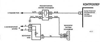
Electrical cooling circuit for VAZ 2107
| Position number | Explanation of the position on the VAZ 2107 cooling system diagram |
| 1 | cooling fan motor |
| 2 | motor switch sensor |
| 3 | relay and fuse block VAZ 2107 |
| 4 | ignition switch |
| 5 | ignition relay |
| 6 | motor start relay (P4) |
VAZ 2107 generator circuit
Electrical circuit of the generator model 37.3701
| Item no. | Explanation of the position on the generator circuit 2107 |
| 1 | power supply |
| 2 | generator |
| 3 | relay and fuse block VAZ 2107 |
| 4 | ignition switch |
| 5 | battery charge control |
| 6 | voltmeter |
Electrical circuit of the generator brand G-222
| Item no. | Explanation of the position on the generator circuit G 222 |
| 1 | battery |
| 2 | internal diagram of the VAZ 2107 generator carburetor |
| 3 | battery charge control stick |
| 4 | relay and fuse block |
| 5 | ignition switch VAZ 2107 |
| 6 | battery charge control |
| 7 | voltmeter |
VAZ 2107 headlight diagram
Wiring diagram of headlights and fog lights
| Item no. | Explanation of the position on the diagram of headlights and fog lights |
| 1 | headlight bulbs |
| 2 | mounting block VAZ 2107 |
| 3 | ignition switch |
| 4 | headlight switch |
| 5 | size switch |
| 6 | rear fog light switch |
| 7 | high beam headlight control |
| 8 | foglight control; |
| 9 | fog lights and tail lights |
| P5 | Relay for high beam headlights |
| P6 | low beam headlight switch |
Headlight adjustment diagram
| Item no. | Explanation of the position on the VAZ 2107 headlight adjustment diagram |
| 1 | horizontal light beam adjustment screw |
| 2 | headlight housing |
| 3 | terminal block |
| 4 | set screw |
| 5 | screw for adjusting the light beam in the vertical direction |
Electrical diagram of the VAZ 2107 panel
| Item no. | Explanation of the position on the panel diagram |
| 1 | oil pressure indicator sensor |
| 2 | antifreeze heat indicator sensor |
| 3 | oil pressure sensor |
| 4 | mounting block VAZ 2107 |
| 5 | sensor for level indicator and gasoline reserve |
| 6 | Gasoline level and reserve indicator |
| 7 | tachometer |
| 8 | antifreeze heat indicator |
| 9 | oil pressure gauge with control |
| 10 | ignition switch VAZ 2107 |
| 11 | pneumatic valve control unit |
| 12 | ignition coil. |
Instrument cluster connection block diagram (rear view)
| Position number | Explanation of the position on the wiring diagram of the VAZ 2107 dashboard |
| 1 | voltmeter |
| 2 | fuel level indicator with reserve warning lamp |
| 3 | instrument lighting lamps |
| 4 | speedometer |
| 5 | carburetor air damper warning lamp |
| 6 | turn signal indicator lamp |
| 7 | tachometer |
| 8 | econometer VAZ 2107 |
| 9 | coolant temperature gauge |
| 10 | parking brake warning lamp |
| 11 | oil pressure warning light |
| 12 | high beam warning lamp |
| 13 | side light indicator lamp |
| 14 | battery charge indicator lamp |
What does the panel consist of?
The panel consists of a large number of elements that are responsible for the operation of certain components of the VAZ 2107 car. The instrument panel is located in the car interior and is directly embedded in the dashboard on the driver’s side. The main elements are located under a special plastic transparent glass, which protects them from mechanical damage. The elements of the instrument panel include the following elements:
- Accumulator charging;
- speedometer;
- odometer;
- tachometer;
- motor temperature sensor;
- ECON – instantaneous fuel consumption indicator;
- additional signaling elements;
- resettable odometer;
- and 10 – fuel level in the gas tank and warning light.
Let's briefly look at the purposes of each of these elements.
Instrument distribution diagram on the control panel of a VAZ 2107 car
- Speedometer. The device located on the right side of the panel is called a speedometer. Serves as an informant for the driver about the speed of the vehicle. The scale has values from 0 to 180, which indicates the speed of the vehicle. There are two dials on the device that keep track of the distance traveled by the “seven”. One of them has the ability to adjust, but the bottom one does not.
- Tachometer. The device located on the left side serves to inform the owner about the crankshaft rotation speed in relation to a unit of time. Most drivers do not really understand the purpose of this element and rarely pay attention to it. But this element is very important, since it is a direct indicator of the quality of engine operation. The closer the arrow gets to the red mark, the more the motor is overloaded. And when it crosses the red line, the car’s movement should be stopped immediately, since the engine is operating in critical mode.
- ECON flow indicator. The indicator, located in the upper left corner of the instrument panel, performs the function of indicating the consumption of the fuel mixture in instantaneous time while the engine is running. When driving at speeds above 90 km/h, fuel consumption increases and the arrow moves to a yellow position. A very useful feature for the driver to be able to save fuel.
- Temperature indicator. Designed to indicate the motor temperature value. Above 100 degrees Celsius, the needle moves to the red mark, which indicates overheating.
- Fuel indicator. Using this indicator, drivers determine the amount of fuel in the tank, which is transmitted through an electronic sensor and level.
- Battery charge. Indicates how good the battery is; position on the red mark indicates the need to recharge.
Windshield wiper and washer diagram for VAZ 2107
Electrical circuit for switching on the windshield wiper and washer
| Item no. | Explanation of the position on the diagram of windshield wipers and washers 2107 |
| 1 | windshield washer motor |
| 2 | electric wiper motor |
| 3 | mounting block |
| 4 | ignition switch VAZ 2107 |
| 5 | wiper switch |
| 6 | wiper switch |
Electrical circuit diagram for turning on the headlight cleaners and washer
| Item no. | Explanation of the position on the diagram of headlight cleaners and washers 2107 |
| 1 | electric headlight wiper motors |
| 2 | electric headlight washer motor |
| 3 | mounting block VAZ 2107 |
| 4 | ignition switch |
| 5 | headlight washer switch in the three-lever switch (at the same time it is a windshield washer switch); |
| P2 | Relay for turning on the wipers and headlight washers |
Diagram of VAZ 2107 injector (VAZ 21073-40)
The VAZ 2107 differs from the VAZ-21073-40 in the configuration of a 1.7 liter engine with central gasoline injection. On these engines, instead of the functioning of the carburetor, a central injection unit is mounted on the intake pipe; it contains a nozzle that supplies fuel according to ECU commands
The electrical circuit of the electrical equipment of the VAZ-21073-40 differs from the VAZ 2107 in the addition of the central injection system harness, the wires of which connect the ECU to the sensors and actuators of the injection system. Three wires, from the injection system harness, through a separate block, are connected to the low-voltage input of the tachometer on the instrument panel, with a separate “SNESK ENGINE” display and to pin 15 of the ignition switch.
The electric motor 26 of the engine cooling system fan is connected by the injection system control controller 15. Therefore, the radiator does not have a sensor for connecting the electric fan motor.
Electrical diagram of VAZ-21073-40 central injector
| Position number | Explanation of the position on the VAZ 2107 injector diagram |
| 1 | electric gasoline pump with gasoline level sensor |
| 2 | central injector sprayer VAZ 2107 |
| 3 | oxygen concentration sensor |
| 4 | octane potentiometer |
| 5 | air heat meter |
| 6 | absolute pressure device |
| 7 | TPDZ |
| 8 | DTOZH |
| 9 | idle air control |
| 10 | diagnostic block |
| 11 | speed meter |
| 12 | canister purge throttle |
| 13 | spark plugs |
| 14 | VAZ 2107 ignition module |
| 15 | ECU block |
| 16 | intake pipe heater fuse |
| 17 | injection system fuse |
| 18 | injection system fuses |
| 19 | injection system fuses |
| 20 | DPKV |
| 21 | connection block to the instrument panel wiring harness |
| 22 | instrument panel with tachometer |
| 23 | display with control lamp “SNESK ENGINE”; |
| 24 | car ignition switch |
| 25 | fuse box VAZ 2107 injector |
| 26 | electric motor cooling fan |
| 27 | injection system ignition switch |
| 28 | connector for connecting an electric gasoline pump |
| 29 | intake pipe heater relay |
| 30 | intake pipe heater |
| P4 | relay for connecting the electric fan motor |
| A | to the “+” contact of the battery |
| IN | to pin “15” of the ignition switch |
Diagram of the engine control system VAZ 2107 injector
Electrical connection diagram for the VAZ 2107 injection engine control system
| Position number | Explanation of the position on the VAZ 2107 injector diagram |
| 1 | ECU contacts |
| 2 | Mass air flow sensor |
| 3 | DTOZH |
| 4 | DPKV |
| 5 | TPDZ |
| 6 | lambda probe VAZ 2107 injector |
| 7 | speed meter |
| 8 | ignition module |
| 9 | canister purge solenoid valve |
| 10 | electric fan switch |
| 11 | electric gasoline pump relay |
| 12 | main relyushka |
| 13 | fuse protecting the power circuit of the electric fuel pump |
| 14 | fuse protecting the power circuits of the main relay |
| 15 | fusible insert |
| 16 | fuse protecting the continuous power supply circuit of the computer |
| 17 | diode |
| 18 | empty control |
| X1 | diagnostic connector VAZ 2107 injector |
| X2 | connection block to the car electrical equipment system |
New power system
To understand why so many different electrical equipment are installed on the car, and what the electrical wiring unites, you need to understand the principle of operation of the new power system.
Advice: For general development, it’s a good idea to watch a video on the Internet that clearly explains the difference in the operation of these systems.
The main difference between an injection system and a carburetor system is as follows:
- The electric fuel pump constantly increases the pressure in the fuel line (in the carburetor version there is no pressure, and the pump itself is mechanical);
- The air-fuel mixture is formed directly in the cylinder (injection system), whereas on the “classic” it is formed in the carburetor;
- Electric injectors are responsible for injecting fuel into the cylinders (nozzles in the carburetor, and from there the air-fuel mixture enters the intake manifold and then into the cylinders);
- The timing of injection is determined by the ECM (in the carburetor, fuel is sucked in when the intake valve opens).
Schematic representation of the elements of an injection type fuel system
Differences in electrical wiring
The platform for creating the VAZ 21074 car was the VAZ 2107 model. And although the same 1.6-liter engine was installed on the “seventy-four,” the carburetor was replaced with an injector.
This entailed changes, as a result of which the electrical wiring of the VAZ 21074 to the injector differs from the standard carburetor version:
- Added wiring harness from controller to fuel frame;
- Added wires to the radiator area - for sensors and fan;
- Wiring for the electric fuel pump has appeared.
Detailed wiring diagram for VAZ 21074 injector
For reference: the fuel pump on the carburetor VAZ 2107 was of a mechanical type and was installed directly on the power unit. For safety reasons, the electric fuel pump was installed away from the engine compartment - in the rear of the car.
The material on our website VAZ 21093 wiring diagram: service features will give you more information on this issue.
New sensors
Since the injection system operates according to pre-compiled algorithms (firmware), to activate them, the electronic system requires readings of numerous vehicle operating parameters.
For this purpose, additional sensors were installed:
- mass air flow;
- oxygen concentration;
- throttle position;
- vehicle speed;
- crankshaft position;
- gravity valve in the fuel line;
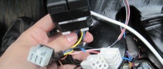
Mass air flow sensor terminal block
For reference: all sensors have connectors for connection. And the additional wiring has terminals for connection with the required pinout.
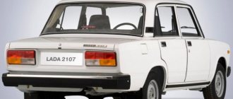
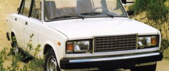
Models of Lada VAZ 2107
- VAZ-2107 is a small passenger car with a closed monocoque four-door sedan-type body. Carburetor engine with a displacement of 1.45 liters of the VAZ 2103-08 brand with toxicity standards R-83. The maximum speed of the car is 150 km/h. It had the “Standard” package and was produced for the domestic market.
- VAZ 2107-01 - was equipped with two types of carburetor engine: 2103-08 carburetor, 1.45 liters; 2103-07 carburetor, 1.45 l. On the 2103-07 engine, a valve cover made of antiphon was installed. It has a maximum speed of 150 km/h. It has the “Norma” package and was produced for the domestic and foreign markets.
- VAZ 2107-02 - differs from the head model VAZ-2107 by an engine with a displacement of 1.45 liters and a system with distributed gasoline injection. The controller of the following models 2104-1411020-00 (01, 02) was installed. Equipped with a VAZ 2104 engine. It has a maximum speed of 145 km/h. It has the same five-speed gearbox. Has the “Standard” package. Produced for the domestic and foreign markets.
- BA3-21073 - differs from the VAZ-2107 car in its engine with a displacement of 1.3 liters and a central fuel injection system.
- VAZ-21074 differs from the VAZ-2107 by an engine with a displacement of 1.6 liters. The passenger car was equipped with an engine of two models: 2106-13 - carburetor; 21067-10 - with distributed fuel injection. The injection engine was developed to meet Euro-2 toxicity standards.
Removing the standard instrument cluster
Removing the factory panel from a VAZ 2107 is quite simple; it is installed in a niche on special brackets and secured to them with screws. The procedure for dismantling the equipment is as follows:
- We disconnect the battery by disconnecting the negative wire from the corresponding terminal of the battery.
- Using a flat-head screwdriver, remove the handles from the control levers of the interior ventilation and heating system.
- We unscrew the locking nut of the daily counter reset handle with a wrench and remove it together with the washer.
- We take out the plug for the screw securing the decorative panel and unscrew it.
- With a slight turn, we take the assembly out of the niche and gain access to the instrument cluster.
- By hand, unscrew the union nut securing the speedometer cable to the device and undock it.
- We remove the tube from the econometer fitting and disconnect three electrical connectors.
After this, the decorative panel with the instrument cluster is completely removed from the niche and you can work with it on the table. As can be seen from the description presented, dismantling this device on a VAZ 2107 car is not particularly difficult and can be done by a car enthusiast independently.