Design and principle of operation of the ignition module
Some old-school motorists call the modules double-spark coils, which makes sense. After all, the coil is the predecessor of the ignition module in the technical evolutionary chain. The module is a paired design consisting of two pairs of windings (primary and secondary) and a switch that alternately switches low-voltage current from one coil to another. In some models of double-spark coils, the commutator is structurally located outside the block .
The operation of the module is controlled from an electronic unit that collects and analyzes information from various working components of the engine. The block, unlike the classic coil, has 4 sockets for connecting high voltage wires going to the spark plugs. The pulse occurs in pairs, first at terminals 1 and 4, then 2 and 3. That is, each of the built-in coils is responsible for the operation of two cylinders. A spark occurs simultaneously, as a pair.
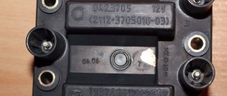
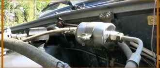
This is what one of the ignition module models looks like. The connector for connecting incoming wires is visible at the top.
At the input, the ignition module has a connector with four terminals. Usually most models have markings opposite them. Pulses from the Hall sensor alternately arrive at contacts A and B, serving as a signal to switch the commutator from one primary winding to another. C and D – ground and power supply (12 V), respectively.
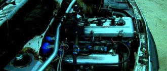
Location of the ignition module VAZ 2107
The ignition module is located on the front side of the cylinder block above the oil filter. It is secured to a specially designed metal bracket using four screws. It can be identified by the high-voltage wires coming out of the housing.
The ignition module is located on the front of the cylinder block above the oil filter
Electrical diagram of the VAZ 21074 car
A high-quality color diagram of the electrical equipment of the domestic passenger car VAZ-21074 is provided to help auto electricians and service stations. Model 21074 is an improved modification of the VAZ-2107. The “seventy-four” is equipped with the same 1.6-liter engine, but the carburetor is replaced with an injector. Some elements of the circuit are installed not on all, but only on part of the produced cars of this model. At the end of the article, fuses and the circuits they protect are shown. Schemes are enlarged by clicking.
When should you turn on the ignition?
The first thing you should know is that there are no regulations for this operation, since the ignition timing is set or adjusted only if necessary. It may be caused by the following reasons:
- You recently purchased a “Seven” on the secondary market and are trying to “bring it to mind.”
- After engine repair, accompanied by its disassembly.
- After unscrewing or removing the main ignition distributor (distributor), regardless of the reason why this was done.
- When switching from high-octane fuel to gasoline with a lower octane number and vice versa.
- After replacing the contact group or bearing in the distributor (in cars with an old ignition system).
- mechanical with contacts. switches;
- contactless;
- controlled by an electronic unit (ECU).
Note. On VAZ 2107 vehicles equipped with an electronically controlled injector, the reason for checking the spark generation system may be the flashing of the Check Engine display on the instrument panel. True, it behaves in a similar way when a dozen more malfunctions occur. So ignition problems must first be diagnosed by contacting a service station.
In the vast majority of cases, the sparking moment is set as a result of a violation of the settings after disassembling or repairing the engine. A separate issue is the transition to high-octane gasoline, which requires ignition with greater advance, for which adjustments are being made.
It is advisable to check the timely formation of a discharge on the electrodes of the spark plugs in cases where unstable engine operation is observed, popping noises are heard in the carburetor and exhaust pipe, accompanied by an increase in fuel consumption. If you have not yet discovered the “gluttony” of the car, then pay attention to the color of the smoke; with high gasoline consumption, it is black, as is the carbon deposits on the electrodes of the spark plugs.
Types of systems
For decades, until the release of the VAZ 2107 (from 1982 to 2012), it was equipped with three types of ignition systems:
The note. The first 2 grades were placed on the “seven” of the carburetor, the latter is represented by an injector.
In the mechanical embodiment, the contacts opened by the camshaft cam open the low voltage circuit, initiating the formation of a powerful pulse in the secondary coil winding. This discharge is directed to the fuel spark plug electrodes in the cylinder, where the piston rises to top dead center (TDC) and the compression stroke is completed.
The contactless circuit works on the same principle, only the Hall sensor signals an open circuit, and its switch implements this. Therefore, the ignition settings on the “seven” carburetor are almost identical. One more thing. These are nozzle machines that have a new system that not only has the contacts, but also the distributor and any moving parts. Here, the spark torque is determined by the ECU controller by focusing on the signals from different sensors.
Types of systems
For decades, while the VAZ 2107 model was produced (from 1982 to 2012), it was equipped with three types of ignition systems:
- mechanical with contacts - breakers;
- contactless;
- controlled by an electronic unit (ECU).
Contact ignition circuit installed in the first VAZ 2107 models
Note. The first 2 varieties were installed on the “seven” with a carburetor, the latter was introduced together with an injector.
In the mechanical version, the contacts opened by the cam of the distributor shaft break the low voltage circuit, initiating the formation of a powerful pulse in the secondary winding of the coil. This discharge is directed to the electrodes of the spark plug, which ignites the fuel in the cylinder where the piston has risen to top dead center (TDC) and the compression stroke is completed.
Scheme of non-contact ignition of the seven with a carburetor
The contactless circuit operates on the same principle, only the signal to break the circuit is supplied by the Hall sensor, and it is implemented by the switch. Therefore, setting the ignition on carburetor “sevens” is done almost identically. Another thing is cars with an injector, where a new system has been introduced that does not have not only contacts, but also a distributor and any moving parts. Here, the moment of spark formation is determined by the ECU controller, which is guided by the signals of various sensors.
Ignition system VAZ 2107 with injector
Preparatory stage
To set the ignition on a VAZ 2107 car, no special conditions are required; the operation can be done both in the garage and on the street, including in winter. For work, prepare the following set of tools:
- flat screwdriver;
- metal probe 0.35 mm thick;
- open-end wrench size 13 mm;
- a car light bulb designed for a voltage of 12 V with wires soldered to it;
- a wrench with a long handle designed to turn the crankshaft;
- key for unscrewing spark plugs.
Ignition tuning tool
Note. Instead of a special key to rotate the crankshaft, you can use a regular open-end wrench measuring 36 mm. If you don’t have such a key, then you will have to set the marks in the old proven way: by engaging 4th gear and raising the rear wheel, turn it manually, thereby turning the crankshaft.
Ideally, it is better to have in your arsenal a device for setting the ignition on a running engine - a strobe light. It is equipped with a lamp that flashes simultaneously with the moment of spark formation in the cylinder, which allows you to see the position of the notch on the crankshaft pulley at idle speed and clearly adjust the advance angle.
This is what a strobe looks like, which is convenient for adjusting ignition timing
Important point. The ignition is set in order to ensure that the spark appears in a timely manner and the engine starts, after which additional adjustments will be required. But the latter will not bring you the desired result when there is no compression in the cylinders or problems with the carburetor make themselves felt. If these faults are not eliminated, the engine operation will remain unstable, no matter how you configure the spark generation system.
Hence the conclusion: you can set the ignition correctly at any time, but to set it well - only on a working engine and carburetor.
Tuning on carburetor modifications of the VAZ 2107
All old textbooks on servicing classic Zhiguli models describe a method for setting the moment of spark formation using a light bulb, although experienced motorists can easily do without it. You will understand why this happens as you read this material, but for beginners it will be useful to familiarize yourself with the old proven technique.
To correctly set the ignition of the “seven”, you need to ensure that the following conditions are met simultaneously:
- the notch on the crankshaft pulley is opposite the long mark on the timing cover;
- in this case, the round mark marked on the camshaft chain drive gear coincides with the boss on its body;
- the piston of the 4th cylinder has completed the compression stroke and is at top dead center;
- the contacts inside the distributor are open;
- The movable contact of the slider faces the fixed contact on the distributor cover, where the wire from the spark plug of the 4th cylinder is connected.
Note. On non-contact systems, at this moment the Hall sensor sends a signal to the switch to break the low voltage electrical circuit, which leads to the appearance of a high voltage pulse on the wire leading to the spark plug of the 4th cylinder.
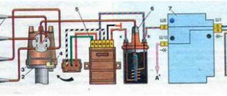
The diagram shows what happens in the cylinders when the marks are aligned
The light bulb is used to control the ignition timing, for which it must be connected with one wire to the “K” contact of the high-voltage coil, and with the second to the vehicle ground. You should know that at the same moment the piston of the first cylinder is also in the TDC position, only there the air-fuel mixture is not compressed, but exhaust gases are released after its combustion. This is why ignorant car enthusiasts often confuse the first cylinder with the fourth when installing the ignition.
Layout of marks on the timing cover
When the above actions occur simultaneously, a spark discharge occurs on the electrodes of the spark plug of the 4th cylinder, as evidenced by the flash of the connected light bulb. To achieve these conditions and set the ignition correctly, follow the instructions:
The marks must be aligned by turning the crankshaft with a wrench
Note. The instructions imply that before starting work the distributor was removed from the engine without aligning the marks.
The ignition is considered to be set correctly if, after installing the distributor cap and connecting the wires, you manage to start the engine, and then you need to adjust the timing. The non-contact system is installed in the same way, with the exception of checking the gap in the contact group due to its absence.
The mark on the camshaft gear is aligned with the boss on the body
Important point. In most cases, the ignition is set without removing the valve cover, which is why the position of the mark on the gear is not visible. You have done everything according to the instructions, but the engine does not start. This means that a spark is supplied to the 4th cylinder during the exhaust stroke, and compression at this moment occurs in the first cylinder. The problem can be solved simply:
- remove the distributor cover;
- unscrew the nut securing it;
- pull the distributor out of the socket, turn the slider exactly 180° and insert the element back;
- Press the distributor skirt with the nut and install the cover.
Advice. If the engine does not start after these steps, but begins to show signs of life, then the problem lies not in the ignition setting, but in a malfunction of one of the system elements.
Photo instructions for setting up
First of all, the marks on the pulley and timing cover are aligned
The distributor is inserted into the hole so that the slider points to cylinder 4
The distributor skirt is pressed against the block with a 13 mm nut
The gap is checked with a feeler gauge with the contacts open. The gap is corrected by unscrewing the 2 screws securing the contact group.
The light will light up when a spark appears
Contactless (electronic) ignition, carburetor
Many car owners are switching to a more accurate (electronic) type of ignition. To adjust the device yourself, you need to have skills in working with the electrical part of a car. If you do not have sufficient knowledge, entrust the work to experienced specialists.
Prepare the instrument for tuning. You will need keys (for “eight”, “ten” and “thirteen”), a Phillips screwdriver, a drill and a pair of self-tapping screws.
Pre-install the contactless system itself, consisting of the following elements:
- Trambler. Start by replacing the distributor by lifting the cover of the latter (this is how you gain access to the “slider”). Place the slider in a position that can be easily adjusted during installation. It is desirable that the notch be on the block opposite the middle mark of the device scale.
Use a “thirteen” wrench to tighten the fastening nut, and then dismantle the assembly. Now disconnect the central wire connecting the coil and the distributor. Mount the non-contact type sensor and adjust the slider taking into account the previously made mark. Align the distributor body along the notches. Replace the cover and return the wires to their place.
- Coil. In the next step, move on to the ignition coil. Take the eight key and twist the wires that are connected to the device. Now use the key to “ten” to push the assembly away from the car body.
Install the new coil taking into account the position of contacts “B” and “K”.
Fix the coil and connect the discarded and new wires to the contact group. Pay attention to the colors of the latter (as a rule, they are identical for the old and new devices). Connect the brown wire to terminal “K” and the blue wire to “B”. Now connect the center wire.
- Switch. Start by choosing a location for this node. In the "seven" the best point for installation is between the headlight on the left side and the washer. In this area there is a flat area on which the device is placed. To begin, lean the switch and mark the mounting locations. After this, screw in the screws. Do not rush to tighten the second fastener - place a black wire under it.
As soon as the described work is completed, check the quality of the connection of the wiring elements and start the engine. The next stage is installing the ignition of the VAZ-2107, which will be discussed below.
Ignition adjustment in static position:
- Find a strobe light. If this is not the case, do the work by ear.
- Loosen the nut holding the ignition coil.
- Start the engine and warm it up.
- Rotate the distributor housing left and right.
- Command your assistant to watch the speed (they should be at 2000 rpm).
- Listen to the engine noise. Try to catch the moments when there are “dips” or changes in rotation speed.
- Achieve a situation where the engine runs smoothly and produces the highest speed. In this case, the work should be as rhythmic as possible.
- Tighten the distributor nut and operate the car.
Setting the ignition timing of the VAZ-2107 in motion:
- Warm up the engine to a temperature of 80-95 degrees Celsius.
- Accelerate to a speed of 40-45 km/h, then move the gearbox selector to the fourth speed position.
- Step on the gas and listen to the engine. If the ignition is set correctly, detonation appears, and after a while the engine speed increases. If you hear a clear knocking of the valves, turn the distributor as the clock hand rotates by about 1-1.5 degrees.
- Perform the manipulations described above until the extraneous sound disappears completely.
- If the speed decreases sharply after pressing the gas, turn the distributor to the same angle, but in the opposite direction.
Remember that adjusting the advance angle may not be enough - often the carburetor itself needs to be adjusted. To do this, find a couple of screws. With one of them you regulate quality, and with the other you regulate quantity. Also clean the carburetor from time to time.
As can be seen from the described technique, setting up electronic ignition on the “seven” is not difficult. At the same time, you can count on serious savings, because at the service station this service will cost a considerable amount.
How to set the ignition on a VAZ 2107 with an injector?
The ignition system of the “Seven” with direct fuel injection operates under the control of an ECU that receives signals from the following sensors:
- crankshaft position;
- air flow;
- throttle position;
- lambda probe.
Multimeter for checking the ignition module
Based on the readings of these sensors, the controller itself determines the moment of spark formation, so the system is not configured in the usual sense. If any problems occur, the driver can only independently check the functionality of the ignition module, to which the high voltage wires from the cylinders are connected. To do this, you need to take a multimeter (ohmmeter) and perform the following steps:
- Disconnect all wires from the module.
- Set the maximum measurement value on the multimeter to 20 kOhm.
- Measure the resistance between the following pairs of terminals: 1 and 4, 2 and 3.
- If the measurement results fall outside the range of 3.6-4 kOhm, then the module is faulty and must be replaced.
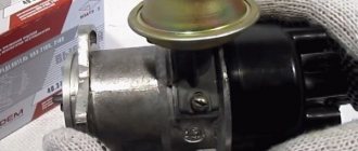
The seven with an injector has an ignition module, which you can check yourself
The principle of operation of the VAZ 2107 injection engine
The injection system's operating methods are fundamentally different from the operating principles of the carburetor system, in which the air-fuel mixture is prepared in the carburetor chamber. In the VAZ 2107 injection engine, the fuel mixture is injected directly into the cylinders. For this, it received the name “distributed injection system”.
Injection systems are characterized by their operating principle and the presence of different numbers of injectors. The “seven” is equipped with a separate injection system with 4 nozzles. That is, injection occurs in each cylinder, which is controlled by a microcontroller of the electronic engine control unit. Using special-purpose sensors, information about the operating mode, gas pedal position and other important parameters is read. Based on this, there is a controlled flow of fuel into the cylinders.
Photo of ECU VAZ 2107
Not only the quantitative proportionality of fuel and air entering the engine combustion chamber, but also control over the creation of a spark on the spark plugs depends on the electronic control unit (ECU).
General electrical circuit VAZ-2111
- Block lights;
- Sound signal;
- Engine cooling fan electric motor;
- Starter VAZ-2111;
- Accumulator battery;
- Generator;
- Reversing light switch;
- Electric drive for locking the right front door lock;
- Power window relay;
- Starter activation relay;
- Heater motor;
- Micromotor-reducer for heater damper drive;
- Windshield washer motor;
- Washer fluid level sensor;
- Electric drive for locking the left front door lock;
- Right front door power window switch;
- Electric trunk lock;
- Additional resistor for heater fan motor;
- Windshield wiper gear motor;
- Left front door power window switch;
- Electric power window of the right front door;
- Door lock system control unit;
- Outdoor lighting switch;
- Brake fluid level sensor;
- Electric window lifter of the left front door;
- Indicator lamp for turning on the fog light;
- Fog light switch;
- Instrument cluster;
- Rear window heating indicator lamp;
- Rear window heating switch;
- Understeering's shifter;
- Fog light relay;
- Ignition switch;
- Mounting block;
- Illumination lamp for heater control levers;
- Hazard switch;
- Automatic heater control system controller;
- Glove compartment lamp;
- Glove compartment lamp switch;
- Cigarette lighter;
- On-board control system display unit;
- Ashtray lighting lamp;
- Socket for portable lamp;
- Instrument lighting switch;
- Electric drive for locking the right rear door;
- Right rear door power window switch;
- Watch VAZ-2111;
- Electric window lift of the right rear door;
- Brake light switch;
- Electric window lifter of the left rear door;
- Left rear door power window switch;
- Electric drive for locking the left rear door;
- Side direction indicators;
- Parking brake warning lamp switch;
- Luggage compartment lighting;
- Individual lighting lamp;
- Interior lighting;
- Heating system temperature sensor;
- Switches in the front door pillars;
- Switches in the rear door pillars;
- Exterior tail lights;
- Interior tail lights;
- License plate lights;
- Rear window wiper motor;
- Rear window washer motor;
A — Pads for connecting the right front speaker; B — Pads for connecting audio equipment; B - 110: Blocks for connecting the rear window washer motor; G — Pads for connecting the left front speaker; D — Block for connecting the injection system wiring harness; E - Connector for diagnosing electric power steering; Ж - Connector for diagnosing the automatic heater control system; 3 — Pads for connecting the right rear speaker; I — Pads for connecting the left rear speaker; K - socket for connecting the on-board computer; L - to the electric trunk lock; M — Blocks for connecting additional brake signals; H - to the rear window heating element.
Disadvantages of injection models of the VAZ 2107 engine
Of course, as usual, in addition to the advantages of the injection “seven”, there are also negative aspects, which consist in the following situations:
• Problematic access to some components due to the location of the engine and other mechanisms under the hood in the same format as in older models. Although at the same time, the system providing fuel injection is reliable and does not require frequent maintenance during operation.
Photo of VAZ 2107 under the hood
• The injection VAZ 2107 is equipped with a catalyst, which is very easy to damage when driving on a bad road with large bumps and obstacles. In such cases, of course, you need to be careful when driving on problematic roads.
Photo of VAZ 2107 catalyst
• The presence of an injection engine increases the requirements for fuel quality, in contrast to the carburetor version. If you use low-quality gasoline, you cannot avoid clogging the fuel system. This leads to unplanned vehicle maintenance.
• If the injection system breaks down, it is not possible to repair it yourself in a garage. Here you only need to contact professionals at a specialized service station.
Fuse and relay box
The VAZ-2111 relay and fuse mounting block is located on the left side of the steering column in the instrument panel. To access the unit, press the latch switch and lower the unit down.
K1 - lamp health monitoring relay;
K2 - windshield wiper relay;
KZ - relay-interrupter for direction indicators and hazard warning lights;
What are the advantages of VAZ 2107 injection models?
• The VAZ 2107 injection engine consumes less fuel. At the same time, it is more powerful than a carburetor engine with the same volume. This is achieved through the optimal formation of the qualitative and quantitative composition of the fuel mixture. Accordingly, the efficiency of an injection engine is higher than that of a carburetor.
• Thanks to electronic speed control, the engine runs more reliably at idle, stalls less when starting, and starts well at low ambient temperatures.
• Compared to a carburetor engine, an injection engine does not require frequent adjustments to the ignition and fuel supply systems.
• The air-fuel mixture that enters the cylinders has the most favorable composition. And the existing catalyst controls the minimum amount of harmful exhaust gases. This plays a big role in preserving the environment and taking care of health.
• There is no need to manually adjust the mechanism, since this is done by the hydraulic chain tensioner and hydraulic valve clearance compensators. They also guarantee less noise (noise insulation) when the engine is running.
• Torque graphics are “smooth”, a larger rpm range allows high torque to be achieved.
WORTH NOTICE! On an engine with an injection system, it is possible to install gas-cylinder equipment not only of the 2nd, but also of the 4th generation. This is a more modern and attractive option, since the installation of the 4th generation of gas equipment provides greater savings and reduces the occurrence of “pops” in the engine to zero.
Diagnostics of malfunctions of the ignition module of injection VAZ 2107
The ignition of the injection VAZ 2107 is completely electronic and is considered quite reliable. However, problems can arise with it too. The module plays an important role in this.
Signs of a malfunctioning ignition module
Symptoms of a faulty module include:
- the Check engine warning light on the dashboard lights up;
- floating idle speed;
- engine tripping;
- dips and jerks during acceleration;
- change in sound and color of exhaust;
- increased fuel consumption.
However, these signs can also appear in case of other malfunctions - for example, in case of problems with the fuel system, as well as in case of failure of some sensors (oxygen, mass air flow, detonation, crankshaft position, etc.). If the engine starts to operate incorrectly, the electronic controller puts it into emergency mode, using all available resources. Therefore, when the engine operation changes, fuel consumption increases.
In such cases, you should first of all pay attention to the controller, read information from it and decipher the error code that has occurred. To do this, you will need a special electronic tester, available at almost any service station. If the ignition module fails, error codes in engine operation may be as follows:
- P 3000 - no sparking in the cylinders (for each cylinder the code may look like P 3001, P 3002, P 3003, P 3004);
- P 0351 - break in the winding or windings of the coil responsible for cylinders 1–4;
- P 0352 - a break in the winding or windings of the coil responsible for 2–3 cylinders.
At the same time, the controller can produce similar errors in the event of a malfunction (break, breakdown) of high-voltage wires and spark plugs. Therefore, before diagnosing the module, you should check the high voltage wires and spark plugs.
Main malfunctions of the ignition module
The main malfunctions of the VAZ 2107 ignition module include:
- a break or short to ground in the wiring coming from the controller;
- lack of contact in the connector;
- short circuit of the device windings to ground;
- break in the module windings.
Practical recommendations for working with the ignition module
The ignition module is one of those mechanisms in which it is quite difficult to determine the presence of malfunctions. They pay attention to it when serious deviations in the operation of the car are observed. If the VAZ 2107 engine does not start immediately, it is recommended to adjust the ignition, and if the engine is running unevenly, a proper check is required. The main thing here is not to forget that the ignition module of an injection engine is a system that, using coils, generates electrical energy to generate a spark and further start the vehicle.
Possible causes of failure
The weak point of the ignition coils and modules is the secondary winding, which generates a high voltage pulse. A coil break or breakdown may occur in it. The following factors lead to this phenomenon:
- use of low-quality or unsuitable candles;
- operation with non-functioning high voltage wires;
- frequent attempts to check the spark.
The high-voltage pulse arising in the secondary winding must be realized (spent). If this does not happen (if the integrity of a high voltage wire is broken, for example), a high-energy electrical pulse seeks an outlet. He will find it, with a high degree of probability, in the thin secondary winding.
Often, a module malfunction occurs when the integrity of poor-quality factory soldering of wires going to the switch elements is violated. This happens from vibration. Also, the cause of non-working coils can be a banal contact failure in the incoming connector. Another factor leading to a malfunction of the ignition unit is often moisture that gets on the device during washing or driving in unusual conditions.
First signs of trouble
The main signs of ignition coil failure are lack of ignition. If it is a single device with a distributor, then in all cylinders; if it is a double or single device, then in those served by it. The absence of a spark is not necessarily a 100% sign of a faulty coil. Perhaps the limiting resistor has burned out, the spark plug is faulty, the high-voltage wire has broken, or there is a malfunction in the ignition system. A comprehensive fault diagnosis is required.
Visual signs that the ignition coil is not working:
- the presence of “breakdown tracks”, oxides on the coil;
- change in dielectric color;
- burning of contacts and connectors;
- traces of overheating on the body;
- increased pollution.
Let's talk in more detail about these and other points indicating that the ignition coil of the VAZ 2106 is in a faulty state.
Presence of interruption tracks in the ignition coil
Let's figure out why the ignition coil breaks. Firstly, over time, as a result of high temperature changes, the dielectric insulation cracks, and salty moisture, which is a conductor, can enter microcracks.
The photo shows a common malfunction - breakdown of the ignition coil of a VAZ 2106
For voltages of more than 15,000 volts generated in the secondary winding, even pure undistilled water acts as a conductor. Secondly, during operation, the physical properties of the dielectric and rubber insulation of the tips of high-voltage wires, especially those of dubious production, change.
High-voltage breakdown can be caused by the installation of non-standard high-voltage wires in which there is no distributed current-limiting resistance. A breakdown can occur as a result of severe contamination or waterlogging. Even in the event of a single breakdown, irreversible changes occur in the structure; further operation is not recommended.
Burning of contacts and connectors of the ignition coil of a VAZ 2106
The big disadvantage, the disadvantage of CG, is the sparking process, which cannot be eliminated in any way. However, significant minimization of sparking can be achieved by connecting a capacitor. Yes, and be sure to set the correct gap.
Experts say that if you increase the gap above standard values, you can get rid of sparking. In other words, if the distributor contacts are burning, increasing the gap will be the optimal measure to eliminate the problem. However, this also has its drawbacks. In particular, the angle decreases, which leads to a decrease in the additional current voltage.
Traces of overheating on the ignition coil body of a VAZ 2106
Another sign by which you can determine the malfunction of the ignition coil of the VAZ Six is the presence of traces of overheating on the short circuit housing. The photo shows what they look like:
This is what signs of overheating look like on the ignition coil housing
Checking the ignition module
Checking the ignition module for functionality is carried out in the following ways:
Replacing the ignition module with a known good one
1. The easiest way is to connect a known working module. In this case, the devices must be completely identical, the high-voltage wires are in good condition, and the reliability of the contacts has been checked.
Checking the contacts on the ignition module
2. Moving the module, which allows you to identify unreliable contacts. To do this, move the wire block and the module itself. If during exposure the engine reacts by changing its operation, then the cause of the problem lies in poor contact.
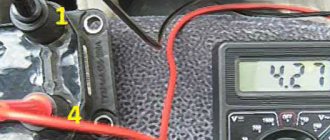
Measuring resistance at the terminals of the ignition module
3. Resistance measurement. To do this, you will need a tester switched to ohmmeter mode. Measurements are carried out on the paired terminals of the module between cylinders 1 and 4, as well as cylinders 2 and 3. The resistance value should be the same and approach 5.4 kOhm.
Checking the ignition module using a tester
4. Check the voltage with a tester. One probe of the device is applied to contact A of the block, the second to ground. After turning on the ignition, take readings from the device. If the wire is in good condition, it will show a voltage of 12 V; if it is missing, check the fuse protecting the ignition module. Then check the continuity of the circuit with a 12 V test lamp. Apply one end of the wire to contact A and rotate the starter. If the lamp does not blink, the circuit is broken. The procedure is repeated in a similar way with other contacts.
Diagnostics of the ignition module with professional equipment
5. Diagnostics at a service station by connecting a computer with special software to the computer. Malfunctions are detected in the form of errors indicated by an alphanumeric code, after which a more in-depth diagnosis of the malfunction is carried out to make a decision - repair the ignition module or replace it. A similar check is carried out at a specialized service station using an oscilloscope.
How to check the ignition coil of a VAZ-2109 yourself
First of all, it is necessary to point out that no matter what type of power unit (carburetor or injector) your car is equipped with, in any case, it has a distributor ignition system. Its advantage is its low cost. The disadvantage is the comparatively low durability of the units.
In this article we will talk about how to properly check the ignition coil on a VAZ-2109 car with your own hands.
Device
The ignition coil itself is designed to supply electricity to the spark plugs. Their cores produce a spark that ignites a mixture of air and fuel. In other words, it is actually an ordinary transformer operating in pulse mode. It converts the supplied 12 volts into 20 thousand. The transmission of the discharge is ensured by wires; their breakage also occasionally causes failure.
The coil itself consists of two windings:
- primary;
- secondary.
Symptoms of malfunction
As practice shows, the spark in a carburetor power plant very often disappears suddenly. However, having the necessary experience and knowledge, it is possible to identify the problem in advance.
Approximately half a thousand kilometers before the coil finally breaks down, problems arise with starting the engine when cold. It is usually possible to move off only after several minutes of warming up. The engine starts reluctantly. Moreover, most car enthusiasts are sure that the fault lies in the idle system.
This nuisance is often combined with unstable operation of the unit at low speeds. However, this lasts very little time - no more than half a minute, and therefore many simply do not notice the problem.
Another fairly clear signal is that the engine starts running when cold with the gas pedal pressed. The syndrome is eliminated in 5 seconds or even faster. If you press the pedal again, everything will work as it should.
When accelerating or changing gears, the following may occur:
- impetuosity of movement;
- vibration;
- decrease in dynamic performance.
However, in most cases, car owners pay attention to the ignition coil only when the spark completely disappears - that is, the car stops starting at all.
Verification procedure
If you detect one or more signs of “dying” of the coil or if it is impossible to start the engine, you should definitely check its performance. This is necessary in order to find out what nature of the breakdown occurred, and, therefore, begin to eliminate it.
Can this be done without instruments? Unfortunately no. Unless you immediately replace the coil with a known good one. At the very least, a regular multimeter will suffice. Such a tester must be kept in the car - its cost is almost symbolic.
In general, verification is relatively easy. It is enough to follow the steps described below, and even a completely inexperienced car enthusiast can handle it.
First of all, you need to inspect the ignition unit itself. If the engine does not start at all, then you need to find out if there is a spark. You need to do this:
- disconnect the main wire from the distributor (located in the center);
- connect a candle to it;
- holding it with pliers, apply it to the motor housing or to the breaker;
- turn on the ignition.
If there is no spark, there is only one conclusion - failure in the coil. Next, you need to find out whether electricity is supplied to it.
The check is carried out with a multimeter. One of its probes is applied to terminal “B” on the coil, the second to ground. If there is no voltage after turning on the ignition, the fault is looked for directly in the lock.
In addition, it is also possible to power the coil using an emergency circuit. Here the wire from the positive terminal of the battery is connected to contact “B”. In this situation, you can be absolutely sure that voltage is supplied. However, when these actions did not lead to a spark, you will have to test the primary winding for integrity.
- the wiring located on its sides is disconnected (they are low-voltage);
- the multimeter is set to Ohms and the resistance is measured;
- The secondary winding is also ringed in the same way.
Coil resistance measurement
It is important to note that this procedure cannot be performed without an ohmmeter or tester. The procedure is as follows:
- the car is de-energized (by disconnecting the negative cable from the battery);
- completely remove all wires from the coil;
- measurements are taken on the primary winding (the probes are applied to two low-voltage terminals, installed as we remember - along the edges);
- to avoid distortion of readings, it is necessary to thoroughly clean the outputs from dirt and oxides;
- It is better to write down the results.
Next, measure the resistance on the secondary winding with a tester. Here one probe is combined with the “B” contact, and the second with a high-voltage cable.
And finally, all that remains is to find out what the ground resistance is. To do this, one wire of the multimeter is applied to it, and with the second you need to touch three contacts in turn:
- two low-voltage;
- one high-voltage one (it is in the center of the coil).
If nothing happened to it, then in all three cases the tested resistance level will be within 50 Ohms.
Depending on the type of coil, the normal readings in Ohms will be as follows:
- at primary – 0.43 +/- 0.04;
- on the secondary – 4.08 +/- 0.40.
- 0,42 +/- 0,05;
- 5,00 +/- 1,00.
If nothing happened to the distributor, you will need to inspect the switch module - this can be done using a light bulb.
It will not be possible to check it qualitatively, since a special stand is used for this in car repair shops. But a light bulb (12-volt) will confirm that the impulse controlling the spark is being received.
To do this, remove the wire from the “K” connector from the coil itself and connect the lamp itself into the circuit in series (at break). When the starter starts working, it should blink - this indicates that the switch is working. Otherwise, it will need to be replaced with a functional one.
Ignition module wiring checks
Procedure:
- Disconnect the block with wires from the ignition module.
- Turn on the ignition.
- Using a multimeter in voltmeter mode, check the voltage between terminal 15 and the ground of the block with wires.
The voltage must be at least 12 V. If it is less or absent, the battery is dead or the ECU circuit is faulty.
Removing the ignition module VAZ 2107
- Remove the air filter housing.
- Disconnect the negative terminal from the battery.
- Remove the high-voltage wires from the ignition module cover.
- Unscrew the three nuts securing the VAZ 2107 ignition module and disconnect it from the bracket.
Before dismantling the ignition module, you don’t have to bother remembering the location of the high-voltage wires. On the body of the device there are numbers indicating the numbers of the cylinders to which each of the terminals of the module should be connected.
Checking the ignition coil
The coil is checked based on two indicators: the presence of a short circuit and an open circuit. Before diagnostics, the ignition coil must be disconnected. After this, one probe of the device is connected to the central contact of the coil, the second to the body (ground). If the display shows resistance equal to infinity, there is no short circuit.
The primary winding of the coil for a break occurs differently. The probes of the device must be connected to the right and left contacts. The resistance between them should be within 3-3.5 Ohms.
If the resistance of the primary winding does not correspond to the norm or there is a short circuit in the coil to the housing, it must be replaced.
Checking the ignition system elements
Misfires in engine operation, especially in wet weather, are a consequence of breakdown of the insulation of high-voltage wires. There should be no cracks or damage in the wire insulation. You can check the insulation for breakdown using a wire connected to ground. If you run it along the insulation while the engine is running, a spark will be observed in places with damaged insulation. Another clear sign of poor insulation is noticeable electric shocks when touching high-voltage wires while the motor is running.
A broken high-voltage wire can be easily determined with an ohmmeter. The resistance should be between 3-10 kOhm. The spread of indicators between the wires should be no more than 1-2 kOhm.
Repair
Ignition module VAZ 2107
The design of the ignition module is quite complex: it includes one or more coils, a board, contacts and wires. Of all the above elements, only contact connections can be repaired; in some cases, replacement of parts (transistors, coils) is possible.
The module is dismantled and opened for repair purposes. For this you will need:
- Socket wrenches with heads 1, 13 and 17.
- Hexagon 5.
- Screwdriver.
- Soldering iron.
- Flux for aluminum.
- Stranded wire.
- Nail polish.
Opening the ignition module
Repair of the ignition module is carried out in the following order:
- On the removed device, open the case by prying it off with a screwdriver.
- Remove the silicone film covering the board.
- All aluminum is removed from the explosive contacts.
- On the board, new wires are soldered in place of all the dismantled old ones. To do this, the surface of the collector is cleaned of deposits, after which the board is heated to 180°C (a characteristic smell will indicate when the desired temperature has been reached). During the soldering process, the ends of the wires are connected to the module.
- At the end of the operation, all contacts, the board and the module are covered with nail polish.
- The device is assembled in the reverse order, installed on the car and the engine is started. In case of normal operation, the ignition module is sealed tightly with sealant, while the wires are tucked inside the cavity so that they are not pinched at the edges by the plate.
If the device does not work, then a breakdown inside the module should be looked for more carefully. The transistor, electronic component may have failed, or there may be a break in the coil. Such a repair makes sense only if its price is significantly lower than the cost of a new part.
Connecting and replacing VAZ short circuit
The procedure for removing and installing the ignition coil on old VAZ models:
- First, disconnect the central high-voltage wire leading to the distributor (ignition distributor).
- Disconnect all power wires from the coil contacts. Since they are fastened with nuts, you will need an 8 wrench for this.
- If you don’t know which wires to connect to which connector later, it’s better to immediately remember or mark them somehow, so that later during installation you can connect them correctly.
- Unscrew the coil housing. It is attached to a clamp (clamp), which is pressed to the car body with two nuts.
- After the work has been done, you can remove the ignition coil and replace it if necessary.
For new type VAZ cars:
- We remove the “minus terminal” from the battery.
- Remove the top protective cover of the engine. If the engine volume is 1.5 liters, then this part is missing and this step is skipped.
- We remove the high-voltage wires from the coil.
- Now, using a 13mm wrench, unscrew the two fasteners.
- Using a 17mm wrench, loosen one bolt securing the coil.
- We take out the module.
- Use a hexagon to unscrew the coil from the holder.
- Assembly is carried out in reverse order.
Replacing the ignition module of a VAZ 2107
In case of malfunction, it is better to replace the ignition module with a new one. Repair is possible only if the breakdown is not a break or short circuit of the windings, but a visible violation of any connection. Since all the conductors in the module are aluminum, you will need special solder and flux, as well as certain knowledge from the field of electrical engineering. However, no one can guarantee that the device will work flawlessly. Therefore, it is better to buy a new product that costs about a thousand rubles and be sure that the problem with the ignition module has been solved.
Even an inexperienced car enthusiast can replace the module independently. The only tools you will need is a 5mm hex wrench. The work is performed in the following order:
- Open the hood and disconnect the negative terminal from the battery.
- Remove the air filter housing, find the ignition module and disconnect the high voltage wires and the wiring harness block from it.
- Use a 5mm hex to unscrew the four screws securing the module to its bracket and remove the faulty module.
- We install the new module and secure it with screws. We connect the high-voltage wires and the wire block.
- We connect the terminal to the battery and start the engine. We look at the instrument panel and listen to the sound of the engine. If the Check engine light goes out and the engine runs stably, everything is done correctly.
Sources
- https://motorltd.ru/sposobyi-samostoyatelnoy-proverki-modulya-zazhiganiya/
- https://bumper.guru/klassicheskie-modeli-vaz/elektrooborudovanie/zazhiganie/zazhiganie-2107/modul-zazhiganiya-vaz-2107-inzhektor.html
- https://hitmind.ru/275-kak-vystavit-zazhiganie-na-vaz-2107-instruktsiya-po-ustanovke-na-karbyuratore-i-inzhektore.html
- https://sis26.ru/ustanovka-zazhiganija-vaz-2107-inzhektor/
- https://mashinapro.ru/1470-zajiganie-vaz2107.html
- https://vazweb.ru/desyatka/elektrooborudovanie/instruktsiya-po-nastroyke-sistemyi-zazhiganiya-vaz-2107-svoimi-rukami.html
- https://VazNeTaz.ru/publ/stati_o_vaz_2101_2115/inzhektornyj-dvigatel-vaz-2107.html
- https://voditelauto.ru/kak-proverit-modul-zagiganiya/
- https://ladafakt.ru/kak-proverit-modul-zazhiganiya-vaz-2107-inzhektor.html
- https://kalina-2.ru/remont-vaz/porjadok-zazhiganija-vaz-2107-inzhektor