The 14th VAZ model uses a special information display that informs the driver about the amount of fluids in the vehicle systems. This device is called an indication unit, which is capable of showing not only the amount of fluid, but many other useful functions that can prevent engine damage and even save human lives. You can learn more about the VAZ 2110 display unit by studying the article. This article describes the functions of the display unit, as well as the operating principles of each of the sensors, their connection diagram and much more.
LED indicators
Each of the indicators has its own meaning and a symbolic, intuitive picture.
When the indicator lights up, there is a malfunction in the following vehicle functions:
- Oil level.
- Washer fluid.
- Coolant.
- Doors.
- Headlights.
- Seat belts.
Ways to tune a torpedo
You can decorate the dashboard of your vase using the following methods:
- leather covering;
- painting;
- installation of overlays;
- combination of materials.
Before tuning the device yourself, read the rules and the car passport. You cannot cover it with fur or cover it with ordinary fabric; only automotive paint should be used. This is because ordinary materials will decompose and release toxic substances under the influence of a car heater.
Checking the indication
There are 5 indication modes:
- off – when the key is not in the ignition switch;
- standby mode - the BSK VAZ 2114 goes into it when the key is inserted into the ignition, but remains in the “Off” position; if you open the door, an error about a forgotten key will be displayed. You must close the door or remove the key to stop the horn;
- test - turns on when the ignition key is turned to the “Ignition” position. A sound signal and the turning on of all the system lights indicate that the device is working properly. Afterwards, all systems are tested, while the sensors are turned off;
- preliminary test - after testing is completed, the VAZ 2114 display unit, if there are malfunctions, the diode responsible for a certain parameter begins to blink for 8 seconds, after which it lights up evenly until the key is returned to the “Off” position. The blinking of the indicator is accompanied by a rhythmic sound signal;
- test with the engine running - this mode for BSK 2114 is the final stage of control. Monitoring of sensor parameters goes into sleep mode. It only carries out periodic additional monitoring of the vehicle’s performance. All malfunctions that occur in this mode are remembered until the end of the trip and the lights glow steadily.
In case of traffic problems, notification is carried out according to the preliminary test algorithm from 8c. blinking
Lamp replacement procedure
In order to replace any light bulb, be it a backlight or an indicator, you need to completely remove the instrument panel. After this work is completed, find the light bulb that does not work and carefully remove it from the socket, always along with the socket. This is done quite simply. Each light bulb in the instrument panel of the VAZ 2114 is attached to a small thread, and to remove it, just turn it counterclockwise.
After replacing the burnt out bulbs, reinsert all the wiring into place and check if the backlight and indicators work. If everything is normal, you can install the panel in its place. In general, such breakdowns rarely occur on a VAZ 2114 car, and if the situation is much more serious than just a blown light bulb or fuse, it is better to contact a specialist, since incorrect independent repair of electrical components can lead to a short circuit, and how The result is a car fire.
System problems
Summarizing the experience of drivers, the most common problems occur in the ignition switch. The limit switch in it should receive 12 volts. Sometimes it is the installers who confuse the diagram, after which the BSK not only does not see the door, but also does not work at all. To check functionality, you must disable the limit switch. If the BSK turns on, but does not see the door, then the problem is here.
For other cases, you will have to resort to checking the systems one by one according to the pinout diagram:
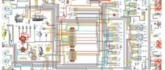
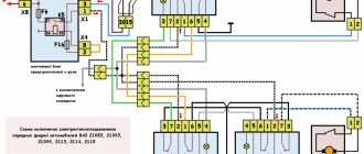
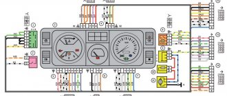
- Electrical diagram of Lada Samara 2 (left half)
- 1 – headlights
- 2 – fog lights
- 3 – air temperature sensor
- 4 – electric motor of the engine cooling system fan
- 5 – blocks connected to the wiring harness of the ignition system
- 6 – engine compartment lamp switch
- 7 – block for connecting to a single-wire audio signal
- 8 – sound signal
- 9 – washer fluid level sensor
- 10 – front brake pad wear sensors
- 11 – oil level sensor
- 12 – generator
- 13 – engine compartment lamp
- 14 – coolant temperature indicator sensor
- 15 – starter
- 16 – battery
- 17 – relay for turning on fog lights
- 18 – coolant level sensor
- 19 – brake fluid level sensor
- 20 – reverse light switch
- 21 – windshield wiper gear motor
- 22 – oil pressure warning lamp sensor
- 23 – block for connecting to the rear window washer motor
- 24 – windshield washer motor
- 25 – instrument cluster
- 26 – mounting block. Conventional numbering of plugs in blocks
- A - headlight blocks
- B - electric fuel pump block
- C - blocks of the mounting block, ignition switch, windshield wiper gearmotor
- D — interior lamp
Connection in a car service
Service station technicians won’t charge a lot of money for installing equipment and will do everything quickly.
Service station technicians won’t charge a lot of money for installing equipment and will do everything quickly.
The Uremont.com aggregator provides car owners with an interactive map indicating partner service stations, customer reviews about them, and feature articles. If you need professional advice, write your question in the chat - the answer will come quickly. A convenient way to submit a request is to fill out the online application form. In this case, the response comes within 15 minutes.
If you decide to replace the BC or find a code indicating a significant problem on the display, contact a technical center.
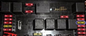
Mounting block VAZ-2113, 2114, 2115. Location of fuses and relays.
New model mounting block VAZ-2113, 2114, 2115. Location of fuses and relays.
Relay Description:
K1–relay for turning on headlight cleaners; K2–relay-interrupter for direction indicators and hazard warning lights; K3 – windshield wiper relay; K4 – lamp health monitoring relay; K5 – power window relay; K6 – relay for turning on sound signals; K7 – rear window heating relay; K8 – headlight high beam relay; K9 – relay for turning on low beam headlights; F1–F20—fuses; X11 – terminals of the wiring harness block
Table of circuits protected by fuses on the VAZ 2114
Fuse number
Circuits protected by a fuse
Rear fog lamp switching relay. Rear fog lamp lamps. Rear fog lamp switching indicator
Direction indicators, relay-interrupter of direction indicators and hazard warning lights (in hazard warning mode) Hazard warning lamp
Front interior lamp. Central interior lamp. Luggage compartment lighting. Illumination lamp for the ignition switch. Lamp for monitoring the engine management system. Brake light bulbs. Trip computer (if installed)
Socket for connecting a portable lamp. Relay for turning on the heated rear window (contacts). Rear window heating element
Sound signal. Horn relay. Cooling fan electric motor. Fan fuse.
Direction indicators, relay-interrupter for direction indicators and hazard warning lights (in turn indication mode). Reversing lamps. Relay for monitoring the health of lamps. On-board control system display unit. Instrument cluster. Insufficient oil pressure indicator lamp. Parking brake indicator lamp (brake light fuse). Brake fluid level indicator lamp. Low battery indicator lamp. Trip computer (if installed). Generator excitation winding (in engine starting mode). Front windshield wiper. Seat heating control.
Numbering of plugs in the connecting blocks of the VAZ 2113, 2114, 2115 mounting block
Diagram of the VAZ-2113, 2114, 2115 mounting block Option No. 1.
Relay Description:
K1–relay for turning on headlight cleaners; K2–relay-interrupter for direction indicators and hazard warning lights; K3 – windshield wiper relay; K4 – lamp health monitoring relay; K5 – power window relay; K6 – relay for turning on sound signals; K7 – rear window heating relay; K8 – headlight high beam relay; K9 – relay for turning on low beam headlights;
What to choose?
The range of on-board computers for the VAZ 2114 is quite extensive. But you shouldn’t take the first one you come across.
First, make sure that the computer you choose supports programs designed for the electronic control unit of the “fourteenth” model.
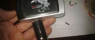
Model Gamma GF 415T
We do not recommend purchasing cheap models under any circumstances. Once you decide to install a sideboard, make sure that there is no doubt about its quality and reliability. You'll have to pay a pretty penny for it, but believe me, it's worth it.
Mounting block VAZ 2115 / 2114
Location of fuses and relays in the VAZ 2114 / 2115 mounting block
K1 – relay for turning on headlight cleaners; K2 – relay-interrupter for direction indicators and hazard warning lights; K3 – windshield wiper relay; K4 – lamp health monitoring relay; K5 – power window relay; K6 – relay for turning on sound signals; K7 – relay for turning on the heated rear window; K8 – headlight high beam relay; K9 – relay for low beam headlights; F1-F20 – fuses.
Connection diagram for the electrical equipment mounting block VAZ 2114 / 2115
1 – headlights; 2 – fog lights; 3 – air temperature sensor; 4 – electric motor of the engine cooling system fan; 5 – blocks connected to the wiring harness of the ignition system; 6 – engine compartment lamp switch; 7 – block for connection to a single-wire type audio signal; 8 – sound signal; 9 – washer fluid level sensor; 10 – front brake pad wear sensors; 11 – oil level sensor; 12 – generator; 13 – engine compartment lamp; 14 – coolant temperature indicator sensor; 15 – starter; 16 – battery; 17 – relay for turning on fog lights; 18 – coolant level sensor; 19 – brake fluid level sensor; 20 – reverse light switch; 21 – windshield wiper gearmotor; 22 – oil pressure warning lamp sensor; 23 – block for connecting to the rear window washer electric motor; 24 – electric motor for windshield washer; 25 – instrument cluster; 26 – mounting block. Conventional numbering of plugs in the blocks: A - block headlights; B — electric fuel pump block; C — blocks of the mounting block, ignition switch, windshield wiper gearmotor; D — interior lamp.
Electrical diagram of connections of the mounting fuse block for VAZ 2115 / 2114 diagram
K1 – relay for turning on headlight cleaners; K2 – relay-interrupter for direction indicators and hazard warning lights; K3 – windshield wiper relay; K4 – lamp health monitoring relay; K5 – power window relay; K6 – relay for turning on sound signals; K7 – relay for turning on the heated rear window; K8 – headlight high beam relay; K9 – relay for low beam headlights; F1-F20 – fuses
Repair of fuse block 2115 / 2114
Most fuses and relays are located in a separate mounting block installed in the air intake box on the left side of the vehicle. Through the mounting block, the wires of the engine compartment are connected to the wires of the instrument panel and the vehicle interior. The conventional numbers of the plugs in the connecting blocks of the mounting block are shown in the figure above. The diagram of the internal connections of the mounting block is also presented above.
Repair of the VAZ 2114/2115 mounting block consists mainly of replacing printed circuit boards. It is allowed to solder wires to replace burnt-out current-carrying tracks on printed circuit boards, but only if this does not require disconnecting the printed circuit boards.
Electrical diagrams of VAZ 2114, VAZ 2115, VAZ 2113
Installation instructions for on-board computer
In this article we will look at the installation process of the Prestige on-board computer with diagnostic and error reading functions.
For work we will need:
- Screwdrivers.
- The computer itself.
- Wire 1 m long.
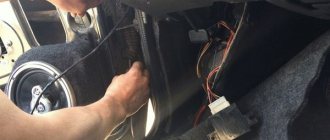
We remove the plug on the central dashboard and look for a 9-pin wiring block in it. It should be on all Samara cars. All that remains is to connect the block to the computer and that’s it, but we need to draw a K-line.
How to draw a K-line?
- We take our wire and install it in the second contact of our block.
- We throw the opposite end under the instrument panel down to the diagnostic block.
- Having stretched the cord, we connect it to the “M” socket if you have a Euro-2 socket, or to the 7th socket if you have a Euro-3 socket (it is very common that on Euro-3 it is installed on the car upside down, please note This)
- Now we connect the computer, insert it into its normal place and check.
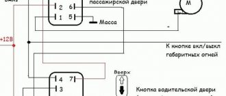
For a more complete and clear idea of the work, a diagram is provided.
What to do if there is no pad for the computer under the instrument panel?
In this case, all that remains is to assemble a new block: buy a 9-pin one and run the wires to it according to the following diagram:
- fuel consumption signal (green wire);
- ignition (orange);
- + 12 volts (red with white stripe);
- mass (black);
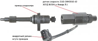
- speed sensor (brown);
- 6k line (most often gray or black);
- mute (green with red stripe);
- backlight (white wire, or can be taken from the size button);
- fuel level sensor (pink).
Tips for motorists
If on a VAZ-2114 car on the instrument panel none of the indicators installed on it work (speedometer, odometer, tachometer, fuel level and coolant temperature indicators), then the first thing the driver will have to do is check the integrity of fuse F3, which is located in the mounting block. If it has burned out, then before replacing it, you need to find the reason why it burned out, otherwise the newly installed new fuse will have the same fate as the previous one. Most often, fuses burn as a result of a short circuit.
Even if the fuse is intact, then do not be lazy to take it out and check the condition of the contacts. There are cases when the contacts oxidize, and the electrical circuit in this place is interrupted. After making sure that the fuse is intact, the next step is to check the ignition relay, which is located inside the car to the left of the steering column. It is attached to a pin upside down. In the block where this relay is inserted, you can try to short-circuit the power wires using a jumper. If the instrument panel comes to life, the ignition relay will have to be replaced.
Malfunctions
On modern VAZ models, fully electronic instrument panels are installed. When you start the engine, all indicator lights light up, and after 2-3 seconds they go out (if all systems are working properly). If, when you turn on the ignition, one or several light bulbs do not work, then you need to find out the reason by performing a number of characteristic actions.
If one or more lamps do not light, the first step is to replace the lamps themselves. All indicators of the VAZ 2114, like the backlight, are illuminated by LEDs, and during prolonged use they tend to burn out.
If replacing the lamps does not help, then the situation is much more serious. As you know, each indicator is responsible for some kind of system, and in the case when it does not work, the cause may be any element associated with the indicator light in one circuit. For example, if the battery charge sensor does not work, you need to check the entire circuit using a voltmeter, starting with the battery itself and ending with the terminals, high-voltage wires, etc. In the event that a short circuit or breakage of contacts occurs in the system, the corresponding light also does not light up.
Very often, a situation occurs when all indicators stop working at the same time. The reason for this failure is obvious - failure of the corresponding fuse. When you replace it, everything will fall into place.
- How to remove the instrument panel on a VAZ 2114
If the speedometer or tachometer on your VAZ 2114 has stopped working, then there are not many options either. The first of them is a failure in the electrical system itself. To eliminate it, you need to remove the terminals from the battery for 10-15 minutes and install it back. Thus, the system crashes and reboots. If after these steps the device still does not work, then the reason is clearly not in the instrument panel.
Also, sometimes such a problem occurs - the panel backlight does not light up. In order to correct the current situation, you need to decide: how many lamps are not working - one, several, or all.
Reasons for the failure of the instrument panel
Any component and unit on a used domestic car becomes unusable after a certain time. Poor road and climatic conditions, poor quality materials, untimely maintenance - all this leads to gradual wear and tear of all elements of the car. In a situation with a breakdown of the dashboard, everything is more complicated, because... There are no special rules for maintaining the panel. The only thing that can prevent early failure is to prevent moisture from entering the instrument body.
If the tidy on a VAZ 2114 does not work, it is worth carrying out a quick repair. The main reason is a non-working coolant temperature indicator. If the engine overheats, there is a high risk of getting it repaired. Let's consider each of the possible causes of the malfunction.
Fuse blown
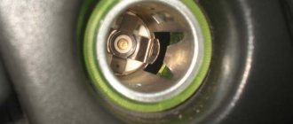
In the absence of mechanical impact on the panel, its sudden breakage is very surprising. An inexperienced driver will rush to contact a service center, or will try to disassemble the body on his own in order to find out the location of the breakdown. Note that the first action that needs to be performed when all elements on the panel are inactive at the same time is checking the fuse. Depending on the year of manufacture of the vehicle, the mounting blocks with fuses may differ. In the old-style block, the fuse is located in the bottom row . If you count from left to right, then the desired element will be the ninth in a row .
On later 2114 models, cars began to be equipped with modified mounting blocks. The safety element responsible for the tidy is located on the right side , the first in a row (from top to bottom) . In the photo it is located directly under the sliver.
Regardless of the year of manufacture, 7.5 Ampere elements were installed in the right place. If the instrument panel fails, first carry out the procedure to replace the fuses. As a recommendation, we point out that kits with spare parts are sold in all automotive stores.
Wiring damage
The next point that is worth checking if there is a malfunction is wiring diagnostics. Power for the panel elements comes through wires and plugs hidden behind the housing. To check the wiring, you need to dismantle its assembly, and then take power measurements with a multimeter.
The diagnostic process is quite simple, but for those who want to consider the instructions for using the multimeter in more detail, we recommend visiting the YouTube video hosting site. A break in the power supply circuit of the panel devices causes its complete breakdown, or the failure of only some elements. In any case, checking the wiring is the second thing to do after replacing the fuse. If the devices on the VAZ 2114 do not work, then the reasons lie in the following points.
Damage to the board
The most important part of the design is the board. Even partial damage to its surface causes serious disruptions in the readings of the tachometer, speedometer, temperature and fuel level. The board burns out due to a short circuit. Re-soldering contacts on the VAZ board is a waste of time. The fact is that after such a repair the board will not last long and will fail again. The solution to the problem is to completely replace the element with a new one.
Hard case
Until now, situations have been sorted out when the torpedo still showed some signs of life. If non-working power windows, turn signals, and windshield wipers have been added to the devices, the issue is no longer a matter of relays and fuses.
There may be 2 options:
- The contacts on the ignition switch are burnt. In principle, after installing the relay (even on the VAZ-2109 version), this problem rarely arises. However, the possibility remains. The lock is removed, the contacts are checked and, if necessary, cleaned;
- Mounting block. There may be burnt tracks on its board. The only thing that will save you is replacing it with a new one. However, the cost is by no means astronomical, and the installation is available as a standalone option.