The VAZ 2110 has been equipped with an injection engine since the early 2000s. This engine not only brought the “ten” to a new level, but also increased its reliability, as well as technical characteristics. As many people know, by now almost everyone has encountered an injection engine, and everyone knows that in such an internal combustion engine there are many different sensors responsible for the operation of the entire engine and the car as a whole. Each sensor performs its own function. For example, the VAZ 2110 speed sensor is responsible not only for the readings on the speedometer, but also for several specific functions that you clearly did not know about.
In this article we will talk about the speed sensor for VAZ 2110 cars, namely its purpose, design, functions, location, signs of malfunction, cost and self-replacement.
Design
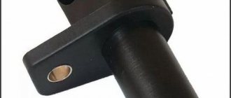
The sensor on the VAZ 2110 comes in two types, and it depends on which gearbox is installed on the car. If the gearbox is from a VAZ 2108, then the sensor is installed on a threaded connection, and if the gearbox is from a VAZ 2110-12, then the sensor is installed through an o-ring and pressed with a bolt to the body.
The design of both sensors is different; one of them is electromagnetic, and the second, older one, converts mechanical movements into electrical signals.
On the left is the sensor of the new type, and on the right is the old one.
Tuning the dashboard of Lada 2114
To make their car distinctive, many motorists resort to tuning.
Although this is a troublesome task, it is worth it. Everyone strives to make the salon spectacular and cozy. The dashboard is a favorite place for tuning.
Backlight tuning
To make the panel devices look stylish and modern, they can be modernized. Let's look at how backlight tuning is done.
You can improve the appearance of a vehicle yourself, since the process is not at all complicated.
Everything you need for tuning:
- panel disassembly;
- removing the shield;
- tune the necessary parts;
- put in place.
The first step is to replace regular yellow light bulbs with bright LEDs. Chinese diodes are cheaper, but they will not last long. To ensure that the light comes directly from the diodes, heat shrink is put on them, and the arrows will be clearly visible even in the dark.
The diode wires are connected to the backlight from the machine stove. To change the color of the arrows, a red diode is placed under each arrow. The light from the arrows will acquire a rich, bright red color, which will noticeably update the panel.
Blue light bulbs are popular. The central panel is also subject to tuning, respect is guaranteed. The glow becomes soft and irritates the eyes when driving.
Europanel
To give a modern aesthetic look, you can install a europanel.
The material of the panel is soft, rich, and less noisy. The original warning lamps and odometer make the panel modern and fashionable. It is equipped with many signal sensors. A special feature of the Europanel are sensor signals and airbags. White-blue LEDs also look beautiful. Typically, up to 50 LEDs are needed for tuning. If the glow of the diodes is very bright, then you can try to adjust it. Some VAZ components have this capability.
You can also tint the instrument panel, which will also look great. Improving the panel offers ample opportunities for creativity among car enthusiasts and designers. As a tuning option, you can install a start button, which will give the interior a distinctive style and modernity.
By the way, if the modernization will be carried out with your own hands, in order to avoid problems with the traffic police, you need to write a statement about the planned changes in the design of the car and wait for permission from the traffic police. After making changes, you need to undergo a technical inspection, where appropriate changes will be made to the registration documents.
Symptoms of a problem
If the sensor fails, the car has only two possible signs of a malfunction: a non-working speedometer and the absence of increased speed when coasting. The sensor is quite cheap and does not require much effort to replace; replacing it is quite simple.
Possible sensor failures
Most often, the VAZ 2110 speed sensor fails for the following reasons:
- Open circuit;
- Oxidation of contacts;
- Cutting off the speedometer drive shaft;
- Damage to the sensor housing;
- Contamination of the sensitive part;
- Chips sticking to the sensor;
If the speedometer on your car does not work, you need to inspect the speed sensor for such breakdowns.
What is the Hall effect
It lies in the fact that during the interaction of magnetic and electric fields, when the electric field flows in a certain way through the magnetic field in which the semiconductor wafer is located, a potential difference appears on it, the so-called Hall voltage.
This effect has gained practical application in DS because when moving, this voltage is converted into a pulse-frequency signal, which is transmitted to the controller. The higher the speed, the higher the frequency of the signal. It is calculated that the DS emits 6004 pulses per kilometer of travel. Based on the interval between these pulses, the controller calculates the speed of the machine.
Differences between VAZ 2110 speed sensors
There are two types of speed sensors, old and new. Let's look at each of the sensors in more detail.
Old style sensor
This part is made entirely of plastic, and inside it there is an electrical circuit that converts mechanical rotations into impulses and transmits them to the computer. This sensor is installed in the mechanical speedometer drive, which is located in the gearbox housing. The sensor connector is located on the wires.
New sensor
A single piece molded from plastic with a special O-ring to seal the system. The sensor is secured using an M6 bolt. There is an electromagnetic element inside the sensor that reads readings from the gearbox gear and then transmits the readings to the engine control unit.
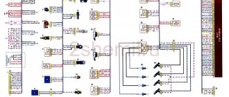
VAZ 2114 instrument panel pinout
Electrical connection diagram for the VAZ 2114 instrument panel (Click on the picture to enlarge)
- – rear window heating switch;
- – rear fog lamp switch;
- – switch for headlights and direction indicators;
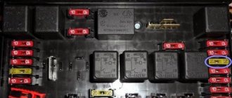
- – mounting block;
- – windshield wiper switch;
- – fog light switch;
- – display unit of the on-board control system;
- – block of the instrument panel harness to the additional harness;
- – instrument cluster;
- – instrument panel harness connector to the on-board computer harness;
- – block of the instrument panel harness to the ignition system harness;
- – block of the instrument panel harness to the side door harness;
- – fuse 16 A;
- – fuse 16 A;
- – ignition switch;
- – lighting switch;
- – heater electric motor;
- – additional resistance of the heater electric motor;
- – ignition switch unloading relay;
- – rear fog lights relay;
- - starter relay;
- – socket for connecting a portable lamp;
- – cigarette lighter;
- – block of the instrument panel harness to the wiring harness of the glove box lighting lamp;
- – illuminator;
- – illuminator;
- – illuminator;
- – heater switch;
- – instrument lighting regulator with rheostat;
- – brake signal switch;
- – horn switch;
- – hazard warning switch;
- – backlight lamp for the heater control panel;
- – fuse 16 A;
- – seat heating relay;
The panel pinout is a diagram, but the diagram described in words seems easier for many. The contacts located on the instrument panel, and there are only 26 of them, are responsible for the operation of the indicators on the panel itself.
If a plus is applied, then each of the contacts shows information and the state in which the car is currently located. The panel is equipped with sensors and signal indicators, and the panel is controlled using an electronic unit.
Inside the panel there are two pads - red and white. Fuses, inputs and outputs, controllers are connected to a specific plug. If the sensors fail, they need to be replaced.
You can check the serviceability of the wiring by disassembling the instrument panel. Oxidized or damaged wires must be replaced. Indicator lights may fail. Burnt out light bulbs must be replaced with new ones.
A faulty lamp sensor must also be replaced. The contact between the board and the lamp must be well connected, otherwise the ends of the contacts should be cleaned, bent, and if necessary, replace the lamp socket.
If the backlight stops working or the radio is faulty, the fuse must be replaced. Maybe the damage is not in the fuse, but in the wiring, which also requires replacement.
A short circuit in the fuse can also damage it.
Sensor pinout
Damage to the speed sensor wiring is a fairly common problem, since it is located quite low and this leads to the destruction of its wires and, therefore, to their unusability. To restore the wiring, you need to know the pinout of the DS VAZ 2110.
Sensor pinout
Connector pinout
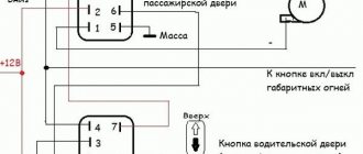
Pinout of the VAZ 2114 window lifter button
A broken window regulator on a car is not only a problem that deprives the driver and passengers of a comfortable ride.
And also an incident that can attract the attention of a traffic inspector for violation of traffic rules. Therefore, knowledge of the design features of a car can help the car owner in a variety of situations. This article provides information on how to pin out the power window button on a VAZ-2114, what may cause the mechanism to break down, and the basics for troubleshooting problems in this device.
Replacement
To replace the speed sensor on a VAZ 2110, you only need a 10 mm wrench.
Since the VAZ 2110 uses two types of sensors, we will consider ways to replace each of them.
- Remove the connector from the sensor;
- We unscrew the sensor, depending on the type, or unscrew the sensor itself along the thread, or using a 10 mm wrench, unscrew the bolt securing the sensor to the gearbox housing;
- We remove the sensor from the gearbox;
- Installation is carried out in reverse order;
It is necessary to install the old-style sensor by inserting the square shaft into the speedometer drive groove inside the gearbox.
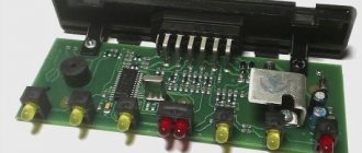
Connecting the control unit to cars with a mechanical speedometer.
When installing the control unit in cars with a mechanical speedometer, it is necessary to install a pulse speed sensor in the gearbox and replace the mechanical speedometer with an electronic one.
In this case, the input of the electronic speedometer is connected to output “B7” of the control unit. The output of the speed sensor is normally connected to the control unit. The number of pulses at output “B7”, necessary for normal operation of the speedometer, is programmed in the control unit in the “Calibration” mode.
The figure shows a standard European speedometer with connector: ISO 16844-2:2011 (same as on the KU). Speedometers with other types of connectors are connected in the same way, depending on the purpose of the contacts.
In the KU with versions AVLG816.00.00-10...15 (serial numbers No. 4, the output stage B7 was connected to the on-board power supply (12 or 24 V) through a resistor. Therefore, before connecting, you should check the technical data sheet for the speedometer what signal level is acceptable at the corresponding speedometer input.
If the Input is designed for a voltage of no more than 9.5 V, then a resistor Rs* should be connected (shown in the diagram). Select the resistor value according to Table 2. For KU versions AVLG 816.00.00-16 and higher (serial/factory numbers from No. 000 and higher), there is no need to install an additional resistor.
Table 2.
| Element | Rating at Vcc=12 V | Nominal Vcc=24 V | Note |
| Rs | 15 kOhm±10% 0.125 W | 3.3 kOm±10% 0.125 W | Voltage divider resistor. |
Checking the performance of the DC
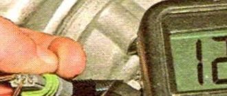
Checking the DS is necessary if typical signs of its malfunction are detected. This device can be checked in several ways, including without removing the device from the car. To do this, you will need a multimeter and a regular 12 V light bulb.
A multimeter is a device for testing electrical networks and devices that consume electricity. This is an indispensable thing for diagnosing a car, so it makes sense to buy it for the garage, since it is not expensive (about 400-600 rubles).
Checking the speed sensor - method No. 1 (with removing the DS):
- We dismantle the DS (you can read how to do this in the next section of the article);
- Set the multimeter to alternating voltage mode;
- We close the tester probes to the contacts in the DS block: the first - to the contact going to the dashboard (it is in the center), the second - to the ground contact;
Multimeter connection method
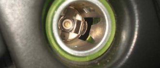
- On the front end of the DS housing you will see a rod, when rotated the sensor is activated. Accordingly, in order to check the device, we need to twist it; this is most conveniently done by placing a metal tube of the appropriate size on the axis.
When the sensor rod rotates, the tester should show AC voltage spikes. The faster the rotation speed, the larger the voltage surges should be. If this does not happen, the device is faulty.
The second method allows you to check the sensor without removing it from the car, but to implement it you will need to drive the fourteenth into the inspection hole.
- We drive the fourteenth into the pit and jack it up in the area of the left front wheel;
- We find the DC and disconnect the block of wires connected to it;
- We connect the electrodes of the multimeter to the ground contacts and send a signal to the ECU (central and rightmost contacts);
- We rotate the wheel in the air and check the tester readings for voltage surges.
If for some reason you cannot check with a multimeter, you can use a regular 12 V light bulb.
Ignition switch pinout for VAZ 2114
I was planning to install auto start and was faced with the fact that in the smart book the ignition switch circuit is not clear =( . I decided to share the circuit and pinout
Connection diagram of the ignition switch VAZ 2113 2114 2115
The vehicle is equipped with an ignition switch (lock) type 2110-3704005 or KZ-881.
The ignition switch is equipped with an anti-theft locking device, a lock to restart the starter when the engine is running, and an illuminated lock socket.
The locking rod of the anti-theft device extends when the key is removed from the lock (the key can only be removed in position “0”). When the key is turned from position “0” to position “I”, the locking rod is retracted inside the lock, contacts “30” and “15” of the ignition switch are closed.
When the key is turned to position “II”, voltage is also supplied to the starter relay. From this position, the key automatically returns to position “I” under the action of a spring. You can turn the key back to position “II” only after first turning it to position “0”.
The circuits that are closed at various key positions are shown in the table below. The ignition switch (lock) connection diagram is shown in the top figure.
. 2705, 33021 “”
. 9.51. : 1 , 2 5-54, 3
, p. 9.51. 5-54 10 3, 6+1 200250. :
. 9.52. : 1, 2, 3, R1 -0.25-10, V1 102
. 9.53. : 1 ; 2 ; 3 5-54
, . 9.53. 5-54 1 6 , 122 200250 . 240 1000+100 -1, 960 4000 -1.
P. 9.54. : 1 ; 2 ; 3 1, 4, R1 -2-330, R2 -2-120, R -2-15
, . 9.54. RI, 0, R2 1/2, R3. . : 330+15, 11+5. 70 ( ) 118+10 .
25 14001900 , 80 200270 .
. 9.55. : 1 ; 2 ; 3 1 ; R1 -2-250
. 9.56. : 1 ; 2 ; 3 1 ; 4 ; R1 -2-180 ; R2 -2-60
, . 9.56. R1 1.5 /2, R2 4.5 /2. .
290330 , 1,5 /2 170200 , 4,5 /2 5080 .
30 I (5-48). , . 12 14 +0.4 .
Wiring diagram for the ignition switch on VAZ-2113, 2114 and 2115
Wiring diagram for the ignition switch on VAZ-2113, 2114 and 2115
Pinout of the ignition switch VAZ-2113, 2114, 2115:
- comes +12V for the microphone of the sensor of the inserted key;
- the mass comes when the driver's door is open;
- +12V goes to the starter (pin 50);
- +12V goes out after turning on the ignition (pin 15);
- +12V goes out when the key is inserted to pin 5 of the BSK;
- comes +12V to illuminate the lock cylinder;
- +12V comes from the battery (pin 30);
- not used.
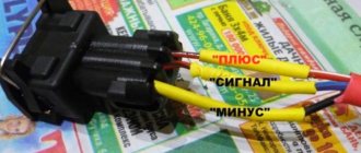
| Photo 1, pinout of the ignition switch of a VAZ 2114 | Photo 2, pinout of the ignition switch of the VAZ 2114 |
Sources
- natapku.ru/ustrojstvo/panel-priborov-vaz-2114.html
- autoschemes.rf/shemy/vaz/2113-14-15/151-shema-elektrooborudovaniya-avtomobilya-vaz-2115.html
- 2shemi.ru/raspinovka-pribornoj-paneli-vaz/
- galantmotors.ru/document/shema/2114/2114_scheme_panel.php
- drive2.ru/l/186644/
- galantmotors.ru/document/shema/2114/2114_zamok_zajiganiya.php
- drive2.ru/l/544700810253041946/
Installation of an electric window regulator (ESP) on a VAZ-2114
The most popular window lift systems on the VAZ-2114 are rack and pinion types. Their connection is carried out according to the scheme described below.
- Disconnect the on-board power supply from the supply. To do this, remove the terminals from the battery, you can close one - the negative one.
- All the wires that come with the ESP on the VAZ-2114 are twisted together into a bundle.
- The mounting block is removed by unscrewing the screw that controls the position of the latch.
- A wiring harness is mounted into the block in place of the connector of the block.
- The door trim is removed.
- The ESP is installed, along with all the buttons and keys.
By the way, you can make a choice if you wish. Install the buttons and keys that control the window regulator either on the door panel or on the control unit. In the latter case, you will need an additional wire and knowledge of the theory of pinout of the ESP button.