Electric windows in modern cars are no longer a rare system that many can only dream of. Even AvtoVAZ installs this system from the factory on new models. But any mechanism has wear and tear, which is why from time to time you need to know the pinout of the VAZ 2114 window lifter button, the complete system diagram, etc. Car owners are used to repairing cars themselves, and despite the fact that the mechanisms change, they still try to study them and get rid of faults on their own.
Video: How to connect power windows yourself easily and quickly:
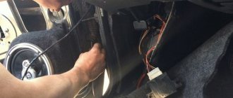
Installation of window regulators: step-by-step instructions
1. Removing the window regulator
Before carrying out any work, first remove the weight from the vehicle battery to prevent an accidental short circuit in the circuit. Then do this:
- Take a Phillips screwdriver and use it to remove the three screws holding the door pocket in place. Next, remove the product latches from the holes in the door trim. Note that the self-tapping screws for attaching the pocket simultaneously hold the lower part of the door trim on the VAZ 2115. In this case, the pocket panel plays the role of a speaker trim.
- Using a screwdriver, pry up the window handle latch by inserting the tip of the tool between the latch and the socket.
- Disassemble the socket, then use a screwdriver to pry off the door handle cover.
- Take a Phillips screwdriver and remove the couple of screws holding the handle in place, then remove it.
- Using the tip of a screwdriver, pry up the inner handle trim and remove it.
- Unscrew and disassemble the button, then remove the handle and the front of the mirror controller.
- Remove the door trim. Here you will have to overcome the resistance of the product clamps (pistons).
- Using ten heads, unscrew a pair of bolts securing the glazing bead to the window regulator.
- Unscrew the nuts of the various window lift guide supports: two central, one lower and one upper.
Once you have done the above work, take a number eight screwdriver and unscrew the three locking nuts holding the window mechanism in place. Next, remove the lower pin of the drive mechanism from the hole in the door panel. Take a screwdriver and use it to remove the upper guide pin from the hole, then remove the window regulator through the hole in the door panel.
The video shows how to get to the window regulator on a VAZ 2114, 2115
2. Installation and connection of the window regulator
Before installing the window regulator, lower it. If necessary, power the gear motor from a car battery. So, let's do this:
- Install the window regulator into the door panel opening, then insert the window mounting studs into the corresponding holes.
- Install the nuts onto the studs and tighten them with a ten-hole socket.”
- Position the gear motor until the holes in the guide mechanism align with the holes in the glass fork.
- Use the bolts to attach the power window track to the window frame.
- Apply lubricant to the rubbing elements of the mechanism.
Remember that when installing a window regulator, it is not recommended to apply lubricant until the installation is complete. Otherwise, there is a high risk of lubricant getting on the interior panel during operation.
Before installing the window regulator, prepare the necessary diagrams and follow the manufacturer's recommendations. You will need wiring diagrams for the car and the window regulator.
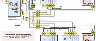
Connection diagram for electric window VAZ 2114
Then do this:
- Apply power to the side window up/down switch assembly using the bellows.
- Connect the negative terminal to the battery terminal.
- Connect the wires and make sure the device works.
- Insert the plug into the hole in the door trim for the lift handle shaft.
- Reinstall the door trim (no pockets yet), then insert the switch harness connector into the hole in the trim.
- Insert the power window switch instead of the plug.
- Turn on the switch and insert the pocket.
Connection diagram for electric window VAZ 2115
Installing a window regulator allows you to increase the level of comfort when driving a car and get rid of annoying car handles. The main thing is to have the installation diagram at hand and strictly follow the instructions in the article. In this case, installing and connecting the window regulator on VAZ 2114, VAZ 2115 or VAZ 2113 cars will not be difficult.
Electric drives
Panther alarm, useful information, how to install. Panther car alarm connection diagram Pantera alarm diagram
Drives with electric motors are much more advanced. But they were installed on “classic” VAZ cars exclusively by car owners - this option was not provided at the factory. The main thing (according to those who have been producing these cars for almost 30 years) is wheels on an iron body and some kind of motor, as long as it drives this entire structure.
If you take a closer look, you will see that the designers did not bother themselves with comfort; they only thought about how to save on production. And in the car circuit there was no provision for connecting power windows. Therefore, you have to install all the wiring yourself.
But many car owners took on the responsibility of the factory and began installing power windows themselves. Most often, the choice falls on hinged lever mechanisms, which have several advantages:
- Quite low cost of the kit.
- Electric windows are easy to install.
- There is no need to look for components - everything needed for installation is already available, including wires and buttons.
- The devices are highly reliable, work quickly and do not make noise (the latter advantage is more relevant for modern Vesta than for the “seven”).
Refinement and installation of the ESP unit from Kalina in VAZ 2113, 2114, 2115
Production of extension wires for modification of the ESP unit from Kalina in VAZ 2114
This revision is secondary. I installed the lock only because I had long wanted to control the central locking not from the “peak” on the driver’s door, but from a button. It was not possible to find decent buttons to distinguish them from each other, so it was decided to install a block from Kalina.
I searched for a long time, read, selected options, and now I have matured.
— ESP buttons (from VAZ 2114.3 pcs. Price: 270 rub.
Save to album
— Chip for ESP Price: 100 rubles
— I took the terminals “mom”, “dad”, “euromam” with a reserve: 30 one, 30 others and 10 thirds
— ESP wiring (from VAZ 2114.3 pcs. Price: 540 rub.
— Microcircuit with three contacts for small terminals Price: 30 rubles
Next I move on to describe the making of the harnesses.
The finished wiring of the ESP VAZ 2114 is mercilessly cut. Next, we take a bend and begin to crimp the Eurowires with terminals. We fold the other end with the male terminals. And we put a heat-shrink tube on the “male” terminals. We secure the strands with heat shrink loops. And we get ready-made wiring for the ESP block.
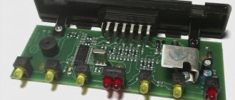
ESP unit connector pinout:
1. +12 V for the driver's window (window goes down. 2. +12 V for the driver's window (window goes up. 3. Weight 4. + 12V for the driver's window 5. Weight 6. + 12V for the passenger window 7. Absent 8. Dimensions 9. + 12V to the passenger window (window down. 10. + 12V to the passenger window (window up.
Then we again take the finished wiring from the ESP, mercilessly cut it, take the bend and crimp it with the “mother” terminals. We fold the other end with the male terminals. And we put a heat-shrink tube on the “male” terminals. We secure the strands with heat shrink loops. We get the wiring harness for the central locking control.
Interesting: is it cold in the car? All about replacing antifreeze
CZ connector pinout:
1. Closing 2. Weight 3. None 4. Dimensions 5. Backlight weight 6. None 7. Opening
Again we take the finished harness from the ESP and again mercilessly cut it. We fold them with the “mother” terminals. We fold the other end with the male terminals. And we put a heat-shrink tube on the “male” terminals. We secure the strands with heat shrink loops. We get the ESP passenger door trim.
Next, take the ESP buttons from the VAZ 2114. Let's take it apart. All we need from them is the body.
In the upper part, we remove all excess with a round file.
First we thread the top of the button. Based on the pinout, we insert the “plug” terminals from the finished wiring into the modified buttons. We secure the terminals in the body of the button with super torque. Putting the buttons together. We get a block for connecting to the original wiring. Fill the top of the resulting pads with silicone.
To make it easier, here is a pinout alignment diagram.
On the left is the block of the Kalina block, on the right is the VAZ 2114
1. + 12V ESP driver (window goes down. - 7 contact (in the driver’s button. 2. + 12V ESP driver (window goes up. - 1 contact (in the driver’s button. 3. Ground) - 5 contacts (in the driver’s button. 4. + 12V ESP - contact 2 (in the driver's button. 5. Ground - 6 contacts (in the driver's button. 6. + 12V ESP - 2 contacts (in the passenger's side button. 7. Absent 8. Dimensions - 4 contacts (in the driver's button. 9. Passenger + 12V ESP (window goes down. - 7 contact (in the passenger button. 10. + 12V ESP passenger (window goes up. - 1 contact (in the passenger button).
To illuminate the central locking button
4. Dimensions - 4 contacts (in the passenger button. 5. Backlight ground - contact 3 (in the button on the passenger side.
I think this method is the most optimal, since there is no need to bump into the original wiring. You just need to connect the chips and enjoy your work.
This completes the preparatory stage. Installation coming soon.
Installing an ESP unit from Kalina in a VAZ 2114
I was going to install the Kalina ESP lock in the driver's door and the Kalina ESP button in the passenger door.
Due to extensions. Because I made them and that's what I did.
Firstly, I don’t really like touching and cutting standard wiring. I hate connecting with a twisted cord. Secondly, I always try to make changes or improvements so that everything can be returned. And so that after return there is no trace of alteration left. Thirdly, extensions are needed for smooth skin removal. Since the podiums are screwed tightly, removing the trim is very inconvenient. The ESP wiring is in the way; it is short. And then it’s very inconvenient to take the ESP harness onto the podium and put the button in place.
There were no problems with inserting the block and button. We measure the button with a caliper and transfer the dimensions onto thick cardboard. Then cut out the template with a sharp knife.
Create a template for the block. It is necessary to disassemble the lock: remove the central locking button and the ESP button lock. Next, we place the body on the cardboard, outline the outline and cut out the template.
Initially I wanted to connect the central locking button without turning off the microswitch, but nothing happened when connecting this circuit. The central locking continued to work from the key and the “belly button” in the driver’s door, but did not respond to the button in the lock. This is due to the permanent closure of one of the two contacts of the microswitch. I still haven't figured out how to get around this problem, so for now I turned off the microswitch and pressed the central locking button. Turning off did not affect the operation of the signal in any way, since the driver's door electric drive is connected in parallel with the other three.
This scheme doesn't work
Next, we draw the patterns, trace the contours with a marker and carefully cut out holes in the skins with a stationery knife.
Insert the block and button. We connect previously assembled add-ons. We hide the threads at the joints in the hole of the podium.
These plugs cover the holes for the ESP buttons in the passages. I glued it onto black silicone. So that they can be safely detached without damaging the podium itself.
We put on our jacket and rejoice.
Indeed, it has become more comfortable and attractive. If you want to close, the button is pressed. If you want to open it, press the button again. Beauty.
Diagnostics and repair of the ambient temperature sensor on VAZ 2113, 2114, 2115
I was prompted to write this post not so much by the desire to share the repairs I made, but by the description
Let's get started
Before you start connecting the window lifter to the VAZ-2106 or VAZ-2107, and even the VAZ-2109, keep one nuance in mind. Actually, you should have encountered this even when purchasing a window regulator. The fact is that on these models there is no “window window” and the glass is lowered across its entire width. Because of this, the most common models of window lifters are not suitable: there is simply not enough space. So the connection diagram for the window regulator on the VAZ-2106 and two other models is slightly different from the standard one and requires different equipment. Fortunately, sellers are well aware of this and usually offer a suitable solution.
First of all, read the instructions. It is written very clearly and understandably how exactly to install the electric motor and what to attach it to. According to the holes, the fastening bar coincides with the three bolts that we unscrewed during dismantling, so there will be no difficulties. After installing the window lifter mechanism, connect it to the brackets on the glass. Now, again in accordance with the instructions, lay the wiring to the battery. There is a special technological tunnel in the door for this, so run the wire inside it. This will protect it from chafing and protect it from atmospheric moisture. Which by no means eliminates the need for proper, intact insulation! The wires are connected using four-pin connectors, but if you have any problems with this, you can use the old fashioned method: strip, connect and wrap with electrical tape. But this is still not recommended.
After that, we begin to find a place for the button. As practice shows, it is not very convenient to install it on a door in 2106 or 2107; the optimal solution is to install it on the dashboard. There is space there and it is relatively easy to run wires there. Having made a hole (or if you have free ones, simply remove the plug), insert the seal and the toggle switch itself, and connect the wiring. Actually, all that remains is to put the door back together and this is where the connection of the window lifter on the VAZ-2107, VAZ-2106, VAZ-2109 ends. Unless you can, before putting the casing in place, connect the negative terminal and check the functionality of the assembled system.
Button for dimensions and low beams of VAZ 2114: features and replacement
For greater convenience, the button for turning on the low beam headlights and the button for turning on the dimensions of the VAZ 2114 are made in pairs and are located on the car's European panel. Both are equipped with additional built-in LEDs (two for backlighting and one indicator for side lights).
As a rule, there are no problems with the operation of these buttons, but if necessary (for example, in case of breakdown), you should know how to replace them.
Everything is done in the following order:
- Remove the cover under the control panel (easily removed by hand, no tools required).
- Pull the buttons inward by pressing them from the inside.
- Gently pull the button, wiggling it slightly, and remove it from the shoe.
- Install the new button into the shoe.
- Place the buttons back into the panel.
As you can see, replacement can be done almost instantly, without much effort and without the use of special tools.
Another important point that should be highlighted is the assignment of the button pins to the dimensions of the VAZ 2114. This may be necessary, for example, when replacing an old type button with a button for a Europanel.
You can see this more clearly in the following diagrams: for the old type buttons .gif»/> for the new type buttons This is interesting: the starter is idling
The redesigned button follows the pattern shown here. Soldering the LED itself from board to board is highly not recommended, since this requires a soldering station equipped with a hair dryer, a special flux and high qualifications in working with them.
First, we need to remove the main button from the car panel (how to do this has already been described above).
After it has been removed and disconnected from the wires, do the following:
- remove the keys by prying them off with a flat screwdriver;
- disassemble the button housing by pressing the latches with a screwdriver (the buttons themselves should now be in the “on” position);
- we see that there are two diodes on the size button (backlight and indication), and on the low beam button there is only one backlight button;
- remove a couple of legs and a couple of contacts from the donor button;
- rearrange them into free spaces on the task button;
And there are power supplies, but only with 2 buttons ESP and CZ (for example, 1118-3709810-10 (351.3769)). You can buy it at a price of 600 rubles.
Wiring diagram and pinout of the Kalina ESP unit: Main connector:
- driver door motor
- driver door motor
- mass (only one is possible, they are combined inside)
- + 12V for driver's window
- weight
- + 12V for passenger window
- absent
- size
- 3 foot buttons in the passenger door
- 6ft button in passenger door
Central locking button:
- closing
- weight
- absent
- size
- backlight weight
- absent
- opening
You can buy a Kalinovsky lock and ESP control buttons in online stores (section “Spare parts”) And if you modify the VAZ-1118 control unit with electric windows, you can install 4 buttons. You just need to combine the block 1118-3709810-10 with two-piece buttons 2170-3763040. So, the ESP power unit with 4 buttons and central locking is ready! Instructions on how to move the ESP control unit from the tunnel to the driver's door.
By the way, it is not at all necessary to stretch thick wires through the door if you are installing a window closer (for example, beta10, which has thin low-current inputs).
To get rid of constant fines from the camera, many of our readers successfully use Special Nano Film for their numbers. A 100% legal and reliable way to protect yourself from fines. After reviewing and carefully studying this method, we decided to offer it to you.
To get rid of constant fines from the camera, many of our readers successfully use Special Nano Film for their numbers. A 100% legal and reliable way to protect yourself from fines. After reviewing and carefully studying this method, we decided to offer it to you.
Types of window lifters
Electric window lifters used in modern domestic (and not only) cars can be divided into 3 main categories:
- Cable ones are the most affordable, but they are also weak and slow. Their only advantage is maintainability - if the motor fails, it can be purchased separately and installed in place of the broken one.
- Rack and pinion ones are faster and quite reliable, but require regular inspection and lubrication to achieve a long service life.
- Lever-hinged ones are the most modern. They are distinguished by durability, low maintenance requirements, and a combination of high operating speed and high power. Even frozen glass can be moved without much effort.
Do-it-yourself installation of glass closers on a VAZ
The closest one is designed to work in conjunction with a car alarm or other device that has a special output, on which a pulse of negative or positive polarity appears when the state of the system changes (for example, when arming).
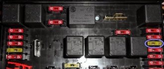
To begin the installation, you need to check whether the car windows open and close with the buttons when the ignition is off; if not, you need to find the relay in the fuse block that is responsible for opening and closing the power windows, remove it and replace it with a jumper, as shown in the photo. Without this jumper, glass door closers will not work.
Rice. 1. Automotive fuse block and relay VAZ 2114
Rice. 2 A jumper instead of a power window relay is a guarantee that the closer will work for you.
After the preparatory stage, remove the driver's door trim (the passenger door trim remains in place)
Figure 3. Remove the driver's door trim to install the nearest one.
And install the nearest one on the car door as shown in the photo.
Rice. 4, Fig. 5. Installing the door closer module on the driver's door
Let's look at the installation diagram of door closers.
Fig. 6 Closer connection diagram
Figure 7. Comments on the connection diagram closest to the window.
And the electrical circuit of your car (for example, the closest one was installed on a VAZ 2114 car, we are only interested in a fragment with the same windows and appearance.
Connect the black wire to vehicle ground. Or, stupidly, to the black wire, because it is connected to ground.
We connect the white-yellow wire and the yellow wire to the central locking of your car.
We are looking for the wire responsible for opening the windows of the driver and passenger doors and connect their 4 wires in an empty space.
"Direct connection" means that the wire is cut in half and the connection is made from the button side and the motor side.
We cut the orange wire in half and connect the wires from the one closest to it on the button side. On the side of the button it is green with a black stripe, and on the side of the motor there is a green wire for the nearest glass.
We cut the blue one with a black stripe in half and connect the wires from the one closest to it on the button side. On the side of the button it is blue with a black stripe, and on the side of the motor there is a blue wire for the nearest glass.
All connections are carefully soldered and insulated.
We assemble the door trim and use door closers.
Connection instructions
To connect the button of the mechanism that raises the glass, you will need a whole set of tools and materials. If the installation is carried out on several doors, then you will need the same number of kits as there are doors.
- female-male block having two contacts;
- connection connector;
- 2 male terminals;
- 2 large female terminals and 7 small terminals;
- beet lifting mechanism key;
- glass and key connector;
- 4 meters of wire with a cross section of 0.75;
- 7 pistons for the door.
Electrical connection diagram
If the key for raising the glass is installed directly in the door, then its installation will consist of the following steps:
- Before work, you should turn off the power to the car by removing the negative terminal from the battery.
- To access the glass lifting mechanism, the trim must be removed.
- The power window button is installed on the driver's door; you need to run wiring from it to those doors where the same keys will be installed.
- There is a black and white 12 V wire on the power window relay. Connect 2 red 12 V wires to it.
- On the car door there are blue and gray wires connected to the window lift motor. The prepared wires need to be connected to the block connector: black and white to the blue wire, and black to the gray.
- There should be 5 wires connected to the button. The black wire is responsible for ground; red receives 12 V; black and white goes to blue; white — illumination of power window buttons; The black one is connected to the gray one from the block.
Switch connection pinout
It is necessary to connect wires with terminals using the following diagram:
- red 12-volt connects to hole #2;
- black and white (from blue) – hole No. 3;
- white (backlight) – hole No. 4;
- black (“ground”) - hole No. 5;
- black (from gray) - hole No. 6.
It is important to correctly connect all wires to the appropriate sockets of the connector, otherwise the control buttons will not work. Then you need to take black and black-and-white wires of the appropriate length and insert the black one into socket No. 1, and the second into socket No. 2
The loose ends should be crimped using large female terminals and connected to the new connector. In this case, you need to make sure that the connected black and white wire is directed to blue, and the black wire is directed to black
Then you need to take black and black-and-white wires of the appropriate length and insert the black one into socket No. 1, and the second into socket No. 2. The loose ends should be crimped using large female terminals and connected to the new connector. In this case, you need to make sure that the connected black and white wire is directed to blue, and the black wire is directed to black.
At this stage, the connection is considered complete. All that remains is to install the glass and the window lifter button, securing them with sealant in a specially made connector in the door trim.
Thus, you can connect the switches for raising the glass yourself, if you use the connection diagram and have experience in electrical work. This will give you the opportunity to improve your car without resorting to the help of a car service.
Sorry, there are no surveys available at this time.
Connection diagram and pinout of VAZ power window button
Electric windows (ESP) are convenient devices for controlling the side windows of a car, which are controlled by a special button and make it possible to lower or raise the side windows without rotating the previously used handles. This option is provided only in some modifications of the VAZ car, but nothing prevents you from purchasing a ready-made unit and installing it yourself.
The most preferred are rack-type ESPs, so as an example we will describe the process of their installation.
The connection diagram for the window regulator on a VAZ-2110 car is as follows:
- remove the negative terminal from the car battery to stop the supply of voltage to the on-board power supply network;
- we take the wires that come standard with rack-and-pinion window lifts and make a kind of harness out of them that makes connection easy;
- remove the car mounting block, which will require unscrewing the self-tapping screw that secures the special latch;
- turn the block over and carefully install block Ш1 of the pre-prepared wiring harness into the corresponding connector;
- dismantle the door trim;
- we pull the wires to the electric window drive. To do this, you will need to carefully pass them through the holes in the door itself and the body pillar on the desired side.
After this, buttons or keys are installed that will be used to control the power windows. Depending on your desire, they can be attached either to the door trim of a VAZ-2110 car, or to an existing control panel. In the first case, you will need to use an additional wire, which will allow you to equip the key backlight.
Replacement cost
Replacing VAZ-2114 window regulators is cheaper than installing electric mechanisms to replace manual ones. If, in order to simply change the window regulator, you need to disassemble the door trim, dismantle the old mechanism and install a new one, then to install an electric version instead of a manual one, you need to partially disassemble the instrument panel, select a power source and run the wiring from it inside the door. This work requires the intervention of an electrician. Because power cannot be taken from anywhere: the source must match the power of the electric drive, and in the event of a short circuit, the fuses must protect the main wiring of the car. In addition, the power windows must operate when the ignition switch is on.
To summarize, we can say that in the first case, the qualifications of the work are minimal, and it can be done by yourself, without having specific knowledge, while working with an electrician requires a specialist who needs to be paid.
The price of a VAZ-2114 window lifter ranges from 2.5 thousand to 3.5 thousand rubles, depending on the design and manufacturer. But as was said earlier: the lever and rack and pinion options are preferable. If you buy a device for only one side, then the left front window regulator will be more expensive, since it is more in demand.
Diagram of window regulators on a VAZ-2107
On the automotive goods market for old mechanical VAZ models there are sets of electric windows from different manufacturers, the most popular of which are “GRANAT” and “FORWARD” rack-and-pinion type. The window lifter rack is a housing in which the glass movement device is located - a toothed chain drive. A stationary electric motor is already attached to the rack, driving the entire mechanism to work.
To connect power windows, you need to determine the place where you will get the power from. In the VAZ-2107, this is most conveniently done from the cigarette lighter. If this option is not suitable, then the electrical wiring will have to be done from the battery.
Key connection
To connect it, you must have a set of the following tools:
- connection socket;
- male clamps – 2 pcs.;
- seven pistons;
- beet lifter button;
- large female clamps – 2 pcs.;
- glass and button socket;
- seven small clips;
- four meters of cable with a cross section of 0.75;
- You also need a female-male block with 2 contacts.
Note: If the keys are mounted on more than one door, you need to have a separate set for each of them.
Connecting power windows VAZ-2109
Owners of a VAZ 2109 car can replace power windows with electric windows. On 2109 cars, electric windows can be connected via standard wiring, which already has everything provided for connecting an ESP.
This circuit is used to connect ESP on more “rich” configurations of the nine and it is advisable to use it when connecting independently. Below are diagrams for connecting an ESP with fuse blocks of new and old models.
Wiring diagram for power windows on a VAZ 2109 with an old-style mounting block (17.3722):
- 1 - Mounting block
- 2 - Ignition relay
- 3 — Ignition switch
- 4 — Right door electric window motor
- 5 — Left door electric window motor
- 6 - Right door power window switch
- 7 - Left door power window switch
- K7 - Power window power relay
- A - To terminal “30” of the generator
- B - To the wiring harness block connected to the heater lever illumination display
- B - to the heater lever illumination display
- G - conventional numbering of plugs in the gear motor block
Heater design and circuit
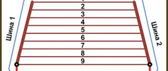
Structurally, the rear window heater is presented in the form of conductive strips through which current flows. This current causes these strips to heat up, resulting in heating of the entire glass, which means defrosting the ice and eliminating fogging.
The heating circuit includes not only conductive strips, but also relays, wiring and a fuse. To turn on the device, a button is installed in the interior of the VAZ 2107 car. To understand how the design of this device works, below is a diagram that shows in detail all the components.
In the diagram, each element has its own purpose:
- A mounting block or relay and fuse block is a device that houses a relay with two fuses inside.
- Relay - helps to reduce the current in the circuit, thereby eliminating overheating of the wiring and failure of the power button.
- Ignition switch - a positive contact comes from the lock, which eliminates the possibility of turning on the rear window heater when the engine is not running.
- The button is dual-mode - turns the device on and off.
- The warning light is an indicator indicating the operation of the system and is located on the dashboard.
- Heater - has the form of conductive strips or threads that are glued to the glass on the inside.
Knowing the circuit diagram of the device, it will not be difficult to eliminate various malfunctions. We will consider below what types of malfunctions most often occur in the rear window heating system of the VAZ 2107.
For what reasons does the heating not work?
Owners of sevens know all the “sores” of this domestic vehicle, so when a malfunction occurs with the rear window heater, you don’t have to look for a breakdown for long. However, beginners and those who have not yet encountered such a malfunction are wondering how to check the system to find the cause and the faulty part.
The following reasons are identified for the inoperability of the heated rear window of the VAZ 2107:
- The fuse is faulty - if, when you turn on the rear window heating button, you find that it does not light up, then the first thing you need to check is the serviceability of fuse F7. It is he who most often burns out, which leads to the inoperability of the system. The reasons for its burnout are known - the passage of a large amount of current.
- Malfunction of the rear window heating relay - the relay, the main purpose of which is to reduce the current supplied to the power button, can also fail. If it malfunctions, it will need to be replaced.
- Malfunction of the power button - the reason for its failure is oxidation or carbon deposits on the contacts that occur when turned on. After all, it is known that when the rear window heating is turned on, a current is generated whose value is ten times the nominal value. This phenomenon contributes to the formation of carbon deposits on the button contacts.
- Damage to conductive threads. The cause of their malfunction is a broken contact. However, any breakdown in the system can be eliminated if the cause and location of the damage are correctly identified.
So, if a fuse, relay or button fails, then these parts cannot be repaired and must be replaced. Damage to wiring is extremely rare, so it can only be called when all of the above elements have been checked.
Heating restoration
The reasons for the rear window heater not working on the VAZ 2107 are known, but many do not know why the conductive strip may break. The reason is somewhat trivial - too zealous washing of the glass surface or incorrect application of the tint film. Even if this happens, you should not despair, because you can always repair the heated rear window of a VAZ 2107.
First you need to find the location of the damage, as sometimes this is very difficult to do. If the location of the damage is visually traced, then such damage can be eliminated using a special “Kontaktol” repair kit from Keller or analogues. Its cost is about 400-600 rubles, and you can find it in any auto store.
ESP diagram VAZ 2110, 2111, 2112
- 1 – mounting block
- 2 – ignition switch
- 3 – right front door power window switch
- 4 – right rear door power window switch
- 5 – electric window motor reducer of the right front door
- 6 – electric window motor reducer of the right rear door
- 7 – electric window motor reducer of the left rear door
- 8 – electric window motor reducer of the left front door
- 9 – left rear door power window switch
- 10 – left front door power window switch
- 11 – relay for turning on electric windows
- A – to power supplies
- B – to the instrument lighting switch
- C – conventional numbering of plugs in power window blocks
The power window relay for this car is located in the mounting block. On the left under the panel in the fuse box on the additional connector.
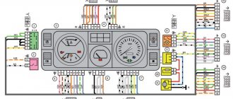
Wiring diagram for a VAZ 2114 car
Electrical wiring components
A single-wire circuit (used for all electrical wiring) has negative terminals of the consumer and the source, which are closed on the car body. The VAZ 2114 body is the second connector.
Complete circuit with electronics in VAZ 2114
Electrical wiring includes the following components:
- Block headlight.
- Anti-fog headlight.
- Temperature indicator.
- Mounting block housing.
- Electric fan motor in the engine cooling system.
- A block connected to the ignition system wiring group.
- Engine compartment light switch.
- Rear wiper motor connector plug.
- Devices.
- Car signal connection block.
- Electric motor for windshield wipers.
- Loudspeaker signaling device (SSU) housing.
- An indicator showing the volume of water in the glass washer.
- Front brake pad mode indicator.
- Oil quantity indicator.
- Generator and starter housing.
- Reversing headlight switching device.
- Lubricant pressure warning light indicator.
- Windshield wiper gear motor housing.
- Light housing under the hood.
- Engine coolant temperature indicator. 2x h16
Circuit breakers
In fact, the VAZ 2114 wiring is always connected to fuses. Such fuses do not protect only the circuit of the generator and charging device, the mechanism for switching on the power unit of the machine, as well as the winding of the backlight cut-off relay.
Before replacing a failed electrical circuit fuse, you need to find out exactly the reasons for the wiring overload, as well as its elimination. Finding the cause will be much easier if you first read the following materials. Below is a list of fuses and their purposes.
The data (the name of the fuse and the electrical circuit protected by it) shows a complete list of all possible wiring fuses. For each car, their number may differ.
- F1. Wiring diagram for the rear fog lights, electric motors for the headlight wipers, housing for the control lamp and its shutdown, electric motor for the headlight cleaner.
- F2. Turn signals and turn signal relays, hazard warning lights, hazard lights.
- F3. The wiring of the lamp illuminating the interior is customized depending on the personal preferences of the car owner, the ignition switch light, the car trunk light, the engine functionality check indicator, the on-board computer, the brake light indicator, and the clock.
- F4. A plug for connecting a portable lamp, a plug that connects the heating of the stern and rear windows.
- F5. Connection diagram for SGU, radiator propeller electric motor, VIP signal relay.
- F6. Power window relay, power window connection circuit. Fuse box in VAZ 2114
- F7. Wiring of the electric motor of the VAZ 2114 stove, electric motors for the headlight wipers and windshield washer, cigarette lighter circuit that illuminates the glove compartment, light bulb, relay for connecting the aft glazing heater winding.
- F8. Wiring diagram for the right fog lamp.
- F9. Left fog lamp diagram.
- F10. Electrical wiring for the side lights on the left side, an indicator that shows whether the side lights are on, a circuit for the engine compartment lamp, illumination of license plates, heating system levers and ashtrays, a cigarette lighter, a circuit for illuminating the switches.
- F11. Side lights located on the left side.
- F12. Right low beam design.
- F13. Left low beam design.
- F14. High beam device and left bulb. It is also an indicator for switching to high beam.
- F15. Right high beam design.
- F16. Wiring of turn signals, hazard light relay, relay responsible for the state of the lamps in the headlights, rear traffic indicator, lights signaling the following: low oil and brake fluid levels, whether the parking brake is on, low battery charge. Also a clock, an on-board computer and a generator excitation winding circuit during the start of the power unit of a VAZ 2114 car.
In addition to all the fuses listed above, which are located in the mounting block, there are 3 fuses. These fuses are located under the magazine shelf. The controller and relay circuit are also located here, with the help of which the VAZ 2114 power unit is controlled.
Window lifter diagram for VAZ-2115, VAZ-2115
Power windows for front doors for VAZ-2115, VAZ-2114 cars (usually power windows are installed only on front doors).
1 – mounting block; 2 – power window switch for the right front door; 3 – gear motor for the electric window of the right front door; 4 – motor reducer for the electric window lifter of the left front door; 5 – power window switch for the left front door; 6 – ignition switch; K5 – relay for turning on electric windows; A - to power supplies; B - to the external lighting switch.
Installation and connection of electric windows on a VAZ 2110
Electric windows have greatly simplified life for car owners and increased the level of comfort while using the car. The devices are controlled by a single button, which allows you to adjust the opening of the side windows, taking into account the current situation, and without the need to rotate the handles. The downside is that such a mechanism is not installed on all VAZ 2110 cars, but only in some modifications. But this drawback can be corrected by installing window lifters yourself. We will look at how to do this correctly in the article.
How to choose a window regulator for a VAZ 2110
If you are planning to install and connect window regulators yourself, start by choosing the appropriate device model. The key criterion when choosing is reliability. The installed product must perform its functions for a long time and work without failures. Finding suitable options in the modern market is not difficult:
- Slat mechanisms are window lifters that are not easy to use.
- Traditional designs. The advantages of these products include ease of installation and affordable price. Disadvantages - small service resource (when compared with other types of competitors).
- Rack and pinion windows. Such mechanisms are in greatest demand. They are considered the most suitable and are the most reliable.
Connection diagram for ESP power button
Contacts 1-6 and 7-3 are normally closed (NC). 1-2, 7-2 - normally open (NO), respectively. That is, 2 pairs of switching contacts. When you press the up button, contacts 1-6 open and 1-2 close (window rises). When you press the down button, contacts 7-3 open and 7-2 closes (window down).
Useful: VAZ-2113 diagram
Lada 2110 Carburetor › Logbook › Installing power windows on a VAZ 2110
I would like to save money when installing window regulators. I'll tell you how. So: The window regulator for 2110 costs 1,500 rubles for the front assembly and 1,600 rubles for the rear. Total - 3000 front + 3200 rear = 6200 rubles + installation.
We buy the following: 2 powerful motors for 750 rubles per front. You can do it cheaper, but the front ones are driven more often and would need more power. = 1500 RUR 2 engines "Kalina" x 450 RUR = 900 RUR 2 trapezoids x 250 RUR front bare (without motors) = 500 RUR 2 trapezoids x 250 RUR rear bare (without motors) = 500 RUR 8 bolts of the "receiver" - that's what through threaded rods with a 6-sided boss of 2 washers and elastic inside x 15 RUR = 120 RUR 1 block of buttons 4 pcs. = 120 rub. 16 meters of installation wire for 4 squares of copper stranded soft x 15r = 156r It turns out 3796 rubles. 35% cheaper. We also need door trim pistons. After much torment, I installed the Prirovsky ones. They hold up better than standard hedgehogs. Before installation, we assemble the station - insert the square of the motor drive into the fitting boss. CAREFULLY! The lug with the cable tries to jump away! If the cable unwinds, it will take a long time to insert it back with mats. It’s better to open the engine, coat the gasket with sealant (if there is one) and just coat the space under the gasket (if there is none) and thoroughly hammer the grease onto the worm. It is better to lubricate not lithol or grease, but CV joints. The one that doesn't freeze in the cold. Spray the brush assembly well with silicone grease. Not thick! And not VD-40. We attach the motor to the fittings with the same receiver bolts.
Installation is simple: 1. Remove the door trim. 2. Lower the glass 3. Unscrew the window regulator. 4. We thread it outwards. 5. Install the motor. When installing, you can slightly tighten the glass fastening. Because the glass gets a little warped in the frame and gets stuck. And if you make them a little looser, the glasses themselves find the right position and become as they should without jamming. 6. All holes match, no need to drill anything. 7. We stretch the wires through the door. 8. We check the installation by connecting to the battery (I check by connecting a screwdriver to the battery) 9. I stretch the wires under the central tunnel to the gear shift knob. HERE I have a button block installed. 10. I pull the buttons from the nearest powerful wire fuse (4 mm). 11. Checking the polarity. 12. I close everything in place.
Note. Why did I use 4 square thick wires? And not just sniffles? The fact is that motors consume a lot of current. And there is a lot of heating of the thin snivells. In addition, due to heating, the voltage drops significantly. On thin wires - up to 2 volts. As a result, it closes slowly and eats a lot. On thick wires it buzzes SOOO quickly. Faster than many foreign cars.
Serial connection - diagram
We connect the output of additional button 1 in the driver's door to input 6, and output 7 to input 3 of the main button on the passenger door. We cut the wires in the block connecting contacts 5-6 and 6-3. The minus of contact 5 now goes only to the backlight, and contacts 6 and 3 now take output from additional buttons 1 and 7 of the driver's door. Installation in parallel will result in short-circuiting during lifting and lowering. Power wires are highlighted in bold.
When using trigger buttons, connect all ESP motors only through a relay. When using a conventional door closer, relays are also needed, since they are not in the long-press closer block and all the current flows through the buttons and wires from them.
Window lifter options
According to their design, electric windows (ESP) are divided into three main types:
- rack and pinion window lifters. The devices are not very powerful, plus they require systematic lubrication. If this is not done, their service life is significantly reduced;
- Cable window lifters. Their main advantage is their low price. In addition, changing the motor on such a window lifter will not be difficult (since it is easy to find on sale). They are inferior in power to rack and pinion lifts, which is especially noticeable when the glass freezes to the door in winter;
- finally, the windows are lever operated. Among car enthusiasts they are considered the best option: powerful, fast and almost silent during operation. These are the ones that will be discussed below.
The most popular among lever ESPs are the “Granat” lifts. Their popularity is due to two factors: a fairly affordable price and good equipment. Along with the ESP, the driver receives wiring, fasteners, cuffs and plugs.
Lever window lifters "Granat"
Parallel connection - diagram
Wires from the main button next to the driver's ESP motor go directly to pin 88 of the relay and from pin 30 directly to the engine, and long wires from the backup button go to pin 85 of the relay winding, and the relay feeds a powerful plus to the passenger's ESP motor. A parallel connection for power buttons is preferable, since there is no need for a relay on the main (passenger) button, thereby eliminating unnecessary relay clicking when the main button on the passenger door is operating.
Troubleshooting procedure
- Check fuses F8 (20A) and F8 (20A) (mounting block).
- We check the serviceability of the rear window heating button. Is there a “plus” on pin No. 10 of the switch button and after turning on the button on pin No. 9 (a test lamp or multimeter will be useful).
- We check 12V at the output Ш5-2 and at the connector near the rear window.
- We check the wires and their connections.
- We check the rear window heating relay - K7.
- We check the integrity of the glass heating filaments.
The algorithm for determining the cause of a malfunction is similar for most cars, the only differences are in the names of fuses, relays and connectors.
By the way, do you know that to extend the service life of the heating elements, they use a Glass Heating Regulator (DOC), and you can also install a Fresnel lens on the rear window?
Source
Scheme for any number of buttons and doors
Here you can place any number of buttons in parallel and simultaneously press them in different directions - a short circuit is impossible from the circuit design. In a situation where we press the up button on the main button, and the down button on the backup button, it will simply stop, since both power lines will have the same potential. The advantage of the circuit is that the power switching is in one place, there are no losses in the harnesses and on the buttons, there is a minimum of “pulling” of wires - 2 in total per channel + ground.
Standard windows
On domestic cars of the “classic” family, only manual power windows were installed. For example, the first “sevens” had rack and pinion ones, and the “nines” and “kopecks” had cable ones. Why were such mechanisms installed? It’s just that domestic designers tried to reduce the cost of the car, so for the sake of economy, devices with plastic gears were installed. And they fail quite quickly.
In the early 90s, the designers who developed the “sevens” realized their mistake and began installing cable-operated windows on the cars, but the drive was still manual. The peculiarity of such structures is that they are repairable. If in rack-and-pinion gears when a plastic gear breaks, the entire mechanism needs to be replaced (and it is very difficult to find it on sale), then if the cable system malfunctions, it is more than possible to carry out repairs.
The principle of operation of all mechanisms (both cable and rack and pinion) is the same - the system on which the glass is attached rotates with a handle. Depending on the type of window lifter, either the gear moves along a toothed vertical rack, or the cable is tensioned.
Glass closer Pandora DWM
Connection diagram for the passenger door button in series through a duplicate button on the driver's door. Contacts 1-6 and 7-3 are always normally closed. When you press the up button, contacts 1-6 open and 1-2 close (window rises). When you press the down button, contacts 7-3 open and 7-2 closes (window down). The 30th contact of a 5-pin relay, without supplying voltage to the winding contacts, is constantly shorted to contact 88, which gives us the necessary negative contact (works like a switch). If voltage is applied to the winding, then contact 30 is disconnected from contact 88 and connected to contact 87. Contact 86 of the winding is connected to ground.
How to connect a duplicate power window button
When installing window lifters, the question arose: where and how to place the control buttons so that all passengers would be comfortable, and the driver could freely control all the window lifters. As a result, I installed it on the door, as shown in the photo:
I tried to put in a ten point block, but it didn't get too wide. The individual buttons are easy to insert if you remove the rectangular adapters for standard sockets. On the other doors there is a corresponding button.
I'm a non-smoker, so I don't need an ashtray, so I sacrificed it for the convenience of opening and closing the windows.
Remove the plastic and mark the holes for the buttons. Then we take a screwdriver, insert a drill and make a rectangular hole around the perimeter for the buttons, measure and edit with a file. We install the buttons, observe how and what happens to the ashtray, take a hacksaw (I did this with a grinder) and cut it together with the seat saddle into which the ashtray itself is inserted, then screw the ashtray into the saddle mount with a self-tapping screw, insert it into place and get a fake ashtray.
Convenient and practical.
My buttons are installed like the Landniver's, but they don't interfere with the ashtray. So the whole operation to amputate part of the ashtray is completely in vain. 10-sided buttons with pads. The installation took about an hour. So smokers can safely use these necessary things (both ESP and ashtray).
The most convenient place for window buttons (as it seems to me) is on the gear shift tunnel liner, like the Landniver. I put them there:
The only difference is that I got the buttons from Volga. They are half as long. And therefore they can be removed away from the ashtray. True, I had to abandon the pads. Each plug is inserted separately. As a result, the buttons are where they are needed and the ashtray is intact.
Update from 02/19/06, author: aal.
The surcharge applies to citizens who have small children or want to have them.
American statistics show literally dozens of accidents involving a simple situation: a puppy, left in a stationary car, stuck its head out the window and accidentally pressed the window-up button on the armrest with several paws - front or back. The result is fatal as it takes very little time and force to block the arteries in a thin neck.
Accordingly, the recommendation: it is advisable to place all buttons on a vertical surface so that they cannot be accidentally pressed and require a conscious effort. Instead of an ashtray, I have the right door button “cold welded” glued into the hole from it; The left door button is cut into a hole on the lower surface of the dashboard, near the headlight handles and the dimmer hydraulic corrector. The general logic of the installation was approximately the same as that of previous authors: the right button should have been accessible to everyone, the left button should have been accessible only to the driver, and he was too lazy to create additional electronic components.
At the same time, instead of an amputated ashtray, a safe niche was created for a rechargeable mobile phone. It doesn't fly anywhere.
Update 05/12/06 from Kotya.
Everything is clear from the photo, no comments needed:
Window control from the rear seat
So that passengers sitting in the back seat could independently regulate the flow of wind to them, in addition to the power window buttons in the “beard,” I inserted buttons on the left and right trim, above the ashtrays. Just in case, there is only one suitable window. Make a rectangular hole 25 * 38mm for the button.
You will need: two power window buttons with faceplates, covers for them (with inserted wires or 14 narrower terminals), a two-core cable 10 m long, four five-pin relays, a set of electrical terminal blocks (translucent, 2.5 squares) or three three-pole ones clamps, pieces twenty wide and a couple of meters of solid wire.
The power window button has two groups of contacts. Both groups have three contacts, and one of them is an “input” that is shorted to a normally closed “output”. When the button is pressed up, the "input" of one of the groups is shorted to a normally open "output". And when you click, the same thing happens in the other contact group.
The motor is connected to the "inputs". Zero is supplied to the normally closed “outputs”, and +12 V to the normally open ones. Thus, the engine is constantly connected to the “ground” and only during operation is “plus” supplied to one or another of its outputs. (I didn't know the logic behind the button and didn't look ahead. It cost me an extra half day of work after creating the first version.)
In addition, the button has a contact for connecting the backlight.
Here are the connection diagrams:
Therefore, the following circuits are connected to the button terminals: Terminals 3, 5, 6 - ground", Terminal 1 - motor up, Terminal 7 - motor off", Terminal 2 - +12 V, Terminal 5 - backlight power.
In order for the two buttons that control the motor not to conflict (after all, when you press one of them, it supplies “more” to the motor, and the second still maintains “ground” on it), it was necessary to include four relays with five contacts in the circuit, one for each wire of each motor. (Here are my extra half days! Shouldn’t I have scattered everything in half?) These relays are installed inside the “beard”:
I removed the power windows from the free fuse and inserted them into the “beard”. The backlight is turned on by one of the standard buttons. Next, I laid two bundles of four wires each on the additional buttons (the bundles have two wires from the motor, backlight and +12 V). The “weight” of additional buttons is taken next to them. All cable connections (and there are some) are made using electrical connector blocks on
The circuit diagram looks like this (only half is shown, for example the right one :)):
The main thing is not to press the buttons on one side at the same time during operation! (Although in the first version I assembled, nothing was burning. And the glass also moved, but slowly, slowly. I still didn’t understand what the joke was).
A duplicate window control key is installed in the space between the main button and the gear motor (the contacts are marked in yellow in the figure). You can link any number of repeating buttons.
In the normal state, both outputs of the electric motor are equipped with a “casing”, the glass is in place. When you press any key, +12 V will be supplied to one of the terminals, the glass will lower or rise. In the event that a mutually exclusive action on both keys is selected, nothing bad happens: +12 V is supplied to both outputs of the electric motor, and the glass, as in the first case, stops.
Update 06.06.08 from Vader
I don’t mind the ashtray either, because I don’t smoke either, but the location in the Niva is not very convenient, so the controls located nearby will also not be very convenient. I placed the buttons in the standard panel slots, moving the headlight key to the bottom row. This arrangement seems to me the most convenient and no changes are required. In addition, the ESP also comes with a sufficient number of cables:
When you need to install ESP (power windows) yourself, then, as always, it is difficult to find correct and understandable diagrams on the Internet for everyone. Having experience in electronics for everyone, I am publishing correct and understandable connection diagrams for ESP, a smart door closer Pandora DWM-210 (but it is better to install a PWM-200 Sheriff), as well as simple latches only for lifting the glass, installed in a broken wire on the plus side of the motor.
The installation process of my ESP is described in detail by me here: www.drive2.ru/l/4651635/
Let's take the power buttons from (NOT low-current (multiplex) from Itelm), namely the power buttons: blocking from Granta and the button from Kalina of the new model. (power), as they are the most attractive in appearance... These are, of course, not dual-mode import buttons, but they will also work with the smart closer. We also install the closest type PWM-200 Sheriff. The power buttons can be easily identified by their contacts - they have thick, flat spatulas, while the activation buttons have needle-thin pins! Power cables (shown in bold on diagrams) are >=1mm2 thick and control cables can be thin=0.5mm2.
Exception! If the buttons are not on the door, but on the center console, and thick wires >= 1.5 mm2 are stretched from them to each door, then you can do without a relay, since there is no duplicate button here, and each connection and removal are minimal. Then you don't need to read any further.
Plus + 12V must be taken from the fuse box, and not from the ignition switch, otherwise the automatic window closer will not work when inserted. It is better to take the weight from the bolt behind the mounting block, and not in the door, since the contact in the door may not be very good. Even if the door contact is good, even if the car is not old. Buy canned terminals.
Wiring diagram for power window switch “AVAR”
Connection diagram of the backup button on the driver's door to the main button on the passenger's door When two buttons are installed on the window regulator, they are usually installed in series (or in parallel, but then they are necessarily disconnected via a relay).
The main button is the button that controls the power window of the door on which it is installed. The duplicate button is a driver's button that additionally controls another power window from the driver's seat.
Daisy chain connection (for low current buttons) The output of the driver's door auxiliary button 1 goes to input 6, and the output 7 goes to input 3 of the main passenger's door button. We cut the wires in the block connecting pins 5-6 and 6-3. The minus of pin 5 now only goes to the backlight, and pins 6 and 3 now accept the output of additional buttons 1 and 7 of the driver's door. Attention! Parallel installation will cause short circuit when raising and lowering. Power cords are shown in bold.
Parallel connection (for our power buttons) Since with a serial connection you still can’t do without a relay, it is better to do the button duplication circuit in parallel, decoupling the main button from the backup button through two 5-pin relays: the wires of the main button next to the driver’s ESP engine go directly to The 88th relay contact, and from contact 30 - directly to the engine, and the long wires from the duplicated button go to the relay coil contact 85, and the relay already gives a powerful advantage to the ESP of the passenger engine. It is preferable to connect the power buttons in parallel, since the main button (passenger) does not require a relay (the wires are short here), and thus we eliminate unnecessary pressing of the relay when pressing the main button on the passenger door. For weak low current (trigger) buttons, in this case you will definitely need to use 2 additional relays to discharge the passenger button (which is why a series connection is always used for trigger buttons). Also, everywhere in my circuits a parallel connection is used, since all the buttons are powered.
Wiring diagram for multiplex ESP button (low current
Connection diagram for ESP when contacts are connected to ground using a multiplex button
Dimensions of the installation location of the ESP “AVAR” buttons
Close Pandora DWM-210 glass
What does this give: - full stroke of the cup for a short press (“one touch”) - BUT DOES NOT WORK FOR 2 CUPS AT THE SAME TIME (since the module has only one sensor for electromagnetic noise of the motor, current and time); — glass stopper in any position by repeated pressing in any direction; — automatic glass stop when meeting an obstacle in the window opening; — automatic shutdown of ESP motors due to current overload; — automatic closing of windows when arming the car; — automatic opening of windows when disarming in the pre-arming position, if the stop lasted no more than 20 minutes. (The tachometer works quite conditionally and may leave the windows closed or not close them). The closest one is installed in the driver's door. ATTENTION! When the button is held down, the nearby one doesn't use its relays, which take more (via a 20A fuse) and less from the nearest one, but send all the current to the motor directly from the button, so you need to insert a relay after the button exits with long wires! Apparently this was done so that if the one closest to it fails, you can always close the window by simply holding the button. When you briefly press the button, the door closer with its relays is activated and brings the glass up. Place the relay only on the input of the closer from the output after the duplicated button! If this is not done, the passenger window will barely move due to the master keys along the long wires of the sequential connection of the buttons. The output of Nearest must be connected directly to the motor without a relay, otherwise the motor electromagnetic noise detection will not work and Nearest will not work! There is no need for a relay at the output of the driver's power button, since all the power cables there are short. It is ideal to install 2 closers on each door, as is usually done on foreign cars - then the AUTO mode will be on 2 doors at once in parallel, and not alternately. Also, you won't need to run 2 extra thick wires to the engine from the driver's door to the passenger's door. I would immediately understand that the Pandora DWM-210 is such a Ketai g**, but without its relay in the power section of the nearest one, I would buy and install a Sheriff PWM-200 window regulator, where the power compartment is clearly separated from the control compartment and, in addition, two glasses can be closed at the same time with one touch! That is much better!
The power windows are activated by the module sequentially after a trigger pulse is given: first the driver's door, then the passenger's door, and the next channel is activated after processing the previous one. If the glass is already closed, the module will immediately switch to the next channel. Closing is controlled by electromagnetic noise from the motor.
When turning on the power, the nearest module must be calibrated for the protection trip current. It is necessary to lower each glass with a SHORT force until it stops, and then lift it in the same way. In this case, the closest one stores the engine characteristics. The command signal for closing and opening is NEGATIVE ONLY. Control can be carried out both from the central locking and via an additional alarm channel. The control output of the security system must be connected to the module terminals “White / Red” (window up) and “White” (window down), respectively. The duration of the starting pulse must be at least 500 ms. (0.5 sec.).
Attention: for old problems, the wires of the buttons and motors are mixed up - for such blocks we change the wires under the numbers: 9 2, 16 20, 15 10, 14 19, 13 18. On the latest Pandora (November 2011 and newer) the circuit is working properly, so there is no need swap wires from buttons and motors!
Wire break closer ESP type Convoy CL-200 for lifting Appendix dated 10/05/2014 upon request of SIBUR95
There are door closers like Convoy CL-200, which are connected to a break in the rising wire going to the ESP motor. There are 2 wires from the nearest one (input and output) and they are constantly closed in it. When the closer is turned on, they break, and on the weekends a plus + appears. On GREEN, when the door closer is operating (arming), a plus appears and goes to the motor, and a minus goes from the button (or from the relay from pin 88 to 30) to the motor. When the closest one fails, it simply switches the current from BLUE to GREEN with the relay closed, and that's it.
Here the circuit differs only in that the minus of the motor is connected directly to the button (or to the relay, if the button is duplicated), the plus also passes through the nearest one, and the relay is only at the INPUT of the closest one, which does not interfere with the detection of engine noise.
You can also make a circuit for duplicating buttons not in series, but in parallel on two 5-pin relays. The advantage is that the series circuit is eliminated, the relay will no longer click from the main button, which is closer to the engine (with short wires), but only from the backup one. The downside is that for non-power-on (trigger) buttons in this case you will need to use 2 additional relays (relays 3 and 4 in the diagram).
Circuit for any number of repeating buttons and number of ports
You can place as many buttons as you like in parallel and simultaneously press in different directions - a short circuit is impossible! In a situation where we press the lift on the main button and duplicate the lowering, it simply stops, since both power lines will have the same potential. The only difference between the closest ones is the presence of a microcontroller between the buttons and the power relay. The advantage of the circuit is that switching of the power supply occurs at one point, there are no losses in the beams and on the buttons, there is a minimum of “pulling” of wires - only 2 per channel + ground. In solid and complete door closers, the power part and control lines are implemented in the same way + the functions of “automatic detection” of active control levels have also been added.
If PWM-200 is installed on the nearest Sheriff type with low-current control, then there is no point in these relays, since they are already installed in the nearest one. This relay circuit is used to understand the essence of reverse control and parallel duplication of buttons. In this way, power outputs are implemented both in the central locking system and in the door closers.
It is also recommended to connect 22uF 25V non-polar electrolytic capacitors to the terminals of the ESP motors to smooth out the range of current ripple in the nearest power channel so that it works correctly even when the motors were worn out and did not suddenly stop the glass when opening and closing.
Typical diagram of duplicate buttons for 4 doors. Duplicate buttons must also be integrated with two 5-pin relays (they are not on the diagram).
This article provides a brief overview of installing an additional window lift button in the doors of VAZ models. To install such a key and connect this option, we will need: the ESP button itself, a wire (about 9 meters), a lock for the button, two large socket terminals and the same two large socket terminals, 7 small socket terminals, a ground terminal, bearings for each of the terminals, as well as plugs for fastening the door trim and plastic clips.
In principle, if desired, the standard ESP control buttons on models 2112-2110 can be replaced with keys from Kalina or Priora, but they cannot be activated, and they must be high-current.
We don't need to reinvent the wheel or rediscover America, we will connect according to the existing scheme (see diagram above).
The first step is to find the electric drive relay. This relay should be located in the fuse box at the top of the fuse block. If several relays were detected at this location at the same time, then we need to determine which one we need. This is quite simple to do, turn off each relay in turn and check how the window regulator works. When it stops working, we have found what we need.
After removing it from its normal position, disconnect the negative terminal from the battery. The next step is to disconnect the relay from the housing. This can be done with a thin flathead screwdriver, you need to slowly press the latch, then push down on the housing, after which the latch will slide out and the relay can be removed.
So, we need to find the white wire through which the black stripe runs after turning on. You need to connect a 12 V cable to it. Now we need a mass that can be picked up from the door. The problem is that the contact will not be reliable, so it is better to take the ground from the bolt, which is located behind the mounting block, and connect the negative wire to it.
Now we need an advantage, which we take from the backlight, connect, for example, to the white wire of the ashtray backlight.
Next, we pull all the strands towards the door, passing them inside through the corrugation. Stretching it, we connect it to the window regulator and then to the button. To get inside the doors, you must first remove the trim.
Finally, a video review that presents the original Italian SPAL ESPs, which are installed on both doors. Such windows can be ordered without problems in online stores.
Related posts:
- Autostart turns on the ignition but does not turn the starter
- The upper arm of the VAZ 2107 is loose
- VAZ 2115 does not respond to the ignition key
- Placing timing belt marks
Installation of electric windows on a VAZ
The procedure is performed in the following sequence:
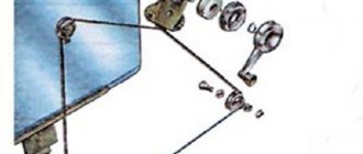
- temporarily remove the glass seal located on the inside of the door;
- remove the glass, and then dismantle the window regulator fastening mechanism;
- we install devices that will operate from an electric drive;
- connect the negative terminal to the battery and check the operation of the new window regulator;
- We install the glass in place and trim the door.
Unlike conventional mechanical devices, power windows are not equipped with traditional gear reducers, but with a special drum. The shaft of a DC electric motor is inserted into its hole located in the center. In this case, the motor is only a component of the gearmotor, on which, as we found out earlier, the speed and quality of raising and lowering the windows depends.
Installation of the lifting device is quite simple. It starts with disconnecting the battery. After this, use a curved screwdriver to unscrew 3 screws, unfasten the door trim latches and remove the door pocket. Using a thin screwdriver, pry off the handle (latch) of the window lifter - the tip of the tool is inserted into the recess between the latch and the socket.
The handle itself is removed. At the next stage, the car door opening handle is dismantled. To do this, use a screwdriver to pry the handle cover and remove it. Now use a screwdriver to remove the 2 fastening screws that were hidden by the cover plate. After this, the handle can be removed without much difficulty. Using a screwdriver, you can also remove the power window button, which serves to lock the door.
After removing 6 pistons, the trim covering the car mirror adjustment mechanism is also removed. As a result, it remains easy to dismantle the door trim. Armed with a 10mm wrench, unscrew the 2 bolts that hold the auto glass clips. Next, 2 nuts securing the lifting mechanism, nuts of the upper and lower fastenings, and 3 nuts securing the lifting mechanism are unscrewed in sequence.
Upon completion of the described stage, it is time to remove the lower guide pin of the lifting device from the door panel. To facilitate and simplify such an operation, the upper pin of the guide must be bent using a screwdriver. Now the entire lifting mechanism can be safely removed through the resulting opening in the door frame.
Replacing the window regulator
If the VAZ-2114 window regulator does not work, it can be replaced with a new one. To do this you need to do the following:
- Using a 10 mm wrench, unscrew the three nuts that hold the glass guide.
- Using a size 8 wrench, unscrew the three nuts that secure the electric motor or manual drive gearbox.
- Disconnect the glass mounting bracket from the glass holder. To do this, you need to unscrew the two 8mm bolts on the bracket.
After this, you can pull the window regulator out of the door. The glass must remain raised. Otherwise it will be impossible to remove the mechanism.
The new lift is installed in the reverse order. However, there is no need to rush to tighten the glass mounting bracket. First you need to make sure that the glass is in the correct position in the guides and moves clearly in them.
Types of window regulators and the main causes of their breakdowns
Today the following types of window lifters are in use on VAZ:
- rack type (experts consider them the most reliable of all known designs);
- cable;
- plank.
Depending on which company produced the product in question, it can be installed in the car door as standard, or, if it does not fit in size or other technical characteristics, it can be altered without unnecessary problems.
Since both domestic and imported gear motors can be installed on the lift, the described devices, depending on the type and origin of the electric motor, may differ:
- by the speed at which the glass is raised or lowered;
- according to the noise level recorded during operation of the window lifter;
- if possible, its normal operation in winter conditions.
The parts in question can fail for a number of reasons, which can be summarized into two main groups: mechanical and electrical failures. The list of possible reasons looks like this.
- The whole design doesn't work. The cable has broken or become jammed. Lifting mechanism malfunction.
- The electric motor failed due to moisture getting into it. Such a malfunction occurs quite often, since the gearmotor has a leaky housing into which water leaks, which is why rust forms inside the device over time. As a result, spreading corrosion destroys the entire mechanism.
- The power window relay has failed. The performance of this component can be determined by replacing the problematic relay for testing with a guaranteed working one.
- The corresponding fuse has blown. If after installing a new element the device starts to work, then this is the reason. If the new fuse blows again, you need to look for the short circuit.
- Short circuit in the circuit. Its location is determined by which fuse burns when turned on. The cause of this malfunction can be either burnt out wire insulation or a failed gear motor or mechanism switch.
- Breakage of the switch. Determined after replacing the problematic one with a new, known-good switch.
- Break in the common circuit. This can happen due to a mechanical break in the electrical wire, disconnection of the block or poor contact in it.
What causes mechanism failure?
The reasons why problems arise in the operation of the window regulator can be divided into two large groups:
- Mechanical.
- Electrical.
The most common ones are listed below:
- Changing the position of the glass or its distortion.
- Failure of guides.
- Drive wear.
- Violation of the integrity of the cables.
- Closing the circuit.
- Oxidation of contacts.
- Failure of functional elements, including the ESP button, the adjustment of which will require theoretical knowledge of pinouts.
You can entrust repairs or replacement of components to specialists or do it yourself.
Power window
The vehicle configuration with electric windows contains additional bundles of wires that make up the VAZ-2114 window lift circuit. In addition, there is a control button on the front passenger door trim. On the driver's door there is a block of buttons that control all windows that have an electrical connection for the VAZ-2114 power windows.
The scheme has the following elements:
- Mounting block.
- Front passenger door ESP button.
- Front passenger door lift motor.
- Driver's door ESP electric motor.
- Driver's door switch button.
- Egnition lock.
The letter “A” in the diagram indicates the wires going to the power supply of the circuit, and the letter “B” indicates the wires going to the side lights.
Window lifter.RF › Blog › Replacing the rear windows of the VAZ-2110
This report on the installation of electric windows in the rear doors of a VAZ-2110 was prepared by our buyer Andrey Aleksandrovich Serebrennikov from Sevastopol, as part of his participation in our promotion.
And finally the long-awaited rear electric windows have arrived.
It all starts with removing the door card. We unscrew everything that can be unscrewed, and then pull off the card with the pistons, you just need to pull it off carefully, you can break off the leg under the pistons.
Then unscrew the 3 “8” nuts that hold the lowering lever, and the 2 “10” nuts that secure the guide to the door, be careful not to lose the growers!
Then unscrew the 2 bolts securing the guide to the metal base of the window.
Holding the base of the window with your hand, we take out the entire mechanism and place it at the bottom of the door, now we need to secure the window.
Since there was no stick at hand to support the bottom, an L-shaped wrench was used in this way:
Now the window does not try to move down, and will not interfere with us pulling the entire mechanism out.
We pull out the mechanism through the lower left hole of the door (for the left rear door), the whole difficulty lies in removing the mechanism block itself, since the pulley is very long and does not want to fit through.
Then I checked the power windows for functionality by connecting it to the wire going into the door and pressing the button so that I wouldn’t have to take it all back out later.
We begin to put the ESP inside the door. Compared to the stock one, I didn’t experience any difficulties; everything fits in quite quickly.
We begin to attach it all to the door. And then I discovered a small problem: there are only 2 fastenings of the ESP unit to the door and they are designed for nuts at “10”, while the standard ones were at “8”. It's good that I take it with me in reserve. In total, instead of 5 fastenings we get 4, but now everything is turnkey to “10”.
We check the functionality and fasten the card in place. And we are waiting for the deluxe 2 cards to arrive so that we can fully enjoy the view of the salon!
Lever window lift
One type of window lifting mechanism for the VAZ-2114, which, unfortunately, does not come from the factory, is a lever window lifter. These products are manufactured by Ningbo Stone.
These devices have proven themselves to be reliable and unpretentious mechanisms. Unlike cable window lifts, they have a greater lifting force. Glass frozen in winter is not a problem for them. They can handle them easily, while cable lifts experience significant stress on both the mechanism and the electrics.
One small disadvantage of the lever mechanism is that the speed of raising the glass is not the same. The higher the glass, the smaller it is. This is due to the geometry of the lifting mechanism. A good example would be scissors. If you take them by the rings and move the ends apart as much as possible, and then bring the rings closer to each other, it becomes clear that the height of the cutting ends changes faster when the rings are moved apart as much as possible. Conversely, the rate of ascent decreases as the rings move closer together.
It is this circumstance that allows this mechanism to create significant force. As we know from physics lessons, when you lose in distance traveled, you gain in strength. The same thing happens here: at the top of the range of motion, the distance traveled decreases and the lifting force increases.
The mechanism is driven by an electric motor and is connected as standard to the VAZ-2114 window lift circuit.