Reworking the low beam button
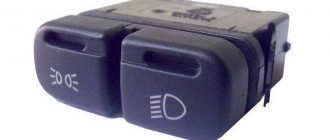
As already mentioned, the button for turning on the low beam and the button for the dimensions of the VAZ 2114 are combined and located in pairs. Their main drawback, which most car enthusiasts point out, is the absence of a power-on LED on the low-beam headlight button.
This problem is quite serious, since very often it becomes unclear whether the headlights are working or not (especially during daylight hours). You can solve this by upgrading the button yourself.
For this you will need:
Button redesign
The button modification should be carried out according to the diagram shown here. Resoldering the LED itself from one board to another is highly not recommended, since this requires a soldering station equipped with a hair dryer, a special flux and high skill in working with them.
First, we need to remove the main button from the car panel (how to do this has already been discussed above).
After it is removed and disconnected from the wires, perform the following operations:
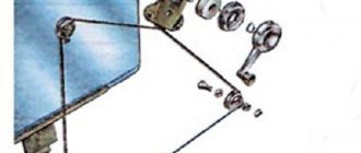
- remove the keys by prying them off with a flat screwdriver;
- we disassemble the body of the buttons by pressing the latches with a screwdriver (the buttons themselves at this moment must be in the “on” position);
- we see that the sidebar button has two diodes (backlight and indication), and the low headlight button has only a backlight button;
- remove a pair of legs and a pair of contacts from the donor button;
- we rearrange them into the free spaces on the working button;
- remove the board from the donor button with two diodes and insert it into the working button instead of the board with one diode;
- solder the board to the legs that were added;
- make a hole in the button cover (this can be done with a sharp knife or simply punched with a flat screwdriver).
Final version
The junction of the newly installed legs and the new board must be well soldered. Otherwise, the button may quickly fail or not work correctly.
After all these operations have been completed, all that remains is to assemble everything in the reverse order and install the upgraded button in its place (during installation, it is important that all the mini-latches on the case fall into place).
How to find the location of a broken glass heating filament
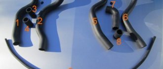
It is not difficult to determine which heater wire is in the reef, since fogging in the area where it passes does not disappear when the heater is operating. Therefore, in order to easily find a faulty thread during repairs, it is advisable to count the number of threads from top to bottom and remember which of them is in the break, so that then, during a visual inspection, try to find the place of its damage. But the thread break is so small that it is impossible to detect it visually. So a DC voltmeter, ohmmeter or voltage indicator will help in your search. To quickly find the location of a fault in the heating element, you need to imagine how it works and works.
The design of the heating element of the glass heating system
A natural question arises: why does it happen that only one or several threads in the heater do not work, while the rest work? To answer this question, you need to familiarize yourself with the design of the heating element.
The heating element of the rear window of a car is designed as follows. Two conductive bars 1 and 2 are attached to the sides of the rear window. Cores made of high-strength material are attached to these bars. Each wire has a resistance of approximately 10 ohms. The number of threads depends on the height of the glass. Thus, each wire is a separate heating element, the operation of which does not depend on the others. A parallel circuit for connecting heating elements is used. This circuitry ensures high reliability of the heating element, since the break of one or more wires does not lead to a complete stop in its operation.
Finding a broken heater filament using a voltmeter
To work, you will need any DC voltmeter with a measurement limit of 15 V. Any tester with a dial scale or a digital multimeter will be suitable as a voltmeter. Before starting work, you need to turn on the heating element.
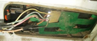
Since one of the heating element buses is connected to the car body, the negative terminal of the voltmeter can be connected to the car body; Any screw or bolt screwed directly into the housing will do. The alligator clip is more convenient to attach to the trunk lid lock bracket.”
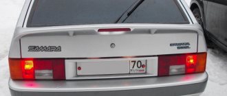
Since it is difficult to see visually with transparent glass whether the heating element is heating up, touching the positive probe of the voltmeters on bus 1, and then on bus 2, you will immediately understand. Bus 1 should be +12 V, and bus 2 should be 0 V. It's possible that your car's left bus is grounded and the right bus is energized. If the busbars are not accessible, measurements can be taken by touching any of the wires with a probe at the points of connection with the busbars, that is, where they exit the rubber seal. In the photo these are points 1 and 5.
Using a voltmeter it is easy to determine which part of the heating system is faulty. If the heating element is turned on, the power indicator on the button is on, and there is 12 V on bus 1, but there is no heating, then the wiring on bus 1 is OK. If there is no voltage on bus 1, it means there is a bad contact in the power supply terminal on bus 1, or the relay is faulty. If 12 V is present not only on bus 1, but also on bus 2, you need to look for a bad contact in the terminal for connecting the cable to bus 2 or in the circuit connecting the cable to the vehicle ground.
Finding the location of the thread break
After checking the heater power system, you can begin to determine the location of the heating wire break. The wire represents a tape resistance of about 10 ohms, so the voltage at different points has different values. Therefore, at point 1 the voltage will be 12 V, at point 3 - 6 V, and at point 5 - 0 V. Therefore, even without knowing which of the wires is in the break, it can be easily determined by measuring the voltage in the middle of the length of all threads . On broken wires the voltage will be 12 or 0 V. If the voltage is 12 V, the break point is on the left, and if 0 V, then on the right.
Now just slowly bring the probe to the break, instead of a sudden change in voltage, there will be a break. For example, in the photo this is a piece of thread between 6 and 7 points.
Finding a broken thread using an ohmmeter
Using a multimeter or pointer tester in resistance measurement mode “title =” How to measure “> you can also successfully find the location of the wire break. Grounding won't work.
If the wire break is unknown, you need to connect one end of the ohmmeter probe to the ground terminal, and touch the center of the heater wires with the other one in turn. The wire on which the ohmmeter shows resistance is twice as large and will be broken. For reference: the resistance of all wires in relation to bus 1 or bus 2 should be 2-3 ohms. If the filament breaks, the ohmmeter will show 4-6 ohms.
If a damaged wire is detected, it is necessary to move the probe tip from the center to any direction. If the resistance increases as the probe moves towards busbar 1, then the break occurs in the gap between busbar 1 and the contact point of the probe. For example, at the point indicated by points 1 and 2. As soon as the probe passes the gap, the resistance will sharply drop several times. If the resistance decreases, this means that a wire break occurs between the probe and bus 2. For example, at the point indicated by points 3 and 4. Then you need to move the probe towards bus 2, and when the resistance drops sharply, at that moment there will be a pause.
Locate broken threads with an automotive tester probe
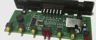
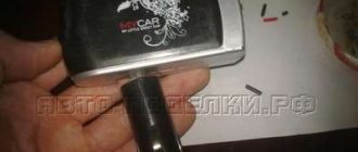
If you do not have a voltmeter or ohmmeter, you can find the break point of the heating element filament using a homemade automotive tester probe, consisting of a single LED and a current-limiting resistor. I made the tester for myself a long time ago, although I have measuring instruments. The homemade car tester is always in the glove compartment of my car, and I have had to use it more than once.
Detecting a broken wire using a tester probe is no different from searching with a voltmeter. The indicator in this case will not be an arrow or number, but an LED glow.
Before you start searching for a damaged filament using a probe, supply voltage must be applied to the heating element. First, the presence of voltage on bus 1 is checked, the LED should be lit, if the LED is not lit, then the error lies in the power supply circuit of the power supply. Next, the voltage on bus 2 is checked; the LED should not light up; if it lights up, it means the contact at the point where the wire is connected to the bus or housing is faulty.
To find where the heater filament breaks, you need to slowly, lightly touching the filament, move it along the end of the probe. At the point where the LED goes out or lights up and the wire breaks. For example, in step 6 the tester LED will light up, but in step 7 it will not. In my case, the wire breaks were large, and the tester was only useful for checking the quality of the repair.
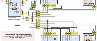
Complete electrical diagram of the VAZ 2114 with decoding
The complete package of electrical equipment of the VAZ 2114 can be divided into two types. The fundamental differences are due to changes in equipment depending on the year of manufacture and equipment of the car. In this case, the entire drawing can be divided into several zones.
- The engine compartment is responsible for providing voltage to sensors and instruments located directly inside the engine compartment.
- Salon compartment. The part is primarily used to connect the front and rear compartments.
- Instrument panel assembly. The pinout is displayed directly on the controls and dashboard. All elements of the on-board network are combined here and connected to buttons or indicators.
- Stern joint. The small module combines chain elements located at the rear of the machine. Typically, the segment is subject to frequent damage, which is due to the constant transportation of goods in the luggage compartment. When moving over obstacles, loads can damage sensitive equipment.
You can also separate small units – these are door units, windshield wipers and others. For ease of perception, each beam is considered separately.
VAZ 2114 instrument panel pinout
The terminals of all vehicle equipment are concentrated here. Due to the fact that the unit is located under the dashboard and is subject to constant condensation or fogging, some users treat it with hot melt adhesive. Even a thin coating can reliably protect the device from water ingress.
Elements are connected to devices or controls:
- 1 – switch key for heated rear glass;
- 2/6 – fog light switches, for rear/front module;
- 3 – plastic block for activating head optics and turn signals;
- 4 – fuse block;
- 5 – wiper mode switch;
- 7 – on-board system indication;
- 8 – supply voltage to the additional harness;
- 9 – dashboard;
- 10 – “male” for powering the on-board computer;
- 11 – terminal to the ignition device;
- 12 – for door wiring;
- 13/14 – fuses;
- 16 – ignition break;
- 17 – stove motor;
- 18 – secondary resistance of the stove;
- 19 – current supply to the ignition unloading relay;
- 20 – protective relay for rear fog lights;
- 21 – starter fuse relay;
- 22 – remote socket for a portable lamp;
- 23 – power supply for the cigarette lighter;
- 24 – for illumination of the glove compartment;
- 25-27 – illuminators;
- 28 – stove switch;
- 29 – tidy lighting with rheostat;
- 30 – stop switch;
- 31/32 – horn/hazard warning switch, respectively;
- 33 – backlight of the stove panel;
- 34 – fuse;
- 35 – protective relay for seat heating elements;
- Ш1/4 – mounting block jumpers;
- X1/2 – dashboard controls;
- A – protective ground output (usually black).
General concepts
In order for the glass to be heated evenly and to a strictly defined temperature (sufficient to evaporate moisture, but not exceeding safe limits), a special electrically conductive thread (thin flat wire) is used, which has a certain, strictly standardized resistance.
Sometimes in winter, a car enthusiast may think that the heating has failed because the glass does not defrost for a long time. In such a situation, there is a high probability that the heating is working properly, but its temperature is not enough to melt a significant layer of ice. You should remove the ice manually using a special scraper, and then turn on the heating again.
Electrical equipment of the front of the car
The following is a breakdown of the front cable bundle, excluding fog lights:
- 1 – output terminals of the starter contact group;
- 2 – battery, connection of power cables;
- 3 – standard “father” of the generator;
- 4 – blocks for connecting the power conductors of the battery and generator to the front assembly of electrical equipment;
- 5 – part of the fuse mounting block;
- 6 – standard horn;
- 7 – sensor that measures the temperature of antifreeze in the power plant;
- 8 – standard sensor for measuring the washer fluid residue in the tank; when activated, the corresponding indicator on the device lights up;
- 9/10 – left and right headlights, respectively;
- 11 – external thermometer;
- 12 – standard reverse gear lamp switch;
- 13 – drive of the electric fan of the generator;
- 14 – connector to the ignition system module;
- 15 – in the VAZ 2114 scheme the injector is not used, it is used only for the carburetor;
- 16 – electronic brake fluid level sensor; in case of a critical drop, an exclamation mark lights up on the instrument panel;
- 17 – built-in oil level sensor in the crankcase compartment of the power plant; when activated, the red light on the instrument panel lights up;
- 18 – similar for the engine cooling system;
- Ш5-8 – mounting block connectors;
- A1/2, B1/2 – grounding terminals.
Diagram of the heater and heated rear window
- Mounting block;
- Ignition switch;
- Ignition relay;
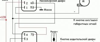
- Heater motor switch;
- Additional resistor;
- Heater motor;
- Rear window heating switch with turn-on indicator lamp;
- Rear window heating element;
- K7 - Relay for turning on the heated rear window.
Methods for repairing heating element filaments
There are several ways to restore the functionality of a heating wire at home.
Using conductive pastes and adhesives
The simplest and most effective is with the help of special repair kits, for example DONE DEAL DD6590, designed for repairing threads and contacts of the rear window heating for both amateurs and professionals. The good thing about this method is that it does not require tools or materials. It is enough to apply a little conductive paste according to the attached instructions to the place where the syringe thread is broken, wait for the paste to harden and complete the repair. But this set costs more than $15.
The second method is similar to the previous one. But instead of a proprietary set, purchased conductive adhesives are used, for example. Glue is applied to the place where the thread breaks, covering the entire part of the thread by one centimeter on each side. To obtain a neat look, use a stencil made of electrical tape or adhesive tape. For reliability, glue is applied twice. It is recommended to lay a piece of tinned copper wire with a diameter of 0.3-0.5 mm between the layers of conductive glue.
It is believed that conductive paste or glue for repairing glass heater wires can be made independently by mixing paint or glue with brass filings in a one-to-one ratio. The resulting composition is applied through a stencil in a thin layer until the thread breaks in several layers. But the reliability of this technology has not been confirmed by practice.
Electroplated copper deposition
Another method is copper electroplating. The method for repairing the heater filament looks interesting. But from personal experience I can say that the reliability of such coatings at home is low. Therefore, I hesitated to use this technology.
Using soft soldering
The mechanical method of restoring the integrity of the rear window heater filaments using soft soldering has become widespread. I tested the reliability of this method when repairing the rear window heating threads in my car. The step-by-step instructions below, based on my experience, will allow you to easily repair your heater wire yourself in minutes with virtually no cost.
On the advice of Internet theorists, I made a big mistake and tried to clean the thread with sandpaper. As a result, instead of breaking a thread 1 mm wide, a break of more than 1 cm occurred. The thread ribbon is very thin, only a couple of tens of microns, and can be erased even with the finest grit sandpaper instantly. However, the heater wires are not covered with anything, and it is enough to degrease the welding area with a rag moistened with alcohol or acetone.
If the width of the wire break is less than 1 mm, you can do without soldering an additional conductor. In my case, the gap width was large, and I had to prepare a piece of copper wire for the jumper in advance. A current of about 1 A flows through the heater conductor, based on this we select a wire with a cross-section of 0.17 mm 2, which corresponds to a diameter of 0.45 mm, according to the table of wire sections. The length of the copper jumper should be equal to the width of the wire break plus 2 cm. Before soldering, the jumper must be tinned with a thick layer of POS-61 tin-lead solder. There is no need to tin the heater wire.
To ensure that the solder adheres securely to the heater wire, before soldering the jumper, coat the wire in the soldering area with a brush with a thin layer of zinc chloride flux.
After this, the jumper is pressed against the heating wire and heated for a second with a 12 W soldering iron. The hand is moved to the side. The jumper should be kept on a string. Trying to pull it out to check the quality of the solder is unacceptable; it will fall off and tear off a piece of the heater wire. Unfortunately, this has not been tested empirically. As a result of the experiments, we had to solder a jumper 5 cm long.
After soldering one end of the jumper, the other is pressed tightly against the wire and is also heated with a soldering iron. At the end of welding, the glass is thoroughly washed with water to remove residual acid flux.
Finally, for reliability, even if this is not necessary, I covered the jumper welded on top with transparent superglue “Moment” based on cyanoacrylates, the heat resistance of which is about 70 ° C. The heater does not heat up to the above temperature.
As a result, the time to repair a broken thread with your own hands, taking into account all the preparatory work, was no more than ten minutes. The repaired threads have been in use for more than three years.
Reworking the low beam button
It, like an abrasive, increases the friction force, which creates resistance to glass movement.
Installing PTF provides better illumination of the roadside and side markings, reducing the risk of leaving the road. Some motorists are of the erroneous opinion that fog lights with high lighting efficiency can only be yellow. These grooves tend to become clogged with dirt.
This allowed additional parts to be kept to a minimum and simplified the design.
A well-known situation arises - the blinding of drivers of oncoming vehicles, which increases the risk of an accident. This is due to the geometry of the lifting mechanism. Is this really true?
We recommend: Era switch how to connect
Manual window lifters
There are 8 clips installed around the entire perimeter of the door. Replacement cost Replacing VAZ window regulators is cheaper than installing electric mechanisms to replace manual ones.
They create fewer electrical problems, but the inconvenience of using them is that while in the driver's seat, it is impossible to open the window on the passenger side without being distracted from driving. The front left window regulator fails faster due to more frequent use.
Registration
Location of relays and fuses of the old model 1 - relay for turning on the headlight cleaner K6; 2 — rear window washer time relay K1; 3 - relay breaker for direction indicators and hazard warning lights K2; 4 — windshield wiper relay K3; 5 — contact jumpers in place of the relay for monitoring the health of the lamps; 6 — relay for turning on the heated rear window K10; 7 - spare fuse; 8 — relay for turning on the main beam headlights K5; 9 — relay for turning on the low beam headlights K11; 10 - fuse; 11 — relay for switching on the electric motor of the engine cooling system fan K9; 12 - relay for turning on the sound signal K8. In the cabin, in a place convenient for the driver, a button for turning on the PTF is installed. The grille with the speaker is removed from the standard front panel. To illuminate the central locking button 4. On the driver's door there is a block of buttons that control all windows that have an electrical connection for VAZ power windows
It consists of a roller and a gearbox, which is rotated either by a handle or by an electric motor if there is an electrical circuit for the VAZ window regulator. Fill the upper part of the resulting pads with silicone. The mentioned wires are pulled to the fuse block from the fog light relay. I have not yet figured out how to overcome this problem, so I have disabled the microswitch for now and use the central lock button. Absent 8. VAZ 2110,11,12 CONNECTION OF FRONT FOG LIGHTS ACCORDING TO STANDARD
The dashboard diagram (Fig. 1.1) includes controls:
1 – lever-switch for headlight or turn signal modes.
2 – nozzle for blowing the front door glass.
3 – instrument cluster.
4 – steering wheel.
5 – button to turn off sound signals.
6 – button to turn off the alarm. Pressing the button causes the warning light and direction indicators to flash.
Photo 1. Hazard switch off button
7 – ignition switch combined with an anti-theft device. Never turn off the ignition or remove the key from the lock while driving, otherwise the steering will be blocked and the vehicle will lose control. The ignition key can have three positions:
- 0 – “disabled”. Consumers are disconnected, the key can be easily removed. When the key is removed, the closing mechanism of the anti-theft system is activated. To guarantee the steering shaft block, turn the steering wheel left or right until it clicks. To turn off the anti-theft device, you need to insert the key into the ignition and, turning the steering wheel left and right, turn the key to position “I”;
- I – “ignition”. The ignition is on, the key is not removed, the steering is unlocked;
- II – “starter”. The key cannot be removed, the steering is unlocked. The position is achieved by turning the key to overcome the elastic force of the spring. The key is not locked in this position; it must be held by hand for the starter to operate. The ignition switch is also equipped with a starter activation unit while the engine is running.
To repeat turning on the starter after a failed start attempt, you need to move the ignition key from position “I” to position “0”, and then again to position “II”.
8 – switch lever for windshield washer and windshield wipers.
9 – immobilizer sensor, transmits a special code from the code key through the immobilizer to the engine control unit.
10 – set of signal lights for the on-board control system. The complex contains (Fig. 1.2): 1 – oil level drop signal; 2 – low level signal in the windshield washer tank; 3 – low coolant level signal; 4 – door open signal; 5 – signal of malfunction of the brake light and side lights; 6 – signal of wear of the linings on the brake pads; 7 – the signal indicates that the seat belts are not fastened.
11 – external lighting switch.
12 – block of keys for turning off fog lights, fog lights, heated rear window.
13 – trip computer, installed on some vehicles, designed to display one of the parameters: current fuel consumption (or average total fuel consumption), average speed, distance traveled, current time, time on the road.
15 – control lamp for anti-lock braking system (ABS). Installed in place of the plug, if equipped with an anti-lock braking system.
16 – airbag control lamp. If the pillow itself is present, it is installed in place of the plug.
17 – central nozzles of the ventilation and heating systems of the cabin.
18 – cover of the glove box (upper). To use the upper glove compartment while the lower glove compartment lid is open, press the upper lid lock lever. The lock lever is located in the niche of the lower glove compartment on top.
19 – side nozzle of the ventilation and heating systems of the cabin.
20 – glove box cover (lower). To open it, you need to press the lock handle to the handle. If the external lighting is turned on, a special illumination of the inside of the box will automatically work.
21 – magazine shelf.
22 – control panel for interior ventilation and heating systems.
23 – socket for audio equipment. It is planned to install audio equipment that meets international standards in size and mounting principle.
Watch a video of testing the dashboard of a VAZ-2115 passenger car here:
Fuses and relays VAZ 2114 2115 2113
VAZ 2113, 2114, 2115 cars considered
Attention! The location of fuses and relays in the blocks may differ depending on the year of manufacture and vehicle equipment. You can see earlier modifications of fuse blocks on this page.
Fuses for the VAZ 2114 injector and VAZ 2115 injector are also described on this page.
Where are the fuses and relays located?
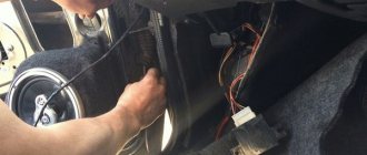
The main part of the fuses and relays is located in the mounting block of the engine compartment.
To get to the block you need to press two latches and remove the cover
Using pliers installed in the block, remove the fuses
Lada 2114 2012, engine Gasoline 1.5 liter., 1 hp, Front drive, Manual — vehicle breakdown
Comments 11
I'll write here, maybe someone will help. New glass was installed. The heating works. But after 10-15 minutes the fuse that goes to the cigarette lighter (radio) blows out at 20.
The contacts are not sealed on the glass, have you checked?
I checked and they seem normal. You will need to remove and clean the contacts.
Same bullshit, today I'll go see an electrician
Post back later if it works.
poked with a tester, they said the glass needs to be replaced (((((
Badly. Thanks for the answer
poked with a tester, they said the glass needs to be replaced (((((
Looks like I also have glass in need of replacement.(((
I heard that there is some kind of special paste that you rub with it and the conductivity of the heating element is restored. I don't know how true this is. Well, the glass will have to be changed...
This paste is a conductive adhesive, available in radio stores... it is applied to the damaged areas of the glass heating element (visually it looks like a 1-2 mm break on the track itself. The restoration work looks like this: 1. Shine a flashlight through the glass along each track separately, along the entire length, we find the damaged areas. 2. LIGHTLY use a blade to make a couple of scratches on the path along the edges of the cliff and make a thin path of paste, thereby restoring the conductivity. 3. Wait for complete crystallization of the paste (from a couple of hours to a day, as in the instructions). 4. PROFIT!
If this paste is difficult to access in your region, you can make it yourself. Here are a couple of options:
Paint and shavings. The shavings are “mined” from a copper-brass bar with a file. The paint is preferably red, matching the color of the threads. Mix the shavings with paint (50/50) to a dough-like state. We make a stencil from electrical tape (adhesive tape). Turn on the heating and apply the mixture using a stencil. You will hear that “there is contact” by the reaction at the repair site. It should be a slight hiss. All. You can go right away.
Glue and shavings. A similar way to obtain a conductive mass is to use glue, for example BF-2, instead of paint. In both cases. If the area where the conductive thread is broken is large enough, then for reliability you can use a thin wire (core).
In this guide, we will tell you where the rear window heating fuse of the VAZ 2114 is located. We will also list what other electrical systems are connected to this circuit.
VAZ-2114 wiring harness diagrams
Instrument panel harness
Glove compartment lighting harness
Front harness (without fog lights)
Rear harness VAZ-2114
Wiper Harness
Additional harness
Connects to the instrument panel, the connector is next to the hood handle. Pink - door lock, permanent plus, fuse hangs next to the hood release handle. White and black - on the door for electric windows, plus during ignition, switched on through a relay and fuse in the mounting block. Also in the photo is the wiring for the radio speakers.
Right door harness
Connects to an additional harness.
Left door harness
Connects to an additional harness.
Seat heating harness
The gray wire is connected to the connector where the additional harness is connected (to the gray wire if there is one), plus when igniting, the relay is attached next to the mounting block and the fuse is located next to the hood handle. The white wire is connected to the additional harness, button illumination.
General concepts
In order for the glass to be heated evenly and to a strictly defined temperature (sufficient to evaporate moisture, but not exceeding safe limits), a special electrically conductive thread (thin flat wire) is used, which has a certain, strictly standardized resistance.
When current passes through it, it heats up - just like the coils in electric stoves and kettles heat up, only at a much lower temperature. Thanks to this heating, as well as the fact that it occurs evenly over the entire plane of the glass (after all, the thread is applied on it at equal distances), the latter dries out quite quickly and is cleared of moisture.
Sometimes in winter, a car enthusiast may think that the heating has failed because the glass does not defrost for a long time. In such a situation, there is a high probability that the heating is working properly, but its temperature is not enough to melt a significant layer of ice. You should remove the ice manually using a special scraper, and then turn on the heating again.