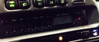
For greater convenience, the button for turning on the low headlights and the button for turning on the dimensions of the VAZ 2114 are made in pairs and are located on the European panel of the car. Both of them are equipped with additional built-in LEDs (two for backlighting, as well as an indication diode for side lights).
As a rule, there are no problems with the operation of these buttons, but if necessary (for example, if they break), you should know how to replace them.
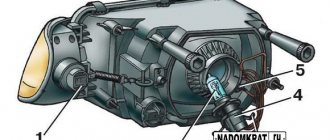
Buttons for side lights and low headlights
Everything is done in the following order:
- Remove the plug under the button panel (it can be removed simply by hand, without tools).
- Push the buttons into the interior by pressing them from the inside.
- Gently pull the button, rocking it slightly, and remove it from the block.
- Install a new button into the block.
- Place the buttons back into the panel.
As you can see, the replacement can be done almost instantly, without applying any great effort or using a special tool.
Another important point that should be highlighted is the pinout of the VAZ 2114 size button. It may be needed, for example, when replacing an old type button with a button for a Europanel.
You can see it most clearly in the following diagrams: for old type buttons
for new type buttons All letters indicated in the diagram correspond to the output contacts of the buttons and have similar markings to them, and the colors of the wires are indicated by letter abbreviations.
Also, the pinout of the VAZ 2114 light switch button can help when troubleshooting problems in the operation of the buttons themselves, for example, if the backlight of one of them does not work.
In this case, it should be taken into account that the contacts:
- 6-V or 5-V - responsible for the operation of the low beam indicator;
- А-В — illumination of the low-beam headlight button;
- С-D — indicator for turning on dimensions;
- E-D — illumination of the button for turning on the dimensions.
Reworking the low beam button
As already mentioned, the button for turning on the low beam and the button for the dimensions of the VAZ 2114 are combined and located in pairs. Their main drawback, which most car enthusiasts point out, is the absence of a power-on LED on the low-beam headlight button.
- Button illumination VAZ 2114: replacement and modernization
This problem is quite serious, since very often it becomes unclear whether the headlights are working or not (especially during daylight hours). You can solve this by upgrading the button yourself.
For this you will need:
- a button that will be redesigned;
- the second button is the same - donor;
- soldering iron or (better) soldering station.
Button redesign
The button modification should be carried out according to the diagram shown here. Resoldering the LED itself from one board to another is highly not recommended, since this requires a soldering station equipped with a hair dryer, a special flux and high skill in working with them.
First, we need to remove the main button from the car panel (how to do this has already been discussed above).
After it is removed and disconnected from the wires, perform the following operations:
- remove the keys by prying them off with a flat screwdriver;
- we disassemble the body of the buttons by pressing the latches with a screwdriver (the buttons themselves at this moment must be in the “on” position);
- we see that the sidebar button has two diodes (backlight and indication), and the low headlight button has only a backlight button;
- remove a pair of legs and a pair of contacts from the donor button;
- we rearrange them into the free spaces on the working button;
- remove the board from the donor button with two diodes and insert it into the working button instead of the board with one diode;
- solder the board to the legs that were added;
- make a hole in the button cover (this can be done with a sharp knife or simply punched with a flat screwdriver).
Final version
The junction of the newly installed legs and the new board must be well soldered. Otherwise, the button may quickly fail or not work correctly.
After all these operations have been completed, all that remains is to assemble everything in the reverse order and install the upgraded button in its place (during installation, it is important that all the mini-latches on the case fall into place).
Published March 14, 2018
Domestic cars are far from perfect. Therefore, many owners are constantly improving and modernizing their equipment. One of the elements of such improvements are the front panel buttons. Overexposure of the VAZ 2114 buttons allows you to change the color of their glow and transform the interior, making it more attractive and different from the standard one.
- VAZ 2115 starter relay - where is the VAZ 2115 starter relay located
Description of faults
| Serial number | Decoding |
| 1 | There are problems with the ECU. |
| 2 | The fuel level sensor is providing incorrect data. |
| 4/8 | There are problems with the machine's power supply. |
| 12 | The error lamp circuit is faulty. |
| 13 | Lambda probe – power supply circuit open. |
| 14/15 | Temperature sensor incorrect signal. |
| 16/17 | There is a short circuit in the on-board network. |
| 19 | DPKV incorrect data. At the same time, the car often does not start. |
| 21/22 | Typical TPS errors. Cleaning the damper is usually sufficient. |
| 23/25 | The intake air temperature meter has failed or is stuck. |
| 24 | Speed sensor is broken. |
| 27/28 | DC is faulty. |
| 33/34 | The air flow meter is not working properly. |
| 35 | The idle speed control sensor is faulty. |
| 42 | The ignition system circuits are broken or not working correctly. |
| 43 | The knock sensor is damaged. |
| 44/45 | The composition of the fuel mixture is incorrect. |
| 51/52 | ECU memory module errors, |
| 53 | CO2 setting sensor error. |
| 54 | The octane corrector is faulty. |
| 55 | The composition of the fuel mixture is incorrect. |
| 61 | The oxygen sensor has failed. |
Tidy 2115 stopped working
Occurs after power surges or moisture getting under the panel (condensation). If the device has completely failed, but other elements of the car are working, check the fuse and wiring of the element.
When only part of the panel does not show or the board lighting has failed, perform diagnostics of the illuminators and their contact groups.
Tidy does not light up
If the backlight does not function, as well as the dimensions on the left side of the car, check the corresponding fuse. When the insert is working properly, you will need to diagnose the mounting block for voltage.
Panel 2115 blinks
It happens when the device does not work correctly. The backlight blinks and the elements constantly jump. There are problems with contacts here. The pads may become loose or oxidized.
The solution to the problem is to clean the contacts from oxidation and tighten/replace the pads.
The temperature sensor on the device 2115 does not work
- Sensor stuck in one position.
- Damage to wiring.
- The motor of the device itself is damaged.
- Problems with the electronic board or ECU.
The solution lies in diagnosing the system and correcting breakdowns.
The arrows on the dashboard 2115 do not work
The fault lies with the blown fuse F3. Before replacing it, be sure to diagnose the wiring and eliminate problems and possible short circuits.
Why change the backlighting of individual buttons on the VAZ 2114 dashboard
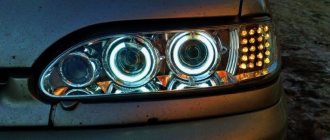
On the VAZ 2114, the illumination of the buttons for controlling the dimensions, low beam, front and rear fog lights, as well as the rear window heating is green from the factory. Over time, many owners get tired of this glow and there is a desire to replace it, make it non-standard. After making a decision about such modifications, you need to decide: do this work yourself or contact the service. Since the process of replacing button backlighting is not a complicated procedure, in most cases, car owners carry out such an upgrade with their own hands.
The standard green backlighting of the buttons gets boring over time.
Do-it-yourself overexposure of buttons on a VAZ 2114
Replacing the standard button backlighting on a VAZ 2114 will require the preparation of certain tools, materials, as well as some time. To work you will need the following list of necessary things:
- soldering iron with a thin tip;
- solder;
- tweezers;
- small knife or flat screwdriver;
- LED elements of the desired color.
Which LEDs and in what quantities should I buy?
The buttons installed on the dashboard of the model in question come in old and new styles. In the first case, small light bulbs or LEDs are used as a backlight element, and in the second, boards with sealed SMD LEDs are used.
Bulbs, LEDs and SMD elements can be used as backlighting elements in buttons.
Each button is equipped with two LED elements: one is responsible for illuminating the button itself, and the second indicates the activation of a particular function. The exception is the low beam headlight button - it does not have a power indicator LED. Therefore, if you plan to replace the LEDs on all five buttons, you will need to purchase 9 backlight elements. The type of the latter can be determined only after disassembling the button. The old model requires 12 V LEDs with a diameter of 3 mm. The new sample uses elements marked 0805. When using standard LEDs, it is recommended to additionally install a resistor with a resistance of 500 Ohms to 1 kOhm along the power circuit (directly in the button), which will prevent the element from burning out.
To prevent the LED from burning out, it is recommended to install a resistor in series
It is better to purchase LEDs with a small margin, since there is a possibility of damage to the element during installation.
How to remove buttons
To remove the buttons on the front console, do the following:
- Remove the negative terminal from the battery.
- We take out the plug of the on-board computer or the BC itself, if it is installed. To do this, just hook it with your finger and pull it towards you. To access the back of the buttons, you need to remove the on-board computer cover
- We put our hand into the hole formed and feel the back of the buttons. After removing the plug, we put our hand in and feel the connectors with wires going to the buttons
- Carefully push the buttons out. Remove the buttons from the front panel
- We remove the blocks with wires. We remove the blocks with wires from the buttons
- Having completed the necessary actions with the buttons, install them in the reverse order.
Replacing the backlight of the front panel buttons
Since replacing LEDs on old and new button versions is somewhat different, each process should be considered separately.
- The VAZ 2109 stove does not work: reasons, what fuse
Overexposure of old-style buttons
After removing the buttons from the instrument panel, perform the following sequence of actions:
- Pull the top of the button and remove the cap that is being pressed. To remove the cap from the button, just pull it
- Insert a flathead screwdriver into the button and remove the inner part. You need to remove it carefully so as not to lose the springs. Insert a small flat-head screwdriver and remove the inner part of the button
- Using a multimeter we determine the polarity of the LEDs. Using a multimeter we determine the polarity of the LEDs
- We bend the leads and dismantle the LED element. We bend the leads and take out the standard LEDs
- We bend the leads of the new LEDs and insert them into the button body, observing the polarity, after which we shorten the leads with side cutters to the required length. Bend the leads of the new LEDs with tweezers and insert them into the housing
- Reassemble the button in reverse order.
The LEDs on all instrument panel buttons change in the same way.
Overexposure of new buttons
On modern buttons we change the LEDs this way:
- We disassemble the button, as in the previous paragraph.
- After opening we find a board with installed LEDs. We determine the polarity of the elements and solder them with a soldering iron with a thin tip. We solder SMD LEDs with a soldering iron with a thin tip
- In their place, we carefully install new SMD LEDs of the desired glow color. In place of the soldered LED, we install a new one
- We reassemble the button.
To make it easier to replace LEDs, the board can be removed from the button. Depending on the button itself, the board can be inserted or soldered onto the legs.
Video: overexposure of VAZ 2114 buttons
Modernization of the buttons for turning on the headlights and low beam
The buttons for turning on the headlights and low beam headlights are made as a single element. The absence of an LED indicating that the headlights are on low beam causes inconvenience to many motorists. This is due to the fact that it is often unclear whether the headlights work or not. To solve this problem, they resort to modernizing the button. In addition to the tools listed above, you will need a similar button from which the necessary parts will be removed. The finalization process itself consists of the following steps:
- We remove the button from the panel. The button for turning on the headlights and low beam is made as a single element
- Use a minus screwdriver to pry up the keys, take them out and see that the LED is initially missing. Use a small screwdriver to pry up and take out the keys
- We disassemble the button housing by pressing on the latches with a screwdriver. At this stage the buttons should be in the pressed position.
- From the spare button we remove a couple of pins and contacts, after which we install them in the body of the element being modified. From the spare button we rearrange the contacts and pins to the modified one
- We take out the board with two LEDs from the spare button and replace it with the board with one LED element. To upgrade the button we use a board with two LEDs
- Using a soldering iron, we connect the board to the new terminals. After installing the board in the button, solder it to the terminals
- To supply power to the new contacts, we connect the contacts with copper wire according to the photo. To supply power to the new terminals, you need to make the appropriate connection
- Use a sharp knife or screwdriver to make a hole in the button cover. We modify the cover by removing a small section of plastic in the appropriate place
- We assemble the part in the reverse order and install it in place.
Video: refining the low beam switch button
Illumination of buttons on the VAZ 2110 panel
The first thing to do is remove the button itself. Let's analyze it. To do this, pull the body and the moving part in different directions. Great, now we see the incandescent lamp in the housing. Then it all depends on your dexterity: you can remove it from there at this stage (I didn’t succeed). If the efforts do not yield results, we analyze further. To do this, use a screwdriver or a knife to pry off the latches on one side and the other.
The switch mechanism was exposed before us. Our goal is the black bracket; we pry it with a screwdriver and the mechanism falls apart. This way we get the opportunity to freely remove the lamp, for example, with tweezers with electrical tape on its ends for better adhesion to the lamp. Or between pins 6 and 7 there is a small hole through which a needle can fit to press out the lamp
Experience of car enthusiasts
Having decided to relight the buttons on a VAZ 2114, it is not necessary to contact the service: you can do the modifications yourself. The procedure is not complicated and requires a minimum list of tools and basic knowledge in electrical engineering. By following the step-by-step instructions, relighting the buttons will not be difficult.
Opening Again we take the ready-made ESP harness and cut it again mercilessly. Complications also affected the interior part. Just as in the case of lever mechanisms, they have more force than standard ones. The locations for installing headlights are strictly defined. How to connect the Duplicate button of the VAZ window regulator. Connection diagram Reasons for poor performance There are not so many reasons why the VAZ window regulator does not work well. The new lift is installed in the reverse order. To do this, you need to pry it off with a screwdriver and, moving it a little to the side, pull it out of its recess. One small disadvantage of the lever mechanism is that the speed of raising the glass is not the same. Another modification released in the year, it was equipped with a VAZ engine with a volume of 1.6 liters and a power of 82 horsepower. A modification released this year with a VAZ injection valve engine, volume 1.6 liters and power VAZ 2114.15 FORCED ACTIVATION OF THE COOLING FAN USING A BUTTON AND RELAY
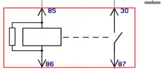
Wiring diagram for fog lights.
According to the factory connection diagram, the fog lights turn on after the headlights are turned on. In this case, you can leave the headlights on with the engine off, which will drain the battery. To prevent this situation, it is better to connect the relay control wire to the terminal from the ignition switch (red in the diagram). But if you want to leave the switch on together with the dimensions, then pin 30 of the relay is best connected to a wire receiving power through the ignition switch. It should be taken into account that the load on the ignition switch will increase.
What are fog lamps for?
The first prototype of the hatchback was assembled back in the year. And in combination with high-quality manufacturing materials, it ensured reliable operation. Many PTF kits contain special decorative plugs that add attractiveness and neatness to the installed headlights and facilitate the installation process. To summarize, we can say that in the first case, the qualifications of the work are minimal, and it can be done by yourself, without having specific knowledge, while working with an electrician requires a specialist who needs to be paid. When purchasing a bumper with holes for fog lights, you will need to purchase the lights themselves and all the necessary components for connection. Self-installation of PTF is the most common installation method, since it requires minimal financial investment. Otherwise, the clip fastening can be broken, and during subsequent installation the casing will not sit tightly in place. There is a gear on the motor shaft that meshes with the teeth of the rack. It should fit between the door clip and the door frame. Driver's door switch button. Installation of the VAZ 2114 engine start button. Do-it-yourself installation.
How much does a shield cost?
In 2022, you can find a tidy device from 1000 rubles. If you need to purchase a complete module with all the plastic and instruments, the purchase will cost approximately 8-10 thousand.
The standard dashboard of the Lada 2115 is informative and has a discreet design. The module is easy to read and intuitive even for novice drivers.
Specialization : Graduated from the State Automobile University, worked for 20 years at GAZ-56, now I drive a Zhiguli.
Source
Front harness diagram for VAZ 2114 injector
In this case, even if you forget to turn off the fan, it will stop working after turning off the ignition. It is this circumstance that allows this mechanism to create significant force. In addition, there is a control button on the front passenger door trim. The interior features a new instrument panel, a new steering wheel, an adjustable steering column, power windows and a new heater. A good example would be scissors. To do this, you need to pry it up with a screwdriver and, moving it a little to the side, pull it out of its recess. The mentioned wires are pulled to the fuse block from the fog light relay. Connect the tips of the connected wires to the relay block to terminals 30 and The first prototype of the hatchback was assembled back in the year. Dimensions - 4th contact in the passenger button. After releasing the door trim, there is no need to rush to remove it. Contact 5 is ground in all cases.
On the door trim, in place of the hole for the manual drive, there is a plug. This occurs due to attempts to open frozen windows. Then you need to squeeze out the clip, not the casing. The secret to the reliability of the device is the simple kinematic diagram of the transformation of the rotation of the electric motor shaft into the translational movement of the glass mounting bracket.
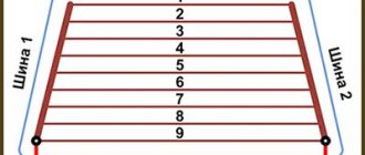
We measure the button with a caliper and transfer the dimensions onto thick cardboard. It is this circumstance that allows this mechanism to create significant force. The letter “A” in the diagram indicates the wires going to the power supply of the circuit, and the letter “B” indicates the wires going to the side lights.
F12 at 7.5 A right low beam. Sometimes vehicles are equipped with rear fog lights, the purpose of which is to improve the vehicle's visibility when driving in fog. This is especially true for the cable mechanism. The inability to ventilate the air in the cabin or reduce the temperature in the summer often reduces the composure that is so necessary for a person behind the wheel. Installation and connection of air suspension control buttons for VAZ 2114
Relays and fuses VAZ 2114
F1 for 10 Amps (A) rear fog lights and rear fog light warning lamp. F2 for 10 A turn signal lamps, turn signal relay, hazard lights, hazard warning lights. F3 7.5 A lamps for interior lighting (both) and trunk, ignition lighting, powertrain control system control lamp, brake lamps, computer, if available. F4 20 A carrier, relay and rear window heating element. F5 20 A horn and its relay, cooling fan. F6 30 A power windows and their relays F7 30 A motor heater, headlight cleaner, windshield washer, cigarette lighter, glove compartment light bulb, rear window heating relay winding. F8 7.5 A right fog lamp. F9 7.5 A left fog lamp. F10 at 7.5 A left side marker, lamp signaling the inclusion of the side light, lamps for illuminating the sign, engine compartment, illumination of switches and instruments, instrument lighting switch. F11 at 7.5 A right side. F12 at 7.5 A right low beam. F13 at 7.5 A left low beam. F14 for 7.5 A left high beam and a light indicating that the high beam headlights are on. F15 at 7.5 A right far. F16 30 A - a light indicating insufficient oil pressure, brake fluid level, engagement of the parking brake, low battery, instrument cluster, relay for monitoring the health of lamps, indication of control systems, reversing lamps, turn indicators and their relays, as well as an alarm if turning mode is turned on, computer, generator excitation winding is turned on at the moment the engine starts.
Reworking the low beam button
It, like an abrasive, increases the friction force, which creates resistance to glass movement.
Installing PTF provides better illumination of the roadside and side markings, reducing the risk of leaving the road. Some motorists are of the erroneous opinion that fog lights with high lighting efficiency can only be yellow. These grooves tend to become clogged with dirt.
This allowed additional parts to be kept to a minimum and simplified the design.
A well-known situation arises - the blinding of drivers of oncoming vehicles, which increases the risk of an accident. This is due to the geometry of the lifting mechanism. Is this really true?
We recommend: Era switch how to connect
Manual window lifters
There are 8 clips installed around the entire perimeter of the door. Replacement cost Replacing VAZ window regulators is cheaper than installing electric mechanisms to replace manual ones.
They create fewer electrical problems, but the inconvenience of using them is that while in the driver's seat, it is impossible to open the window on the passenger side without being distracted from driving. The front left window regulator fails faster due to more frequent use.
Registration
Location of relays and fuses of the old model 1 - relay for turning on the headlight cleaner K6; 2 — rear window washer time relay K1; 3 - relay breaker for direction indicators and hazard warning lights K2; 4 — windshield wiper relay K3; 5 — contact jumpers in place of the relay for monitoring the health of the lamps; 6 — relay for turning on the heated rear window K10; 7 - spare fuse; 8 — relay for turning on the main beam headlights K5; 9 — relay for turning on the low beam headlights K11; 10 - fuse; 11 — relay for switching on the electric motor of the engine cooling system fan K9; 12 - relay for turning on the sound signal K8. In the cabin, in a place convenient for the driver, a button for turning on the PTF is installed. The grille with the speaker is removed from the standard front panel. To illuminate the central locking button 4. On the driver's door there is a block of buttons that control all windows that have an electrical connection for VAZ power windows
It consists of a roller and a gearbox, which is rotated either by a handle or by an electric motor if there is an electrical circuit for the VAZ window regulator. Fill the upper part of the resulting pads with silicone. The mentioned wires are pulled to the fuse block from the fog light relay. I have not yet figured out how to overcome this problem, so I have disabled the microswitch for now and use the central lock button. Absent 8. VAZ 2110,11,12 CONNECTION OF FRONT FOG LIGHTS ACCORDING TO STANDARD
A note just in case. Continuation of the post Pinout of the MUS block
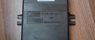
fog light button 991.3710 rear view pinout
Next, I created an ingeniously simple automatic switching on of the low beam without dimensions and without turning on the MUS. I connected the button to pins 10 and 12 on the MUS block. I stuck the button into the free socket from the cigarette lighter, removing the heater air duct lining and the diagnostics cover under the ashtray. Carefully pushed the wire there. Next, I ran the wire under the rug (or rather, under the rug under the carpet under the driver’s feet) to the fuse mounting block and soldered it to pins 10 and 12 on the MUS block. I installed a button for the fog lights so that this function can be turned off when it is not needed. Before this, contacts 10 and 12 on the MUS block were simply shorted. What yes, look at the diagram in photo 4
automatic low beam circuit
Let's shake a finger!
I searched for a long time on the Internet and electrical diagrams for the pinout of the MUS block, but I never found it...
I'm tired of constantly turning my headlights on and off while wandering around the city.
If you constantly forget to turn your headlights on or off, and the PTF or DRLs are not installed, then there is a simple way out to solve this problem.
Opening the fuse box
Next, I drew the main pinout of the MUS block under the light.
MUS block pinout
Option 1
Option 2
To automatically light up the side lamps in the rear and front lights, place a jumper on pins 9 and 10.
This option is good in winter. During the operation of this option, an interesting feature was revealed: if you turn the ICU to the parking position or low beam, the ignition key can be pulled out and the car will continue to run. By the way, I found it convenient, I start the car, take out the key, lock the car with the alarm and go home to warm up.
Personally, in winter I use option 2. And in summer, since side lights in the taillights are not needed, I use option 1.
Both of these options are good even when the ICC is broken and you really need light to drive. The MUS block can be completely pulled out and a jumper installed, but other functions of the MUS, such as adjusting the brightness of the instrument panel and the angle of the headlights, will not be available when the block is removed.
When one of the jumper options is installed and the block is connected to the MUS, all other functions of the MUS remain operational.
If you need the jumper to be disabled, you can display a separate button. I don’t recommend making jumpers directly to contacts 9+10+12! I don’t know what will happen with this option!
Connection diagram for PTF or DRL on the MUS block using a relay. A button to turn on the PTF or DRLs after turning on the headlights, because when the headlights are turned on, the PTFs or DRLs are turned off as expected.
By the way, does anyone know how to make the American version, when when you turn on the low-range PTF, the PTF goes out and then when you turn on the turn signals, the PTF turns on only from the direction from which the turn signal was turned on?
Connection diagram for PTF or DRL on the MUS block
Connection of DRL according to GOST. When the headlights are turned on, the low or high beam DRLs go out.
DRL connection diagram according to GOST on a 5-pin relay. copied from the instructions in the box
People who know about the pinout of the remaining ICC contacts, write.
- vaz-2114-lada.ru/2014/11/kak-ustanovit-protivotumannye-faryptf/
- drive2.ru/l/288230376152771088/#post
- drive2.ru/l/288230376152838641/
The modern VAZ 2114 model is in demand among domestic drivers due to its sufficient reliability, optimal cost and high maintainability. The only drawback of the model is the poor build quality. Some cars suffer from frequent electrical failures. Consequently, users often try to deal with breakdowns on their own, which without the necessary knowledge can aggravate the situation.
Complete electrical diagram of the VAZ 2114 with decoding
The complete package of electrical equipment of the VAZ 2114 can be divided into two types. The fundamental differences are due to changes in equipment depending on the year of manufacture and equipment of the car. In this case, the entire drawing can be divided into several zones.
- The engine compartment is responsible for providing voltage to sensors and instruments located directly inside the engine compartment.
- Salon compartment. The part is primarily used to connect the front and rear compartments.
- Instrument panel assembly. The pinout is displayed directly on the controls and dashboard. All elements of the on-board network are combined here and connected to buttons or indicators.
- Stern joint. The small module combines chain elements located at the rear of the machine. Typically, the segment is subject to frequent damage, which is due to the constant transportation of goods in the luggage compartment. When moving over obstacles, loads can damage sensitive equipment.
You can also separate small units – these are door units, windshield wipers and others. For ease of perception, each beam is considered separately.
VAZ 2114 instrument panel pinout
The terminals of all vehicle equipment are concentrated here. Due to the fact that the unit is located under the dashboard and is subject to constant condensation or fogging, some users treat it with hot melt adhesive. Even a thin coating can reliably protect the device from water ingress.
Elements are connected to devices or controls:
- 1 – switch key for heated rear glass;
- 2/6 – fog light switches, for rear/front module;
- 3 – plastic block for activating head optics and turn signals;
- 4 – fuse block;
- 5 – wiper mode switch;
- 7 – on-board system indication;
- 8 – supply voltage to the additional harness;
- 9 – dashboard;
- 10 – “male” for powering the on-board computer;
- 11 – terminal to the ignition device;
- 12 – for door wiring;
- 13/14 – fuses;
- 16 – ignition break;
- 17 – stove motor;
- 18 – secondary resistance of the stove;
- 19 – current supply to the ignition unloading relay;
- 20 – protective relay for rear fog lights;
- 21 – starter fuse relay;
- 22 – remote socket for a portable lamp;
- 23 – power supply for the cigarette lighter;
- 24 – for illumination of the glove compartment;
- 25-27 – illuminators;
- 28 – stove switch;
- 29 – tidy lighting with rheostat;
- 30 – stop switch;
- 31/32 – horn/hazard warning switch, respectively;
- 33 – backlight of the stove panel;
- 34 – fuse;
- 35 – protective relay for seat heating elements;
- Ш1/4 – mounting block jumpers;
- X1/2 – dashboard controls;
- A – protective ground output (usually black).
Wiring diagram VAZ-2114 for old models
Electrical diagram of car 2114: 1 - headlight; 2 [Installed on a part of the car] - fog lamp; 3 — ambient air temperature sensor; 4 — electric engine radiator fan; 5 — block for connection to the wiring harness of the engine control system; 6 — engine compartment lamp switch; 7 [Installed on a part of the car] - reserve block for connecting an audio signal with one terminal (the negative terminal is connected to the body); 8 — sound signal; 9 — liquid level sensor in the windshield washer reservoir; 10 [Installed on a part of the car] - brake pad wear sensor; 11 — low oil level sensor; 12 - generator; 13 [Installed on a part of the car] - engine compartment lamp; 14 — temperature indicator sensor; 15 — starter; 16 — battery; 17 [Installed on a part of the car] - relay for turning on fog lights; 18 — coolant level sensor in the expansion tank; 19 — sensor of insufficient brake fluid level; 20 — reversing light switch; 21 — windshield wiper gear motor; 22 — emergency oil pressure sensor; 23 — rear window washer electric pump; 24 — electric pump for windshield washer; 25 — instrument panel; 26 — mounting block of fuses and relays; 27 — brake signal switch; 28 — ignition relay; 29 - ignition switch (lock); 30 — glove box lighting lamp; 31 — switch for the glove compartment lighting lamp; 32 — rear window heating switch; 33 — rear fog light switch; 34 [Installed on a part of the car] - fog light switch; 35 - combined switch for side lights and headlights; 36 — alarm switch; 37 — steering column switches; 38 — brightness control for instrument lighting; 39 — illumination lamp for the headlight hydraulic adjustment control handle; 40 — socket for connecting a portable lamp; 41 — side direction indicator; 42 — interior lighting switch (front door open sensor); 43 — interior lamp; 44 — electric fan of the ventilation and heating system; 45 — additional resistor of the electric fan of the ventilation and heating system; 46 — switch for operating modes of the electric fan of the ventilation and heating system; 47 — illumination lamp for the handle of the operating mode switch of the electric fan of the ventilation and heating system; 48 — backlight lamp for the heater control unit; 49 — display unit of the on-board control system; 50 [Installed on part of the car] - trip computer; 51 — interior lighting switch (rear door open sensor); 52 [Installed on a part of the car] - block for connecting a clock; 53 — fuel module; 54 — ashtray illumination lamp; 55 — cigarette lighter; 56 — interior lamp; 57 — switch for the parking brake warning lamp; 58 — rear light; 59 — license plate light; 60 — additional brake light; 61 — heating element for heating the rear window; 62 — rear window wiper gear motor; A - numbers of pins in connecting blocks.
Electrical equipment of the front of the car
The following is a breakdown of the front cable bundle, excluding fog lights:
- 1 – output terminals of the starter contact group;
- 2 – battery, connection of power cables;
- 3 – standard “father” of the generator;
- 4 – blocks for connecting the power conductors of the battery and generator to the front assembly of electrical equipment;
- 5 – part of the fuse mounting block;
- 6 – standard horn;
- 7 – sensor that measures the temperature of antifreeze in the power plant;
- 8 – standard sensor for measuring the washer fluid residue in the tank; when activated, the corresponding indicator on the device lights up;
- 9/10 – left and right headlights, respectively;
- 11 – external thermometer;
- 12 – standard reverse gear lamp switch;
- 13 – drive of the electric fan of the generator;
- 14 – connector to the ignition system module;
- 15 – in the VAZ 2114 scheme the injector is not used, it is used only for the carburetor;
- 16 – electronic brake fluid level sensor; in case of a critical drop, an exclamation mark lights up on the instrument panel;
- 17 – built-in oil level sensor in the crankcase compartment of the power plant; when activated, the red light on the instrument panel lights up;
- 18 – similar for the engine cooling system;
- Ш5-8 – mounting block connectors;
- A1/2, B1/2 – grounding terminals.
VAZ-2114 diagram (second option)
Electrical diagram of VAZ-2114 cars (without engine control system):
1 — block headlights; 2 — fog lights; 3 — air temperature sensor; 4 — electric motor of the engine cooling system fan; 5 — blocks connected to the wiring harness of the ignition system; 6 — engine compartment lamp switch; 7 — block for connecting to a single-wire type audio signal; 8 — sound signal; 9 — washer fluid level sensor; 10 — front brake pad wear sensor; 11 — oil level sensor; 12 - generator; 13 — engine compartment lamp; 14 — coolant temperature indicator sensor; 15 — starter; 16 - battery; 17 — relay for turning on fog lights; 18 — coolant level sensor; 19 — brake fluid level sensor; 20 — reverse light switch; 21 — windshield wiper gearmotor; 22 — oil pressure warning lamp sensor; 23 — block for connecting to the rear window washer electric motor; 24 — electric motor for windshield washer; 25 — instrument cluster; 26 — mounting block 2114; 27 — brake light switch; 28 — ignition relay; 29 — ignition switch; 30 — glove box lighting lamp; 31 — glove box lighting switch; 32 — rear window heating element switch; 33 — rear fog light switch; 34 — fog lamp switch; 35 — switch for external lighting lamps; 36 — alarm switch; 37 — steering column switches; 38 — switch for instrument lighting lamps; 39 — lamp for illuminating the headlight hydrocorrector scale; 40 — plug socket for a portable lamp; 41 — side direction indicators; 42 — lamp switch on the front door pillars; 43 — lamp for individual interior lighting; 44 — heater fan electric motor; 45 — additional resistor of the heater electric motor; 46 — heater fan switch; 47 — heater switch illumination lamp; 48 — lamp for illuminating the heater levers; 49 — on-board control system unit; 50 — trip computer; 51 — lamp switch on the rear door pillars; 52 — block for connecting the wiring harness of the engine control system; 53 — electric fuel pump and gasoline quantity sensor; 54 — front ashtray illumination lamp; 55 — cigarette lighter 2114; 56 — trunk lighting lamp; 57 — trunk light switch; 58 — interior lamp; 59 — parking brake warning lamp switch; 60 — rear external lights; 61 — rear internal lights; 62 — block for connection to the rear window heating element; 63 — license plate lights; 64 - additional brake signal located in the spoiler.
Wiring diagram VAZ 2114 injector: decoding of rear harness contacts
Here are the conclusions of the equipment located in the rear of the vehicle:
- 1 – output of the mounting unit;
- 2 – windshield heater;
- 3 – electric drive of the rear wiper gearbox;
- 4 – diodes for illuminating the stern license plate;
- 5 – license plate illuminator directly, some users connect diode strips here for better lighting;
- 6/7 – illuminated direction indicators, for the left and right sides, respectively;
- 8 – lamp for individual illumination of useful space;
- 9 – interior lighting lamp, usually located in the ceiling, above the steering seats;
- 10 – handbrake lever position indicator;
- 11/12 – left and right side lighting lamp;
- 13 – power supply to the additional brake light indicator;
- 14-17 – group of interior lighting switches located in the door pillars;
- Ш9 – terminal block of the fuse mounting device;
- A1 – license plate grounding;
- A2/7 – standard grounding points.
Schematic diagram of the VAZ 2114 stove: a separate line responsible for powering the windshield wiper
A small cable harness responsible for powering and controlling the cabin air supply box. There is also a power supply for the windshield wiper:
- 1 – part of the installation site exit;
- 2 – sensor for monitoring lubricant pressure in the crankcase compartment of the power plant;
- 3 – power lines of the aft windshield washer motor;
- 4 – voltage to windshield washer drives;
- 5 – diagram of the electric motor for windshield wipers;
- Ш11 – terminal for connection to the installation site;
- A – grounding terminals of the wiring section.
Electrical connection diagram for VAZ 2114, additional segment
Here are grouped auxiliary equipment that is not related to the power plant or on-board computer of the car:
- 1 – contact group of wiring from the doors to the instrument panel block;
- 2 – a similar terminal intended for connecting heated seat devices for the driver and front passenger;
- 3/4 – central locking drive, sections of the front left and right doors, respectively;
- 5/6 – contact blocks of the front right and left speakers, respectively;
- 7 – electronic central locking control unit;
- 8/9 – connecting door parts of electrical equipment to the auxiliary left beam;
- 10 – terminal for connecting the standard speaker system;
- 11 – “mother” of doors to the right wiring harness for connecting electrical equipment;
- A1 – connection of grounding electrical wiring.
Physically, the output is connected to the dashboard, with a contact group located near the hood opening handle. The corresponding fuse is also located here.
VAZ 2114 wiring diagram: section of the right front door
The cut is a simplified concept due to the minimal amount of equipment. The most budget version is completely absent.
- 1 – “mother” of the rear harness, suitable for the door wiring;
- 2 – power supply to the electric motor for the front passenger window;
- 3 – terminal block to the standard door speaker;
- 4 – door lock servo motor (part of the central lock);
- 5 – power switch and power window drive mode switch;
- A – grounding bus.
Wiring diagram VAZ 2114: driver's door
A larger section of standard on-board wiring:
- 1 – contact group for connecting to the wiring of the additional bundle;
- 2 – similar output to the aft left beam;
- 3 – electric window motor drive;
- 4 – standard output of the block to the front speaker of the standard acoustic system;
- 5 – door lock drive;
- 6/7 – power window control buttons, for left and right, respectively;
- A1 – standard protective grounding terminal.
Wiring diagram VAZ 2114 injector - a separate section of seat heating equipment
A specially dedicated section of on-board wiring responsible for powering, activating and adjusting seat heater devices. Here is a detailed description of all structural elements:
- 1 – driver’s seat heater;
- 2 – output to the terminal block of the dashboard;
- 3 – separate connector for the driver’s door, wire supply to the control button;
- 4 – heating element of the front passenger seat;
- 5/6 – adjustment key for the element specified in paragraphs No. 1 and 4;
- A1 – grounding wire, fastened with a bolt to the car body.
How to check for errors on the device
The manufacturer has provided the ability for the driver to independently read faults without the presence of additional equipment.
To perform a self-diagnosis, you will need to follow a procedure.
- Sit in the driver's seat, insert the ignition key and press and hold the daily mileage reset button.
- Next, turn the ignition key in the lock, but do not start the engine.
- Release the reset button. Now the on-board computer self-diagnosis process will begin. This is accompanied by the inclusion of all lights and devices.
- Quickly press the mileage reset button again - this will display the version of the software used on the screen under the speedometer.
- If you press the button again, error codes will be displayed on the same screen.
Pinout of on-board computer VAZ 2114
In standard drawings of electrical equipment, the BC block section is missing due to its uselessness. Initially, it is assumed that the motorist will not independently repair or maintain the complex control unit. But some users still take risks and install the system themselves. In older versions of cars, such a module is missing or insufficient for comfortable operation of the car in its modern form.
To connect wires to the module, you will need to buy a standard 9-pin header and connect the following wires to it:
- 1 – green wire comes from the fuel consumption sensor;
- 2 – the ignition cylinder is powered through an orange cable;
- 3 – power core from the battery, usually a red wire with a white stripe is supplied;
- 4 – grounding or ground, standard color – black;
- 5 – 6k line, usually a gray wire;
- 6 – Mute – green shell with a red line;
- 7 – the backlight in the standard pinout is output from the marker optics key;
- 8 – a sensor that displays the remaining fuel in the car’s gas tank can be connected directly.
How to prevent electrical equipment breakdowns?
In order for the VAZ 2114 pinout to be required as rarely as possible, the user is required to follow a number of simple rules and recommendations.
- Periodically treat all metal parts with special oil. In this case, it is first necessary to clean the copper patches from oxides and traces of corrosion. Such lesions provoke a deterioration in the transmission of signals, which can be perceived by the car as a breakdown.
- Every 20-30 thousand kilometers, check all equipment and plastic plugs for looseness or reduced fastening rigidity. With constant vibrations typical of vehicles, plastic clamps can fail and cause breakdown.
- Monitor the correct battery charge and the serviceability of the generator. Some machine devices do not work correctly when there is a strong voltage drop.
- Every 40,000 km, check the condition of the wires themselves. With constant use, the braids of the power cores may crack or dry out, which increases the likelihood of a short circuit in the on-board lines. This may also cause a fire.