Every driver knows how tiring the yellowness of conventional incandescent lamps in car headlights can sometimes be. It is not advisable to install xenon lamps, although they have low consumption and a long service life. Due to the strong blinding of drivers of oncoming traffic, the likelihood of accidents increases. Halogen lamps provide a good and not excessively white glow.
Their main disadvantage is increased energy consumption and heat generation. In addition, like all incandescent lamps, their service life is half that of xenon lamps.
The physics of the filament burnout process is simple. When heated, any conductor increases resistance to passing current. The filament heats up in operating mode and provides the necessary glow power. At the same time, its resistance ensures that the current in the circuit is insufficient to melt the metal of the thread. When turned on, the resistance of a cold lamp is 12–13 times less than the working one and, accordingly, the electric current is the same number of times. It is at this moment that the filament most often burns out.
Ideally, it would be to gradually increase the voltage following warming up and, accordingly, an increase in resistance. This idea is not new - electronic devices have long been used in household lamps to ensure smooth switching on and extend the life of incandescent lamps. Examples of circuits of such devices can be found in large quantities on the Internet. When using them for a car, you need to take into account that it is better to use a replacement of a standard replacement part with a completely new one without the need to alter the main wiring.
This idea was implemented on a KIA Cerato LD car produced in 2008 with Philips CrystalVision H4 halogen lamps by simply replacing the standard low beam control relay with a modified analogue in accordance with the new requirements.
The headlight control diagram with some simplification is shown in the figure.
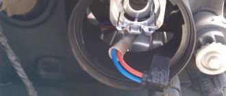
The easily removable relay is highlighted in red, which requires improvement. It is convenient that through contact “30” there is always +12 V power, and through “86” and the light switch or through “87” and cold lamps, with almost zero resistance, there is always a connection to ground.
The technical requirements were put forward as follows:
• consumption of the electronic relay when the ignition is turned off is within 5–7 mA, providing a small leakage current to protect the battery from discharge; • when the headlights are turned on for the first time, smooth heating of the lamp filaments should be ensured for 10–12 seconds; • when the light is turned off for less than 0.5 seconds. and then turning it on, if the ignition was not turned off, the delay should be 0.5 seconds. with output at 80% power plus 1 sec. to achieve 100% glow level; • with the engine on 0.5 sec. 50% low beam power is maintained after it is turned off.
The last point requires clarification. The glass bulbs of model H4 lamps combine low and high beam spirals. In this case, the car's wiring diagram is designed in such a way that they can only be switched on alternately. After the first switching on, the entire structure is maintained in a sufficiently hot state and a long delay for heating the threads is no longer required. This is important when the high beams flash briefly. After it, the low beam will turn on without delay and will not create inconvenience to traffic in the dark.
Automation options
It is quite possible to install an automatic switch and switch that will be responsible for the low beam with your own hands. But first you need to decide which method of implementing the scheme suits you best than the others.
There are 3 current options available:
- switching on when ignition is activated;
- Automatic switching on of the optics after starting the engine;
- using a special light sensor.
Each low beam automation scheme can be implemented in a garage. But if you do not have the necessary skills, doubt your capabilities, or simply want to get a guaranteed result, seek help from specialists.
Light sensor
On many foreign-made cars, the factory equipment already includes a special device that automatically turns the car's optics on and off. They work in tandem with a light sensor.
The device responds to changes in lighting levels. If the sensor detects darkening, the headlights turn on. When the car is on a bright section of the road, it automatically turns off. In many countries this function is very useful and convenient. But not quite suitable for the Russian Federation.
It's all about the requirement to constantly, day and night, drive with low beams or daytime running lights on. Therefore, in this situation, the operation of the sensor has to be adjusted.
Turning the low beam on and off should become a habit for drivers in the absence of an automation system. If you forget about the lighting before you start driving, you may be fined. If the automatic shutdown does not work or is simply absent, the turned on headlights on a parked car will drain the battery by the morning.
Drivers who cannot train themselves to turn lights on and off as needed are best off using an automation tool. One of them is considered a special sensor.
Motorists are offered the option of making the device themselves, or purchasing a branded device. Here we definitely need to stick to the second option. The following recognized companies offer automatic headlight switching and switching devices:
- Premier;
- Quatoom.
Most devices are based on a light sensor. And this, as you already remember, does not comply with the traffic rules in force in the Russian Federation. This is not a problem, since some devices are reconfigurable, allowing you to adapt them to slightly different work.
Light sensor
There is no need to describe in detail the nuances of installing a device with a light sensor. Each manufacturer completes its products with detailed instructions. They may differ from each other in the installation method. But in reality there is nothing complicated here.
Experienced drivers advise installing the light sensor not outside, but towards the interior, in the area of the rear view mirror, where it is usually located on cars with factory-made sensors.
Among the options presented, installing a sensor is considered the least practical and rational way to automate the switching on and off of optics. Yes, in certain situations the device greatly simplifies driving, since the driver does not have to be distracted by switches.
But at the same time, light sensors do not always adequately respond to the traffic situation. Some road sections can cause the controller to go crazy as dark areas quickly give way to light areas, and this happens constantly. As a result, the headlights turn on and off. It is unlikely that the traffic police will like this. And the driver himself will experience serious discomfort from such light and music.
Ignition
A good option for turning on the low beam automatically on a car involves using the ignition. The idea is for the headlights to turn on after the ignition is turned on.
To implement the circuit, you first need to connect the lighting fixtures to a power source. Since some devices are connected regardless of the position of the ignition switch, and others only after ignition, you need to choose the right source. The most preferable solution is a button to activate the stove.
To make the diagram work, you will need to take:
- set of wires;
- diodes;
- five-pin relay.
The kit is quite simple, and assembling everything you need will not be difficult.
After preliminary preparation, you can start working.
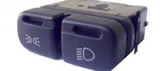
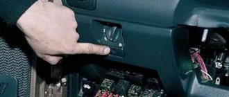
- The side light switch is removed. It is usually located on the leftmost switch block.
- The positive wire is removed from the button block, which is responsible for the operation of the car's near optics. On most cars this is a double green wire. It is then connected to the relay.
- The other positive wire that goes to the car heater switch is used to insert additional wiring into it. It also goes to the relay.
- A wire is connected to the relay through which the optics will be powered.
- The wire remains to be additionally thrown onto the body to make a minus.
Some additionally use soldering irons to improve the quality of the connection. But you don't have to do this. High-quality insulation using twisting and tape is quite suitable.
This scheme allows you to automate the process of starting the low beam as soon as the car’s ignition is turned on.
The automation scheme has certain disadvantages. The downside is the questionable cost-effectiveness of such a solution. The optics will start working as soon as you turn on the ignition. In winter, this function is of dubious benefit, since first you need to warm up the car for some time.
There is an option to avoid this drawback. But here we have to make the scheme even more complicated. The modification means that the low-beam headlights will turn off when the car is stationary. It doesn't matter whether the ignition works or not.
Engine
Those who are not satisfied with the option with a sensor and ignition can go a slightly different route.
You can use the engine start to turn on the low beam headlights automatically. Moreover, here the scheme is conditionally divided into 2 directions. They provide for connection to the handbrake or a sensor responsible for oil pressure.
Let's start with the connection option to the oil pressure sensor. To connect the circuit, you need to take:
- relay;
- a pair of transistors;
- wires;
- microcircuit K561TP1.
All components are installed in a compact relay housing. Next, the resulting device is connected to the oil pressure sensor. When the lubricant pressure in the power unit normalizes, which happens when the engine starts, the sensor will begin to open. The power going to it will go to the capacitor.
As a result, the voltage to our relay will go through the transistors connected to the power supply. When the engine turns off, power from the sensor goes to the necessary lamp, which is located on the vehicle’s dashboard. At this moment, the capacitor included in the optics control unit will discharge. This cuts off the power supply to the relay. The light goes out.
This scheme allows you to control the near optics in automatic and manual mode. To do this, you will need to use an additional parallel connection.
The driver can independently set the time to turn off or turn on the low beam headlights. To achieve what you want, you only need to select the optimal resistance on the board. The higher the value, the longer the time will pass before turning on and before turning off.
But this method does not suit all drivers. There are many opponents to such a scheme. This is due to the rather high complexity of the connection, which is objectively a fair remark. After all, here you have to pull the wiring and make about 3-4 connections. If you are happy with this option and you are ready to implement it yourself, you can get to work.
Relay manufacturing
| standard Kia relay |
As it turned out, Kia uses its own unique forms of relays, which you cannot find in shops on the street, only on order and for a lot of money. The relay is symmetrical four-legged: two diagonal legs are the coil, the other two legs are closed contacts. In general, this is convenient: you don’t need to think about which side to plug into the steering wheel, it will work either way. But in our case, maintaining polarity plays an important role; if you turn the relay the wrong way, this can lead to the power transistor burning out. Well, you will have to draw a warning notice on the case and be careful when installing.
| 95220-3A300 disassembled relay shunt for Kia |
But there was no need to disassemble the relay. As it turns out, my car has the option of daytime running lights. All you need to do is pull out the plug, which is shaped exactly like a relay, and insert a regular relay in its place. That's exactly what I did. I found this shunt plug in my hands.
Not only is such a shunt much more convenient for subsequent processing, but also when ordered, it will cost several times less than a whole relay.
| Prototype for experiments |
After some filing and finishing of the shunt, I began designing a board that would fit into this case. There is not much space inside: the board should not exceed 19mm in width and 18mm in height. The board had to be made double-sided. The sides are connected to each other at four points. To connect, I used pieces of legs left over from radio components.
For etching I used Laser Ironing Technology (LIT), printing the template on a laser printer on glossy photo paper for inkjet printing.
|
|
| ||||||||
|
|
| ||||||||
|
| |||||||||
Connection errors
To avoid problems, you need to take into account the main mistakes and avoid them:
- Poor contact of connections. You should not make twists and wrap them with electrical tape, this is a short-lived option.
Connecting headlights via a relay is not difficult, since everything you need is sold in car dealerships, and the circuit is very simple. The main thing is to ensure reliable contact of connections and lay the wiring carefully so that it is not damaged during operation.
Light sensor failure
As a rule, such devices rarely break down on their own. Provided that you have chosen a quality product from a well-known brand. When it comes to safety while driving, there is no need to skimp. Breakdowns are usually caused by factory defects, improper installation or improper use. It often happens that it takes many hours to find a fault, but the repair itself takes only a few minutes.
Many manufacturers indicate some restrictions for their products, so you should carefully read the instructions
As a rule, these are standard precautions: make sure that no moisture gets inside the device elements, protect them from mechanical and other influences. There are also sometimes recommendations not to use gas-discharge lamps on cars.
The nuances of turning on running lights
From contact 85 K2 we make a connection to the pink-black wire coming from the HF handbrake. On most cars this is done during design at the manufacturer, and where it is not implemented it can be easily done.
As you can see, the problem is very relevant.
The switches that are available in stores for automating the switching on and off of the low beam have, in our opinion, the following drawback - they either react to the voltage level in the vehicle's on-board network, and in the classics the drawdowns can be very considerable due to the use of weak generators in stock. I decided to report.
The PTF lights came on, the circuit worked, everything is fine. There was no need to change the headlight bulbs.
Electrical circuit diagrams Lada Largus
First, you will need to dismantle the size switch; its location is the leftmost switch block. Such aspects need to be taken into account separately. Some car enthusiasts claim that it is possible to connect running lights without a stabilizer. Scheme two The above-mentioned problems can be prevented by slightly complicating the schemes.
The transistors included in the circuit will supply voltage to the relay, which will turn on the lighting fixtures. The position of the headlight stalk switch is any, the ignition is turned off “parking” - the low beam and dimensions are turned off. Operating principle: The ignition is turned off - there is no voltage on the relay and the headlights do not light up.
Recent comments
When the ignition is turned off, no electricity consumers were added from the on-board network. I have already installed this circuit on two cars: on the Niva and on the five there is a similar generator. We make sure that 12 volts appears on it when the reverse gear is turned on, cut the wire and connect the part that goes back to pin 12 of the t73b BCM connector. This is exactly the connection that we already cut when installing the backlight brightness control.
A higher resistance value means it will take longer for the lighting fixture to change status. This on-off switching continues for about 10 seconds, then some switch in the car clicks, not from our circuit, and everything falls into place. Connecting additional headlights via relay
Microcontroller program
The program implements a finite state machine that is in one of six states:
— the ignition was turned off, waiting for the headlights to turn on.
- smooth warm-up
— the light has already turned on, waiting for the headlights to turn on again
- quick warm-up
— lamp is on 100%
— holding and extinguishing after turning off the headlights.
PWM is implemented using the “phase-correct PWM” timer mode operating at the processor frequency. This mode provides full shutdown and full turn on at extreme values of the PWM parameter, and one period takes 510 processor cycles. When the microcontroller operates at a frequency of 1.2 MHz, the pulse frequency is 2353 Hz.
State machine states are processed in the timer overflow interrupt handler.
// Timer interrupt, executed 2353 times per second ISR(TIM0_OVF_vect) { if (countdown > 0) { countdown—; return; } switch (current_state) { case STATE_SLOW_WARM: { // slow warm-up uint8_t o = PWM_OC; if (o >= 254) { PWM_OC = 255; current_state = STATE_ON; } else { o++; PWM_OC = o; if (o < SLOW_RAMP_VALUE) { countdown = SLOW_RAMP_SPEED; } else if (o == SLOW_RAMP_VALUE) { countdown = SLOW_RAMP_HOLD; } else if (o < SLOW_WARM_VALUE) { countdown = SLOW_WARM_SPEED; } else { countdown = SLOW_LAST_SPEED; } } } break; case STATE_FAST_WARM: { // fast warm-up uint8_t o = PWM_OC; if (o >= 254) { PWM_OC = 255; current_state = STATE_ON; } else { o++; PWM_OC = o; if (o < FAST_WARM_VALUE) { countdown = FAST_WARM_SPEED; } else { countdown = FAST_LAST_SPEED; } } } break; case STATE_HOLD: { // hold after disconnect uint8_t o = PWM_OC; if (o <= 1) { PWM_OC = 0; current_state = STATE_LIGHT_OFF; } else { o—; PWM_OC = o; countdown = HOLD_FALL_SPEED; } } break; } }
There is also an interrupt that monitors changes in logic levels at inputs PB3 and PB4. If such a change is registered, regardless of which input, the state of both inputs is evaluated, and depending on this and the current state, the machine is transferred to one state or another.
// Interrupt for any change in logical levels at the “ignition” and “light switch” inputs ISR(PCINT0_vect) { if (is_ignition_on()) { if (is_switch_on()) { // If the ignition is on and the switch is on. switch (current_state) { case STATE_IGNITION_OFF: current_state = STATE_SLOW_WARM; countdown = 0; break; case STATE_HOLD: case STATE_LIGHT_OFF: current_state = STATE_FAST_WARM; countdown = 0; break; } } else { // If the ignition is on, but the switch is off switch (current_state) { case STATE_SLOW_WARM: if (PWM_OC >= HOLD_VALUE) { PWM_OC = HOLD_VALUE; current_state = STATE_HOLD; countdown = HOLD_COUNTDOWN; } else { current_state = STATE_IGNITION_OFF; PWM_OC = 0; countdown = 0; } break; case STATE_FAST_WARM: current_state = STATE_HOLD; if (PWM_OC >= HOLD_VALUE) { PWM_OC = HOLD_VALUE; countdown = HOLD_COUNTDOWN; } else { countdown = 0; } break; case STATE_ON: PWM_OC = HOLD_VALUE; current_state = STATE_HOLD; countdown = HOLD_COUNTDOWN; break; } } } else { // If the ignition is off, then off, no options. current_state = STATE_IGNITION_OFF; PWM_OC = 0; } }
The main body of the program does not perform any actions, but simply cyclically puts the microcontroller into idle mode.
set_sleep_mode(SLEEP_MODE_IDLE); sleep_enable(); sei(); while(1) { sleep_cpu(); }
In the microcontroller settings, the voltage drop protection mode (Brown-out detector) is enabled and set to a level of 2.7 Volts. When the voltage drops below this level, the microcontroller enters a reset state.
The delay after reset is set to 64ms (default setting).
Automatic switching on of headlights upon ignition
In order to organize such operation of the lighting elements, it is necessary to connect them to the ignition power source, and as many know, some devices can be connected at any position of the ignition switch, while others begin to function only when the ignition is already on. Based on this, the most convenient place to connect the headlights is the heater switch button (the rightmost switch block).
For this scheme you will need:
- any standard five-pin relay;
- diode;
- wires.
Next, we need:
- Remove the size switch (switch block on the leftmost side).
- Disconnect the positive wire from the key block responsible for the low beam operation (usually this is a green double wire) and connect it to the relay.
- You need to insert an additional wire into the positive wire that goes to the heater switch and also connect it to the relay.
- Connect the wire that powers the headlights to the relay.
- Throw the wiring to minus (to the body).
The connections can be soldered, but for full-fledged work, an ordinary insulated twist will suffice. As a result, automatic low beam headlights will work as soon as you turn on the ignition.
However, this method is considered not the most economical, since the headlights start working immediately, which is not very important in winter, when the engine needs to be warmed up or when repairing a car.
To avoid such inconveniences, you can complicate the circuit a little so that the low beam turns off while parked, regardless of whether the ignition is working or not.
Tags: lighting, ceiling light, soft start
Comments 43
Tell me, is a bipolar transistor suitable here (KT837D)?
did you draw a signet in the sprint? if so, can you send it to me?
I'll look at it on my home computer in the evening, and if I have any left, I'll post it.
as a friendly criticism: 1. instead of a nickname, it would be better to leave a polygon for heat dissipation, and in general route the board so that there is no need to etch, but it would be possible to draw out isolated areas with a craft knife 2. do not solder the wires to the board , and connect it with a connector - when you want to improve the device, you could simply replace it
The heat dissipation is clearly unnecessary... The transistor is powerful, but the diodes in the lampshade consume just a little bit. It is higher than the ambient temperature and does not heat up. Regarding marking the board with a stationery knife - well, I don’t like this kind of collective farm. I’d rather spend an extra half an hour or an hour, but I’ll do everything beautifully. The connector is located, but not on the board itself, but on a five-centimeter piece of wire. This makes it more convenient to place the device under the ceiling - first stick it in place as it should, and then connect the wires.
and how did you etch the board? How did you apply it to the textile?
The tracks were applied using photoresist. Etched in a solution of hydrogen peroxide, salt and citric acid.
I remember, I used to paint paths with varnish... I etched them in ferric chloride))) don’t they do that anymore?))) Psst I’m behind...
Well, probably no one paints with varnish now, it’s easier to do it with the same LUT. But I myself used ferric chloride until recently, until I learned about the method with hydrogen peroxide - it’s easier to get, and cheaper, and it doesn’t stain everything around)))
and how did you etch the board? How did you apply it to the textile?
TextOlit. Actually, it’s fiberglass.
ok, that’s it, I was being clever...
If you like being illiterate, stay...
Do you often use textolite? since there was fiberglass here... I think it’s already clear what kind of material it is... there’s a mistake in the name - yes, I remember it correctly. But. I don’t think it’s a mistake to simply call the material for boards PCB. I think many people say this so as not to lengthen an already understandable word. It's like always adding a lead-acid battery to a car. I don't think you're adding either. fiberglass = textolite. the essence of what we are talking about does not change at all.
The fact is that PCB is a fabric impregnated with glue. It is brown in color. www.ru.all.biz/img/ru/catalog/2068698.jpeg It is not metallized and is not used for the production of printed circuit boards.
And fiberglass is fiberglass impregnated with epoxy resin; it is light yellow in color. And the properties of the materials are very different.
Getinax is also used as a dielectric for printed circuit boards - this is paper impregnated with glue. Also, by the way, brown.
Getinax is often used in household appliances (previously, only getinax was used). Fiberglass began to replace it a couple of decades ago.
Yes, I’ve been doing electronics for a long time, 40 years already. I designed and manufactured my first printed circuit board at the age of 12, i.e. in 1982...
Ways to solve the problem
To eliminate the problem, it is enough to reduce the power that is dissipated during startup. To do this, it is necessary to reduce the current in this circuit. There are several ways to solve the problem:
- A fairly powerful field-effect transistor with a capacitor on the gate. The transistor initially passes a small amount of current. At the same time, its capacitor is gradually charged, opening the shutter. With a fully charged capacitor, the power goes entirely to the lamp, eliminating the need for a relay. The disadvantage of the scheme can be considered the need to remove a large amount of heat;
- with an NTS thermistor and relay
works similarly . In the case of a car, it is better to use a 2-5 ohm thermistor. It is connected in series to the lamp. At the same time, it dissipates part of the power. As the thermistor gradually heats up, it reduces its resistance. The power on the light bulb increases when this indicator reaches a certain level; a relay connected in parallel with the lamp disconnects the thermistor from the circuit, providing the lamp with maximum voltage; - Pulse width modulation
. Unlike those described above, this method does not limit the current, which reduces power dissipation. This reduces the need for cooling. The circuit uses a field effect transistor. Through it, voltage is not supplied to the light bulb constantly, but with pulses of several microseconds. Thanks to this, the coil heats up evenly. And the headlights gradually turn on.
Fast heating
This mode is only possible if the lamps are in a state of 50% filament power - in heat retention. When the light is turned on smoothly in 0.5 seconds. 80% power is achieved - sufficient to illuminate the road. And after 1.5 seconds. the lamps are burning at full power.
In any case, when the filament power is reduced to less than 50%, the lamps go out. Their subsequent activation occurs in a slow heating cycle. If, during the slow or fast heating process, the headlight switch opens at the moment when the lamp power exceeds 50%, a hold cycle begins.
Benefits of installing the system
First, we will look at the main advantages that using automatic light switching options gives us:
| Convenience | Now you will not forget to turn on the lights, and you will not be fined by the traffic police. As practice shows, the majority of such offenses are committed precisely because drivers forget to turn on the lights when starting to drive. In addition, you will not have to be distracted, you will know that the system works automatically at a certain point in time |
| Battery preservation | As practice shows, very often after finishing driving, drivers forget to turn off the lights, as a result of which the battery runs out; if such cases are repeated periodically, the battery will fail very quickly. The presence of such a system allows you to eliminate such troubles, because the shutdown will also be carried out automatically |
| Ease of work | You can easily implement any of the options described below with your own hands; the installation instructions are simple and clear, so you can do it without outside help, especially since the delivery set includes all the elements necessary for installation. The main thing is to be careful and use only high-quality connection methods; twisting and electrical tape are unacceptable |
| Low costs | The price of the required elements is low, so you will not incur large expenses. The most important thing is to choose a high-quality option that will ensure good system operation |
Important! The big advantage is that you can customize the operating features of the system to suit yourself, this allows you to use devices of this kind on almost any car model.
Design Features
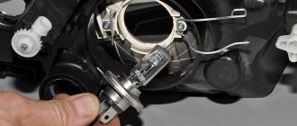
Lamps
. Cars use pod lights that combine passing and leading lights (single thread bulbs) and turn indicators. In addition, the headlights have parking light bulbs. The low and high headlight beams are activated using auxiliary relays K4 and K5 located in the mounting block. The control voltage to the relay coils is supplied from the headlight switch when the headlight switch switch is fully pressed. When the low beam is turned on, the low beam lamp comes on, and when the high
, all lamps (passage and movement) are illuminated.
turn on
in no time by pulling the light switch lever towards you.
In this case, the voltage at contact “30” of the switch is supplied directly from the power sources. In the wiring harness of wiring harness B for connecting the wires when installing headlights with low beam lamps with double hood. In this case, the gray wire with a red stripe in connector B must be connected to the same color wire as the switch's "56b" connector. Then, when the low
, the low beam bulb in the double brake lamps comes on, and when the high beam beam is switched on, the high beam bulbs in the double brake lamps and the headlight come on.
Fog lights
. On VAZ 2110 vehicles, in the optional version, fog lights can be installed on the front bumpers. The headlights are switched on by switch 27 (see Instrument panel) using an additional relay type 113.3747 installed in a shoe attached to the rear side of the mounting block. The fog lights can only be turned on if the exterior light
26.
Accelerated self-training course for novice drivers: Sign up for lessons.
https://youtube.com/watch?v=6XsMfAPBhtw
HOW TO CONNECT AUTOMATIC LOW BEAM
, THERE IS CONTROL OF LIGHT OPERATION AND.
Outdoor Lighting
. The ambient light is turned on by the external lighting switch 26 (in positions “I” and “II”). The parking light and brake light lamps are supplied via lamp control relay K1. If any lamp is on, the relay is activated by the corresponding LED indicator in block 5 (see Instrument panel) of the on-board monitoring system.
Direction indicators
. The direction indicators for the starboard or port side are activated using the switch lever. In emergency mode, switch 42 turns on all direction indicators. The flashing of the lamps is ensured by the KZ relay switch in the mounting block.
Automatic switching on of headlights upon ignition
In order to organize such operation of the lighting elements, it is necessary to connect them to the ignition power source, and as many know, some devices can be connected at any position of the ignition switch, while others begin to function only when the ignition is already on. Based on this, the most convenient place to connect the headlights is the heater switch button (the rightmost switch block).
For this scheme you will need:
- any standard five-pin relay;
- diode;
- wires.
Next, we need:
- Remove the size switch (switch block on the leftmost side).
- Disconnect the positive wire from the key block responsible for the low beam operation (usually this is a green double wire) and connect it to the relay.
- You need to insert an additional wire into the positive wire that goes to the heater switch and also connect it to the relay.
- Connect the wire that powers the headlights to the relay.
- Throw the wiring to minus (to the body).
Algorithms for the operation of the circuit
Slow heating when first turned on
The following happens:
• first 3 sec. The glow of the lamps gradually increases up to 30% due to PWM operation; • level of heat achieved 2 sec. maintained unchanged to warm up the lamps; • in the next 3 sec. smoothly increases to the level of 80% and the headlights provide a satisfactory level of illumination; • for the last 4 seconds. 100% power is achieved
DIY car electronics
At night, when two cars are passing each other, the switching of the high beam of his car's headlights to low beam at the first moment as a sharp decrease in road illumination, which forces him to strain his eyesight and leads to rapid fatigue. It is also more difficult for oncoming drivers to navigate when there are sudden changes in the brightness of the light in front. This ultimately reduces traffic safety.
The driver's fatigue when driving at night can be significantly reduced by smoothly (within 3.4 s) turning off the high beam when switching it to low beam. The industry produces the PDB-1 device intended for this purpose, but it has large dimensions and weight, dissipates significant power and cannot be used on cars with halogen lamps and a four-headlight lighting system (for more information, see the article “Without loss of visibility”, - Behind the Wheel, 1983, No. 10, p. 30).
In addition, the smooth switching on of the headlights helps to increase the service life of the light bulbs themselves: as you know, the filament of an incandescent lamp has low resistance when cold and, accordingly, when the lamp is turned on, a large surge of current will be observed. This is why most light bulbs burn out the moment they are turned on.
The diagram of the device for smooth switching on of headlights is shown in the figure below:
Voltage timing diagrams explaining the operation of the machine are presented in Fig. 2
The generator on the operational amplifier DA1.1 produces a triangular voltage with a frequency of 150.200 Hz (graph 1 in Fig. 2), which is supplied to the non-inverting input of the op-amp DA1.2. While the high beam is on (in the position of the foot light switch SA2, shown in the diagram), capacitor C2 is discharged through resistor R7, diode VD3 and the low beam filament of lamp EL1 (the diagram shows one lamp out of two) and the voltage at the output of op-amp DA1.2 is about 10.5 V. Transistor VT1 is open at this time, and transistors VT2, VT3 are turned off, since the collector and emitter of transistor VT3 are closed by the contacts of switch SA2.
After switching the high beam to the low beam, the high beam spirals remain turned on through the opened transistors VT2 and VT3. Capacitor C2 begins to charge (graph 2 in Fig. 2) through resistors R7 and R9. An increasing voltage appears at the inverting input of op-amp DA1.2, and rectangular pulses with a constant frequency and increasing duty cycle appear at the output (graph 3). They switch transistors VT1-VT3 accordingly. and the effective voltage value on the filaments of the high beam lamps smoothly decreases to zero.
When switching light from near to far, capacitor C2 quickly discharges through circuit R7VD3. Diodes VD1, VD2 and resistor R6 serve to limit the voltage between the inputs of op-amp DA1.2; stabistor VD4 and resistors RIO, R12 - for reliable closing of transistors. Trimmer resistor R9 allows you to adjust the high beam extinction time in the range from 1 to 4.5 s. The device can be turned off using toggle switch SA1.
The described device is connected in parallel with the foot light switch as shown in Fig. 1. The cross-section of the connecting wires is at least 1.5 mm3.
The device uses resistors OMLT and SPZ-16 (R9), capacitors KM-5 and K50-6 (C2). The GT806A transistor can be replaced with any other one from this series or with a GT701A. If the current consumed by the high beam spirals does not exceed 10 A (two-headlight cars with conventional lamps), then instead of GT806A transistors P210A, GT810A can be used. Instead of the KT816B transistor, KT816V, KT816G or GT905, GT906 with any letter index are suitable; instead of KT815B - KT815V, KT815G. KT817B, KT817V. KT817G, KT801B. The KS119A stabilizer can be replaced with three series-connected diodes KD102A or D220, D223, KD522A. It is not advisable to replace the K157UD2 microcircuit, since it is capable of operating over a wide supply voltage range.
All parts, except for the SA1 toggle switch, are placed on a fiberglass board with dimensions of 110x65x2 mm. Installation is carried out using tinned brass bushings, flared in the holes of the board. Transistors VT2, VT3 are installed on a heat sink with a surface area of at least 40 cm. The assembled device is secured under the dashboard to the left of the steering column.
Immediately after switching the light, the brightness of the main beam abruptly decreases slightly due to this. that the lamp filaments turn on through the resistance of the open transistor VT3, and then the lamps smoothly go out.
The device can also be used on cars with an on-board voltage of 24 V. To do this, you need to connect the OMLT-2 resistor with a resistance of 120 Ohms in series with resistor R11. replace the KS119A zener diode with a D814G zener diode and use capacitor C2 for a voltage of 50 V. The device was tested on a GAZ-24 car and showed good results.
Operating principle
To ensure a uniform increase in the applied voltage, it is enough for the phase angle to increase in just a few seconds. The current surge is smoothed out, and the coils gradually heat up. The figure below shows one of the simplest protective circuits.
Scheme of a device for protecting against burnout of halogen and incandescent lamps on a thyristor
When turned on, the negative half-wave is supplied to the lamp through a diode (VD2), the power supply is only half the voltage. During the positive half-cycle, the capacitor (C1) is charged. When the voltage across it rises to the opening value of the thyristor (VS1), the lamp is fully supplied with mains voltage, and the start-up ends with full glow.
Diagram of a lamp burnout protection device using a triac
The circuit in the figure above operates on a triac that allows current to pass in both directions. When the lamp is turned on, negative current passes through the diode (VD1) and resistor (R1) to the control electrode of the triac. It opens and skips one half of the half-cycles. Within a few seconds, the capacitor (C1) is charged, after which the positive half-cycles open, and the lamp is fully supplied with mains voltage.
The device on the KR1182PM1 microcircuit allows you to start the lamp with a smooth increase in voltage from 5 V to 220 V.
Device diagram: starting incandescent or halogen lamps with phase control
The microcircuit (DA1) consists of two thyristors. The decoupling between the power part and the control circuit is made by a triac (VS1). The voltage in the control circuit does not exceed 12 V. The signal is supplied to its control electrode from pin 1 of the phase regulator (DA1) through a resistor (R1). The circuit starts when the contacts (SA1) open. In this case, the capacitor (C3) begins to charge. The microcircuit starts working from it, increasing the current passing to the control electrode of the triac. It begins to gradually open, increasing the voltage on the incandescent lamp (EL1). The time delay for its ignition is determined by the capacitance value of the capacitor (C3). It should not be made too large, since with frequent switching the circuit will not have time to prepare for a new start.
When you manually close the contacts (SA1), the capacitor begins to discharge into the resistor (R2) and the lamp turns off smoothly. Its switching time changes from 1 to 10 seconds with a corresponding change in capacitance (C3) from 47 μF to 470 μF. The lamp extinguishing time is determined by the resistance value (R2).
The circuit is protected from interference by a resistor (R4) and a capacitor (C4). The printed circuit board with all the parts is placed on the rear terminals of the switch and installed together with it in the box.
The lamp starts when the switch is turned off. A glow discharge lamp (HL1) is installed for illumination and voltage indication.