Greetings! I finally rested after the holidays and decided to write a short article today. It happened on December 31st. It was such that we stopped for a short smoke break, and, of course, turned off the engine. This is where the problem lay, since we could not start the engine. After fiddling with the car a little, they diagnosed the cause as the ignition contacts, which had simply burned out.
As we looked into the situation in more detail, the specifics became more and more clear. Not only the contacts died the death of the brave, but also the capacitor. Here the old TV and its capacitor helped us, but we spat on the contacts and went in search of contactless ignition. Our city is quite provincial, and therefore it was simply unrealistic to purchase a ready-made set of the ignition we needed, which led to the purchase of the following components:
- Sensor – distributor (distributor);
- Switch for 6 contacts from eight or nine;
- Ignition coil from figure eight.
- I advise you to immediately buy ready-made wiring, but we were unlucky - alas, it wasn’t available in our store... I won’t write about prices, since they are different everywhere.
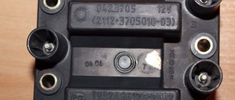
I’ll say right away that I won’t fully describe the process of installing contactless ignition on 3 and 6, there are a huge number of similar instructions on the Internet (when I have time, then I’ll write my own). So, the first problem awaited me, it was that the distributor was for a block from a penny. Although the inscription on the packaging said otherwise:
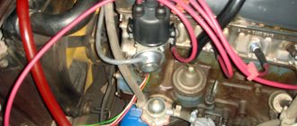
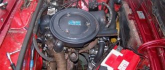
I wasn’t too upset, they just replaced it with a donor distributor shaft. Everything worked out. I would like to point out that this was an old R-125 distributor that did not have a vacuum ignition advancer (instead of which it had a manual octane corrector). Under the hood the elements looked like this:
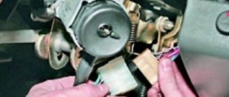
I almost forgot. Regarding the connectors of the distributor and switch. After a short search, we found the required connector in the wiring of the Volkswagen Jetta, after which we sawed off a piece of the distributor of the required size:
And of course for the switch:
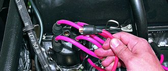
After everything was connected according to the diagram, we finally saw a spark and the engine started. The only thing left to do was to set the ignition correctly.
Along the way, another problem awaited us - the tachometer did not want to show the engine speed if it was less than 2000 rpm. To solve the problem with a break in the signal wire in the tachometer, a capacitor was included there (someone installs a capacitor from a standard contact ignition system, in my case the capacitor had a capacity of 0.25 uF 400V).
Did I feel any advantage? For starters, the engine started more confidently, and it ran more smoothly and steadily, plus the dynamics at high speeds increased significantly. The run-in is currently underway...
Some owners of classic cars of the VAZ 2101-07 family are constantly trying to improve, modify, add electronics and convenience. One of these improvements is the installation of contactless electronic ignition.
Which ignition is better: contactless or contact?
Contact ignitions are obsolete, but are still used in older cars. On rear-wheel drive VAZ models, contactless was first installed on 2107.
Let's look at the differences between contact and non-contact ignition:
Advantages of contactless ignition:
- since there is no contact group in the distributor, sparking occurs clearly;
- long coil life;
- at medium engine speeds, BSZ creates a spark 4 times more powerful than contact ignition. This is especially useful if the spark plugs are dirty, as a spark will still be produced;
- performs its functions perfectly even in cold weather;
- if the voltage in the electrical network is low, then sparking will still occur;
- thanks to the powerful, stable spark of the candles, the fuel-air mixture ignites faster;
- if BSZ is installed, then fuel consumption decreases and engine power increases;
- improved vehicle acceleration dynamics;
- BSZ is easier to maintain because the device has no moving parts.
How to set the ignition from scratch on a classic? A small instruction for carb cars.
I often look at forums and see that people are faced with such a problem as the initial angle of the ignition installation, for example, when replacing a distributor. What can I tell you about this replacement? Everything is done simply! So, let’s start with the fact that, for example, we overhauled the engine or simply changed the ignition system, as we read below on how to do this point by point. In the meantime, preparations: -
We will set up the fourth cylinder.
—
Don’t forget to tension the chain before setting the initial ignition angle or replacing the distributor.
This is easy to do, but there are 2 options... Option No. 1. Remove the valve cover, release the tensioner cap, turn the crankshaft by the ratchet nut using a wrench a quarter turn (90 degrees). With the cover removed, we can check the chain tension with our hands, and if the tensioner does not provide the required tension, then we can use a pry bar to tighten the shoe a little, and thereby mechanically tighten it a little more. It still won't work. The method is suitable for both a standard tensioner and a mechanical automatic tensioner of the pilot type (there are enough manufacturers, we won’t go deeper). Option #2. Well, let’s say we don’t want to remove the cover for some reason.
What do we do in this case? We release the tensioner cap, turn the crankshaft a quarter, tighten the cap, then loosen the nuts that hold the tensioner by no more than 2mm with a 10mm wrench, turn the crankshaft again a quarter and then tighten the nuts. Also suitable for both tensioner type options. So, the chain is tensioned, let's proceed further. First, we need to determine when the 4th cylinder is at TDC (top dead center). How to do this if, for example, we do not want to remove the valve cover or it has already been removed? Simply, when the cover is removed, you can determine the state of valves 7 and 8; they are pressed at the stage of the compression and spark cycle: -
We unscrew the spark plug from the 4th cylinder, plug the spark plug hole with a finger, or it’s better to insert a piece of newspaper into it (we crumple it up and stick it in so that our plug doesn’t leak).
—
We begin to turn the crankshaft by the ratchet nut.
—
As soon as we feel with our finger that the pressure is increasing, or the piece of paper knocks out, it means the piston is approaching TDC and the valves are closed.
—
We check where the pulley mark is located and bring it to the second mark on the front engine cover.
—
We insert the distributor so that the slider faces the contact of the fourth cylinder (number 4 is stamped on the cover).
Those. We place the body as we want, but we rotate the shaft to the desired position, check the cover and, if necessary, bring the slider into contact by turning the body. —
We tighten the distributor.
That's basically it, the initial angle is set, then we start the engine, warm up and then adjust it for speed. There are only 2 points here: 1
Appropriate for “low” blocks (01, 011, 05), we accelerate to 40 km/h according to the speedometer on a flat section of the road, put in 4th gear and press the gas to the floor.
It should “ring” (detonation, difficult to confuse) up to 48-54 km/h. If we correct anything. 2
Applicable for “high” blocks (03, 06, 213), accelerate to 47-50 km/h, engage fourth gear and gas to the floor. It should “ring” up to 55-58 km/h no more.
If it rings loudly and almost all the time or is audible in other gears, then it means the ignition is early, you need to release the distributor and turn it clockwise (from the head to the expansion tank), if it doesn’t ring at all, then turn it counterclockwise towards the head. Turn no more than one notch on the bottom of the distributor body (pay attention to the marks). For convenience, use a marker to mark the block under the distributor body.
Why is this so? It’s just that for “low” blocks the compression ratio (hereinafter referred to as CL) is 8.8, for “high” CL = 8.5 (I’m writing everything for the stock options without taking into account the head wash and modernization of the blocks). If we push off from 40 km/h on different engines, then we won’t hit the ignition in any way, it may happen either later or early. So I just advise you to stick to this description.
Why this is so, and not otherwise, is simply an established practice. It is also worth taking into account the errors in speed readings! If previously there were 3 variants of the speedometer drive on sale, which could be distinguished by the colors of the paint on the body (except for the teeth), now only blue is on sale (previously: red - for a gearbox with a gear ratio of 4.1, blue for 3 .9, without paint under 4.3. I hope I didn’t mess anything up). Those. in our time with a blue speed sensor (the only one I’ve seen on sale) with any gearbox and 4.1 gearbox - we get a speed error of 10 km/h (the speedometer shows 100 km/h, but we’re actually driving 90 km/h), with box 2105 and gearbox 3.9 - shows 100 km/h, but the real one is 95 km/h. Well, in general something like this. There are no photos, I hope I described it well. If you write anything.
Source
Non-contact ignition system device
The BSZ device for carburetor engines consists of:
- Distributor. This is a device that is responsible for creating a spark at the right moment. It is also called the ignition system distributor.
- High voltage coil. This element in the ignition system receives low voltage from the battery, converts it and supplies high voltage. Therefore, high-voltage wires come from it. The coil consists of two windings. The primary one is made of a large cross-section wire (connected to the electrical part of the car via the ignition switch relay), the secondary one is made of many turns of thin wire (connected with a high-voltage wire to the distributor).
- Switch. This element of the contactless ignition system is responsible for the formation of a spark. In simple words, a switch is a signal amplifier. The switch is only available in the ignition system of internal combustion engines with a carburetor. By the way, SOLEKS is considered the best carburetor. On injection VAZ 2107, as well as on others, a switch is not needed, since its functions are performed by the on-board computer controller.
- High voltage and normal wiring. High voltage wiring must meet heavy insulation requirements.
- Terminals. Serve for connections and must be strong.
Electronic and contactless ignition systems are the same device. It got its name due to the absence of a contact group in the system design. The ignition switch also has a contact group, which is a common cause of engine failure.
Distributor device:
- frame;
- shaft;
- cam;
- moving contact (slider).
When ignition adjustment is required
Correctly setting the ignition of the VAZ 2106 improves the ease of starting the car engine, the dynamics and life of the power unit. It must be carried out after:
- overhaul of the engine or operations associated with partial disassembly of the engine;
- camshaft reinstallation;
- valve burnout;
- replacing cylinder block gaskets, timing chain/belt.
What happens if there is no adjustment?
Contactless ignition is one of the most popular methods of tuning domestic cars. Photo: vaz-remzona.ru
If the ignition is advanced, a metallic sound will appear when the engine is running, the engine will run unstably, the idle speed will “float”, the traction force will drop, and excessive fuel consumption will occur.
With late ignition, the engine's throttle response decreases, the engine becomes coked with carbon deposits, as a result of which it quickly heats up. To accelerate the car, you need to press the gas pedal hard.
The consequence of an incorrectly set ignition is premature wear of the cylinder-piston group, engine jamming due to overheating and failure of vehicle components.
How to properly adjust the ignition yourself
Ignition adjustment can be done in a repair shop using a strobe light or independently. Among the tools and equipment you will need a crankshaft wrench, a “13” wrench, and a 12 V test light, which can be replaced with a voltmeter. First, unfasten the latches and remove the distributor cap. At the first stage of work:
- Disconnect the (–) battery terminal.
- With the power unit not running, set the piston of the first cylinder to the position corresponding to the compression phase (spark jump) before top dead center.
- To do this, unscrew the spark plug of the first cylinder and plug the hole in the cylinder head with a finger.
- By turning the crankshaft with a wrench, we select a position in which the air will push the pin out of the hole.
- We combine two marks: on the pulley and the timing cover. The latter has long (0°), medium (5°) and short (10°) marks, indicating different ignition timing. It is necessary to align the mark with the middle timing mark, which means setting the ignition timing to 5°.
- Screw the spark plug back in and connect the high-voltage cable.
At the second stage of work, we determine the ignition timing:
- Connect the (–) terminal of the battery.
- Use a wrench to loosen the nut on “13” securing the distributor.
- Using alligator clips, we connect one end of the control lamp to ground, and connect the other end to the low-voltage wire of the bobbin.
- We connect the central wire of the breaker to ground.
- Turn the ignition key to position “I”, the indicator light will light up.
- Very slowly turn the distributor housing clockwise until the light turns off.
- Turn the distributor slider counterclockwise until the lamp turns on.
- Having fixed the position of the mechanism with one hand, tighten the distributor fastening nut with the other hand.
If you prefer visual instructions, check out this video:
A quick way to set the ignition “by ear” in emergency situations
In unforeseen circumstances, it may be necessary to adjust the ignition on the road. To do this, set the choke (carburetor air damper) to approximately 2000 rpm on a running internal combustion engine. engine. Loosen the distributor fastening and rotate the housing alternately in both directions. Listening to the sound of the engine, we select the optimal position of the distributor. The power unit must develop the maximum speed and operate without “failures”. We fix the distributor in the found position.
Electronic ignition connection diagrams: VAZ 2101-VAZ 2107
Scheme of a contactless ignition system for VAZ cars:
How contactless ignition works
The sequence and principle of operation of the BSZ is as follows:
- The driver turns the ignition key.
- The circuit is closed and constant voltage from the battery is supplied to the primary winding of the ignition coil. The energized primary winding forms a magnetic field around itself.
- When the starter starts, it begins to rotate the crankshaft of the internal combustion engine and rotates the shaft, which is located inside the distributor along with the slider.
- The hall sensor detects how the distributor shaft rotates (along the protrusion on the shaft) and transmits a signal to the switch.
- The electronic unit turns off the voltage supply to the primary winding based on the signal from the Hall sensor.
- When the voltage supply circuit is interrupted, at that moment a high voltage pulse of up to 24 kilovolts appears in the secondary winding of the coil, which is transmitted through a thick wire to the slider (the moving part of the distributor).
- Fixed contacts are built into the roof. The runner throws an impulse onto one of these stationary contacts. From the contact that received the high voltage pulse, it is transmitted through high-voltage wires to the spark plugs of those cylinders in which the pistons are at top dead centers.
- When voltage is applied to the spark plug, the working combustion chamber of the cylinder already contains fuel and air in a compressed state for ignition.
- The distributor slider rotates to spark all spark plugs according to a certain sequence pattern: 1-3-4-2. Depending on how to install the slider, the entire operation of the system depends, early ignition or later, we learned to determine in another material.
- The car engine starts.
ECMs are sometimes interchangeable, but sometimes they are not repairable.
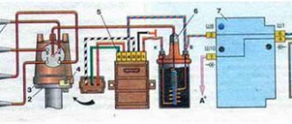
Diagram of an outdated VAZ ignition system (without switch)
1 — distributor (distributor); 2 - breaker; 3 - capacitor; 4 — ignition coil (bobbin); 5 - battery; 6 — ignition switch; 7 - spark plugs.
Checking the ignition coil
The coil is checked based on two indicators: the presence of a short circuit and an open circuit. Before diagnostics, the ignition coil must be disconnected. After this, one probe of the device is connected to the central contact of the coil, the second to the body (ground). If the display shows resistance equal to infinity, there is no short circuit.
The primary winding of the coil for a break occurs differently. The probes of the device must be connected to the right and left contacts. The resistance between them should be within 3-3.5 Ohms.
If the resistance of the primary winding does not correspond to the norm or there is a short circuit in the coil to the housing, it must be replaced.
Source
Selection of BSZ
When purchasing a new BSZ, you should pay attention to the presence of the components of the entire kit. The factory kit should contain:
- Distributor (main distributor). The code for engines 1.5 and 1.6 is 38.37061. For 1.3 engines, the number will be 38.3706–01, because the height of the 1.3 engine block is lower and the distributor shaft is shorter.
- Switch number 36.3734 or 3620.3734.
- High voltage coil (reel). Marking 27.3705
- Thin wires with connectors.
In appearance, the BSZ kit for the VAZ 2121 NIVA is very similar. But it’s better not to install this kit on a VAZ 2107 or a VAZ 2106, because the characteristics of the “six” and “seven” are very different from the “Niva”. Distributor brands for Niva: 3810.3706 or 38.3706–10.
The best manufacturer of electronic ignition systems for old VAZ cars is. The production capacity base is located in the city of Stary Oskol. According to reviews from car owners of classic BSZ SOATE models, this is an excellent option.
How to check the set ignition
When all the steps have been completed, you need to check the result in motion. Here's the procedure:
- The engine should warm up to about 90 degrees.
- Accelerate the speed to 40 km/h, then move the selector to 4th speed.
- While pressing the gas, listen to how the engine works. If the ignition is set correctly, the engine runs smoothly and the engine speed increases. When the valves knock, turn the distributor clockwise about 1.5 degrees.
- Carry out this operation until the extraneous sounds disappear.
- When the speed begins to drop sharply, turn the distributor by the same angle in the opposite direction.
Checking and adjusting the lead angle
To check whether the ignition is set correctly, just align the marks on the crankshaft pulley and the timing cover. In this case, the slider should be directed to the 4th cylinder, and the contacts should be open. If the slider “looks” towards the first cylinder and the car does not start, then turn it 180° as described above.
To create optimal fuel combustion conditions in the chamber, the flash should occur a little earlier than the piston reaches TDC. There are 3 ways to achieve this:
The advance angle is adjusted by turning the distributor housing
Reference. The second method is most often used by experienced drivers, since it gives a positive result without any instruments. The ignition distributor is turned until the position of the most stable engine operation is found. That is why the use of a light bulb does not play a big role, because the real advance angle at which the engine operates in optimal mode lies in the range of 5-10° and is determined individually in each car experimentally.
Once the settings are complete, press the gas pedal sharply several times. If you can hear the piston pins knocking (a ringing sound is clearly audible from the engine), then the advance angle is too large. Loosen the distributor and turn it 1-2° clockwise, then check again by pressing the accelerator.
Advice. Finger tapping is often heard when you fill with low octane fuel. Then it is necessary to reduce the advance angle so that detonation (which causes knocking) does not destroy the piston group. When using high-quality fuel, the angle should be increased in order to improve the dynamic characteristics of the VAZ 2107.
Preparatory stage
To set the ignition on a VAZ 2107 car, no special conditions are required; the operation can be done both in the garage and on the street, including in winter. For work, prepare the following set of tools:
- flat screwdriver;
- metal probe 0.35 mm thick;
- open-end wrench size 13 mm;
- a car light bulb designed for a voltage of 12 V with wires soldered to it;
- a wrench with a long handle designed to turn the crankshaft;
- key for unscrewing spark plugs.
Ignition tuning tool
Note. Instead of a special key to rotate the crankshaft, you can use a regular open-end wrench measuring 36 mm. If you don’t have such a key, then you will have to set the marks in the old proven way: by engaging 4th gear and raising the rear wheel, turn it manually, thereby turning the crankshaft.
Ideally, it is better to have in your arsenal a device for setting the ignition on a running engine - a strobe light. It is equipped with a lamp that flashes simultaneously with the moment of spark formation in the cylinder, which allows you to see the position of the notch on the crankshaft pulley at idle speed and clearly adjust the advance angle.
This is what a strobe looks like, which is convenient for adjusting ignition timing
Important point. The ignition is set in order to ensure that the spark appears in a timely manner and the engine starts, after which additional adjustments will be required. But the latter will not bring you the desired result when there is no compression in the cylinders or problems with the carburetor make themselves felt. If these faults are not eliminated, the engine operation will remain unstable, no matter how you configure the spark generation system.
Hence the conclusion: you can set the ignition correctly at any time, but to set it well - only on a working engine and carburetor.
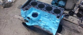
Design of VAZ 2103 and VAZ 2106 engines
Design of VAZ 2103 and VAZ 2106 engines
VAZ 2103, 21061, 2106, 2121, 21053, 2107 cars are equipped with VAZ 2103 and VAZ 2106 engines. They are of the same design, but with different cylinder capacities. They differ mainly in the dimensions of the cylinder block, pistons, and the length of the timing chain (116 links); there is also a difference in the shape of the tensioner shoe, or more precisely in the location of the tensioner thrust bracket on it due to the difference in the weight of blocks 2101, 21011 and 2103, 2106 The last blocks are 9 mm higher than the first ones, so the engines use chains of different lengths and different shoes. On engines 2101,21011 the tensioner shoe is marked 2101, and on engines 2103,2106 it is marked 2103.
At the bottom of the cylinder block there are five supports for the main bearings of the crankshaft with thin-walled steel-aluminum liners (Attention: when installing the liners, it is mandatory that liners with circular grooves on the inside are installed in the block at the point of contact in the crankshaft for continuous lubrication of the connecting rod liners when the shaft rotates, in the covers smooth liners without grooves are installed. The liners of the middle - 3rd journal are wider than the others and both are smooth, the rest are the same width.) The holes for the crankshaft bearings in the cylinder block are machined together with covers, so the bearing covers are not interchangeable, and to differentiate on their outer There are risks on the surface.
In the front part of the cylinder block there is a cavity for driving the gas distribution mechanism, closed by a cover in which the front crankshaft oil seal is installed. On the rear side, a rear cover with a crankshaft oil seal is attached to the cylinder block. On the left side of the block there is a drive shaft for auxiliary units (pig). Steel-aluminum bushings are pressed into the holes for the roller bearings. (Attention: currently bushings are produced from a copper-plated material of the corresponding color; when installing them, it is not allowed to install them too tightly, unlike steel-aluminum ones, since biting is possible when the engine heats up and the pin on the pig is cut off as a result of a violation of the timing belt installation and bending of the block head valves, except for engines on which pistons 2105 are installed in sizes 79.00; 79.4; 79.80; 80.00.
The cylinder head is common to four cylinders and is cast from aluminum alloy. Cast iron seats and valve guides are pressed into the head. Spiral grooves for lubrication are cut into the holes of the guide bushings. To reduce the penetration of oil into the combustion chamber through the gaps between the bushing and the valve stem, metal-rubber oil deflector caps are used. The cylinder head is attached to the cylinder block with eleven bolts. Between the head and the cylinder block there is a gasket made of asbestos material on a metal frame and impregnated with graphite.
The pistons are made of aluminum alloy. The piston skirt is oval in cross section and conical in height. In addition, steel temperature control plates are cast into the piston bosses. All this is done to compensate for the uneven thermal deformation of the piston when heated. The piston bosses have holes for oil to pass to the piston pin. The hole for the piston pin is shifted from the axis of symmetry by 2 mm to the right side of the engine to reduce the knock of the piston when passing through TDC. Therefore, near the hole for the piston pin there is a “P” mark, which during assembly should face the front of the engine. Pistons, like cylinders, are sorted into five classes by outer diameter every 0.01 mm, and by diameter of the piston pin hole - into three categories every 0.001 mm, designated by numbers 1. 2, 3. Piston class (letter) and hole category under the piston pin (number) are stamped on the bottom of the piston. Pistons in terms of weight in the same engine must be selected with the maximum permissible deviation (2.5 g).
Piston panels are made of cast iron. The outer surface of the upper compression ring is chrome-plated to increase wear resistance and has a barrel-shaped generatrix to improve run-in. The lower compression ring is scraper type (with a groove along the outer surface), phosphated. The ring must be installed with the groove down. The oil scraper ring has slots for oil removed from the cylinder and an internal coil spring (expander). The connecting rods are steel, forged, with a split lower head in which the connecting rod bearing shells are installed. The connecting rod is processed together with the cover, so when assembling, the numbers on the connecting rod and the cover must be the same. The crankshaft is five-bearing, cast iron. The shaft journals are hardened by high frequency currents to a depth of 2-3 mm. At the rear end of the crankshaft there is a seat for the front bearing of the gearbox input shaft, along the outer diameter of which the flywheel is centered. The flywheel is installed on the crankshaft so that the mark (a cone-shaped hole near the toothed rim of the flywheel) and the axis of the connecting rod journal of the first cylinder are in the same plane and one at a time from the axis of the crankshaft. The main and connecting rod bearing shells are thin-walled, steel-aluminium. All connecting rod bearings are the same and interchangeable. The upper shells of the 1st, 2nd, 4th and 5th main bearings are the same, with a groove on the inner surface, and the lower shells are without a groove. The shells of the 3rd main bearing differ from the others in their larger width and the absence of a groove on the inner surface. The gas distribution mechanism ensures that the engine cylinders are filled with a combustible mixture and exhaust gases are released in accordance with the cylinder operation order and valve timing adopted for the engine. The mechanism parts include: camshaft, valves and guide bushings, springs with fastening parts, valve drive levers. The camshaft, which controls the opening and closing of the valves, is cast iron. The rubbing surfaces of the cams are bleached. This process consists of electric arc melting of surfaces, which results in the formation of a layer of so-called “white” cast iron, which has high hardness. The shaft rotates on five supports in a special housing, and is kept from axial movements by a thrust flange placed in the groove of the front support journal of the shaft.
The valves (intake and exhaust) are located in the cylinder head obliquely in one row. The intake valve head has a larger diameter for better cylinder filling, and the operating chamfer of the exhaust valve, which operates at high temperatures in the aggressive environment of exhaust gases, has a heat-resistant alloy overlay. The springs press the valve to the seat and do not allow it to come off the actuator lever. The upper support plate of the springs is held on the valve stem by two crackers, which when folded have the shape of a truncated cone. The levers transmit force from the camshaft lobe to the valve. The lever rests on the spherical head of the adjusting bolt with one end, and on the end of the valve with the other. The adjusting bolt is screwed into the bushing and locked with a locknut. Drive of auxiliary units. The engine auxiliary components and timing mechanism are driven from the crankshaft using a chain drive. It consists of a double-row bush-roller chain of the “Gall” type. the drive sprocket on the crankshaft, the camshaft driven sprocket, the chain guide and the tensioner with shoe. The tensioner shoe and chain guide have a steel frame with a vulcanized rubber layer. When the locking nut is unscrewed, the chain is tensioned by the shoe, which is acted upon by springs through a plunger. The tensioner shoe rotates around the mounting bolt. After tightening the nut, the rod is clamped by the antlers of the cracker, as a result of which the chain tensioner spring is blocked.
When the engine is running, only the internal spring acts on the plunger, which, thanks to a gap of 0.2-0.5 mm in the tensioner mechanism, provides compensation for chain vibrations. The chain damper dampens vibrations of the leading branch of the chain. When the engine is running, the chain is stretched. It is considered operational if the tensioner ensures its tension, i.e. if the chain has stretched no more than 4 mm. The drive shaft of the oil pump, ignition distributor and fuel pump is installed along the engine and has two support journals, a helical gear and an eccentric, which drives the fuel pump through a pusher. The shaft helical gear meshes with a gear that drives the ignition distributor and oil pump.
The gear rotates in a cermet bushing pressed into the cylinder block. The gear has a splined hole into which the splined ends of the ignition distributor and oil pump rollers fit. Engine operation. During one working cycle, four strokes of hot mixture intake, compression, power stroke and exhaust gases occur in the engine cylinder. These strokes are carried out in two revolutions of the crankshaft, i.e. each stroke occurs in half a revolution (180) of the crankshaft. The intake valve begins to open 12 minutes before the piston approaches top dead center (TDC). This is necessary to ensure that the valve is fully open when the piston goes down. The valve closes 40 after the piston passes the bottom dead center (BDC).
Due to the inertial pressure of the jet of the sucked-in combustible mixture, it continues to enter the cylinder when the piston has already begun to move upward, thereby ensuring better filling of the cylinder. The exhaust valve begins to open 42 before BDC. At this moment, the pressure in the cylinder is still quite high, and gases begin to flow intensively out of the cylinder. The valve closes 10 minutes after the piston passes TDC. There is a moment (22 turns of the crankshaft near TDC) when both intake and exhaust valves are open simultaneously. This position is called valve overlap.
Signs of incorrect ignition on VAZ cars
Setting the ignition timing on a vehicle is necessary if the internal combustion engine is being repaired or the distributor is being dismantled. Also, during operation, it undergoes wear and tear, like any other engine systems, and accordingly the following signs of malfunction may appear:
- The motor does not start or has interruptions in operation. Provided that the combustible mixture is supplied correctly, the malfunction may be an incorrect setting of the advance angle, slipping or stretching of the timing chain.
- Poor acceleration and inelasticity of the engine. This means that the combustible mixture is not ignited at the required piston stroke position, which leads to a deterioration in the efficiency of the internal combustion engine.
- High gas consumption. This effect occurs under conditions of late ignition. Part of the combustible mixture does not have time to burn and flies out into the exhaust manifold. In such cases, you can hear characteristic popping noises in the exhaust while the engine is running.
Hard work of the internal combustion engine. This occurs under conditions of early ignition, when the working mixture ignites when the piston position has not reached top dead center.
In such cases, you can hear a characteristic ringing sound in the engine. Such symptoms can lead to burnt out exhaust valves.