01/26/2022 25,596 GAS
Author: Ivan Baranov
Every car enthusiast knows that the ignition system in any car is needed to ignite the combustible mixture in the engine. GAZ trucks are no exception. In this article, we propose to find out what the ignition procedure for the GAZ-53 is, what malfunctions a car enthusiast may encounter, and how it is configured.
[Hide]
Parts and spare parts, maintenance, service and repair
GAZ cars
ZIL cars
KAMAZ vehicles
MAZ cars
KRAZ cars
URAL cars
- URAL-4320, 5557
- Engine YaMZ-236
- __________________
- MAP OF SITE
Ignition system for GAZ-53, 3307 cars
The ignition system of GAZ-53, GAZ-3307 is a battery-based, contactless transistor with a voltage in the primary circuit of 12V, consists of electric current sources, an ignition coil, an additional resistor, a switch, an ignition distributor, spark plugs, spark plug tips, an ignition switch and low and low voltage wires. high voltage.
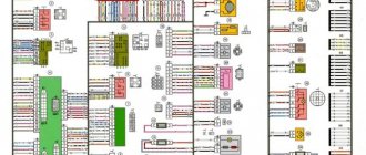
Fig.1. Diagram of the ignition system GAZ-53, GAZ-3307
A - to the starter; 1 - ignition coil; 2 - primary winding; 3 - secondary winding; 4 - battery; 5 - current indicator; 6 - additional starter relay; 7 - additional resistor; 8 — ignition and starter switch; 9 - noise suppression resistor; 10 — spark plug; 11 — distributor-sensor; 12 — interference suppression resistor of the slider; 13 — distributor winding; 14 - permanent magnet; 15 - switch; R1 - MLT-8.2 kOhm resistor; R2 - MLT-1 resistor, R3 - MLT resistor; R4 - MLT-82 kOhm resistor; R5 - MLT-62 Ohm resistor; R6 - MLT-200 Ohm resistor; R7, R8 - MLT-47kOhm resistors; C2 - capacitor K73-17-250V-0D; SZ - capacitor K73-17-4008-1; C4, C5—capacitors K73-17-250V-0.047 µF; C6 - capacitor K50-29-160V-10; C7 - capacitor KL-2-I20-500V-1000; VI - diodes KDYu2BiliKD4 521A; V2 - diodes KD209A or KD212A; V3 - transistor KT 848 A; V4, V5 - transistors KT630B or KT653B; V7 - diode 102B
Reliable and economical engine operation depends on the uninterrupted operation of the GAZ-53 ignition system. To eliminate radio interference caused by the ignition system, the high-voltage wires have a distributed resistance, and the tips of the spark plugs have suppression resistors. The ignition system diagram is shown in Fig. 1.
Technical characteristics of the ignition system of GAZ-53, GAZ-3307 cars
Ignition order of GAZ-53 - 1 - 5 - 4 - 2-6 - 3 -7 - 8 Type of ignition distributor (distributor) - 24.3706 Distributor shaft rotation speed per 1 minute with uninterrupted spark formation when working with a B116 ignition coil on a three-electrode spark gap with a spark gap of 7 mm, min-1 - 20 - 2300 Direction of rotation of the ignition distributor shaft (distributor) - clockwise Ignition coil - B116 Spark plugs - A11 Spark gap size in spark plugs, mm - 0.8 - 0.95 Additional resistor — 14.3729 Switch — 13.3734 or 13.3734-01 Spark plug tip — 35.3707200 Tip resistance, kOhm — 4 — 7
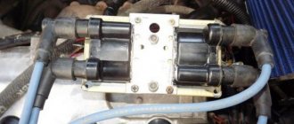
The ignition coil GAZ-53, GAZ-3307 (B 116) is used to convert low voltage current into high voltage current.
The B 116 ignition coil is a transformer, on the iron core of which the secondary winding is wound, and on top of it is the primary winding. The core with windings is installed in a sealed steel case filled with oil and closed with a high-voltage plastic cover.
Winding resistance at a temperature of 15 - 35 ° C: primary 0.43 Ohm, secondary 13,000 - 13,400 Ohm.
Maintenance of ignition GAZ-53, GAZ-3307
To protect against possible breakdown of the plastic cover, the coil must be cleaned of dirt, dust and oil, and the high and low voltage wires must be checked for secure fastening.
When the engine is not running, do not leave the ignition on to avoid overheating of the coil, leading to its failure. The use of other types of ignition coils is unacceptable.
The causes of ignition coil malfunction may be: insulation breakdown; turn-to-turn short circuit; chips and cracks in the plastic cover; burnout of the cover and ignition coil due to the high-voltage wire not being sent to the socket.
Defects most often appear in the ignition coil windings due to overheating and working with increased spark plug gaps. Overheating occurs mainly when the ignition is on and the engine is not running.
Before removing the ignition coil of GAZ-53, GAZ-3307 for replacement, you should make sure that the wires are connected to the coil terminals in good condition and securely. The coil should be checked on a special stand together with a transistor switch, an additional resistor and a distributor.
A working ignition coil should ensure uninterrupted sparking on a three-electrode needle gap with a spark gap of 7 mm from 20 to 2300 min"1 of the distributor roller and an ambient temperature of 25 ° C. If the coil does not meet these requirements, it should be replaced.
Useful tips
The ignition system of the GAZ 53 vehicle requires periodic inspection. It is necessary to check the quality of fit of high-voltage wires into the sockets of the coil and distributor. If there is a weakening of the contact, then you need to unbend the wire connectors and insert them into the sockets until they stop. A breakdown of the ignition coil is most likely if it is covered with a layer of dust, dirt or in water. Therefore, this should be avoided if possible. Leaving the GAZ 53 with the ignition on and the engine not running can lead to a breakdown of the coil.
The fact is that there is always voltage in the primary winding when the ignition is on and the engine is not running, because the breaker sensor does not work. When purchasing new spark plugs, it is advisable to install those recommended by the manufacturer, having first checked the gap between the electrodes. Adjust it if necessary. Replacing elements with new ones with different markings may lead to failure of other components of the system. It is necessary to periodically lubricate the distributor shaft through the existing oiler.
Electrical diagram
First of all, we note that any electrical circuit of a car, including one like the GAZ 53, is equipped with the following elements:
- GPT – alternating current generator;
- KTS – contact-transistor ignition system;
- start heater;
- wiring of different voltages connecting all elements into a single circuit.
Attention. The electrical circuit of the GAZ-53 truck is not designed for non-standard loads. Therefore, it is forbidden to start the engine if the cable running from the generator to the regulator is damaged or if it “sparks”.
Ignition system
Let's first consider the ignition system. It is known that it is battery operated, with a circuit voltage of 12 V.
It also consists of the following components:
- switch;
- sources supplying current;
- coils;
- resistor (additional);
- ignition distributor (distributor);
- candles with their tips;
- ignition switch;
- wiring.
Note that the smooth operation of the engine directly depends on the normal functioning of the ignition system. To avoid radio interference caused by the ignition system, the wires are equipped with a resistance distributor (this mainly applies to HV wires), and the tips of the spark plugs are equipped with suppression resistors. (See also the article Features of the GAZ wiring diagram.)
Let us now consider each element of the ignition system separately and find out how it functions.
- Spark plugs for GAZ 53 must have a factory gap of 0.85 mm. They must have a nichrome electrode - A11, A11-1, A10-H and others are suitable. The ignition order can be seen in the photo below.
- The ignition distributor is used in this car so that the rotation speed of its roller is one minute with uninterrupted sparking. Functions simultaneously with the ignition coil. The roller must rotate clockwise.
- Ignition coil - B114-B or B116 (more advanced). Generates high voltage pulses in the ignition system of a GAZ 53 car. It has a rated voltage of 12V and a secondary voltage of 17kV.
- The ignition switch amplifies the signal from the distributor sensor and the ignition coil. (See also the article Gazelle wiring diagram: how to install it yourself.)
Note. To connect all of the above parts and assemblies of the vehicle's electrical equipment into a single circuit, low voltage wires are used. They must be protected with polyvinyl chloride insulation.
Wiring
The basic rules that are followed when working with wiring are as follows.
- Careful attention is always paid to the wiring of the GAZ 53, which may be subject to various influences. If the insulation of any wire is broken, its metal component may touch the car body, thereby causing a short circuit. There is no need to say what this leads to (burning of insulation, fire, etc.).
- It is important to take into account the fact that the wires, no matter how well they are insulated, are always subject to mechanical stress during vehicle operation. In particular, it is possible for the wiring to rub against sharp edges of car parts, excessive sagging, etc.
- In addition, special attention should be paid to the cleanliness and tightness of connecting the wires to the terminals. Care must be taken to ensure that mixtures such as gasoline or oil, which can destroy the insulation and shorten the service life of the wires, do not come into contact with the surface of the wires.
- It is imperative to check the serviceability of the jumpers located between the engine, frame and cab of the GAZ 53.
The wiring of a GAZ-53 car is such an important component that its simple modernization leads to tangible positive changes in the operation of the engine. (See also the article Features of the Gazelle Business wiring diagram.)
Self-adjustment
If the ignition is late, the problem can be solved on your own. To adjust the distributor drive, it is necessary to correctly install and set the marks.
The drive is installed as follows:
- First, set the piston of the first cylinder to top dead center. The crankshaft is rotated until the marks on its pulley are aligned with the mark of the top point.
- Afterwards, the crankshaft is rotated until the marks on the pulley are aligned with mark 9 on the pointer.
- Next, you should loosen the screw securing the upper plate of the corrector to the breaker. It is necessary to connect the test lamp to the breaker terminal and ground. The ignition is activated, after which the breaker body is turned counterclockwise until the lamp starts to burn
- Next, you need to tighten the breaker fixing screw and install the rotor with the cover. At the rotor plate section, a wire is connected to the spark plug of the first cylinder. All other cables must be connected to the spark plugs in a clockwise direction, while respecting the order of operation of the cylinders themselves. That is, first, fifth, fourth, second, sixth, third, seventh and eighth. When setting the ignition correctly, you should turn the crankshaft so that the mark on its shaft does not reach the central mark on the TDC indicator itself (video author - Nail Poroshin).
Wiring circuit protection
When servicing the car yourself, the manufacturer correctly noted the possibility of errors and provided automatic protection of various elements from short circuits.
- The generator excitation winding circuit is specially protected by a relay and a separating diode.
- During engine operation, the relay contacts always open.
- If a wire break or short circuit occurs, the current flowing through the relay increases.
Design of the GAZ 53 ignition system
The GAZ-53 is equipped with a non-contact transistor ignition system, the primary circuit of which produces a voltage of 12 volts. The ignition system is considered battery-based, consisting of sources of electric current, which can be a battery, ignition coil, switch, sensor-distributor, and other electrical equipment gas 53, which most often causes problems, since it needs to be adjusted, spark plugs with tips, additional resistor, ignition switch, low and high voltage wires.
The drawing shows a complete diagram of the GAZ-53 ignition system
The ignition system is one of the most important systems in a car, since the operation of the engine, as well as the fuel consumption of the entire car, depends on its proper operation. To suppress radio interference created by high voltage wires and spark plug tips, distributed resistance is installed on the former, and suppression resistors are installed on the latter.
The ignition system contains a B 116 brand coil, the purpose of which is to convert low voltage current to high voltage.
In turn, the coil consists of a transformer in which an iron core is mounted. The primary winding is wound on top of this core, and the secondary winding is below it. The transformer itself is a steel case, which is hermetically sealed; oil is poured inside it along with the core.
To maintain this transformer, a plastic cover is provided that can withstand high voltage.
The first GAZ 53 trucks had a contact-transistor ignition system, then it became contactless electronic. Since the contact (or contact-transistor) system is already hopelessly outdated, we will consider a contactless system. The GAZ 53 ignition system consists of a low-voltage and high-voltage circuit. The low voltage circuit includes:
- Accumulator battery. In the battery, six 2-volt banks are connected in parallel to each other, for a total of 12 volts. The GAZ 53 is equipped with a 6ST-75 battery with a capacity of 75 a/h as standard.
- Battery wires with terminals. The wires are multi-core and have a large cross-section.
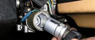
- Egnition lock. Serves to supply power to the low-voltage circuit.
In the extreme left position (clockwise), the contacts on the starter solenoid relay are closed, and the engine is driven by the starter. - Breaker. In GAZ 53 it is located in the distributor. In contact ignition, the role of the breaker was performed by the cam shaft of the distributor and the ignition contacts; in a more modern version, the role of the breaker is performed by the Hall sensor.
- Switch. Ensures stable operation of the breaker.
- Variator (resistance). Provides stable engine starting and relieves the work of the ignition coil at high engine speeds. Due to the variator, the coil does not overheat. On more modern versions of the system, the variator was removed (in the gas 3307 model), and the role of the variator began to be played by an additional transistor located in the circuit of the new switch.
- Primary winding of the ignition coil (SC). It has a small number of turns and relatively thick copper wire.
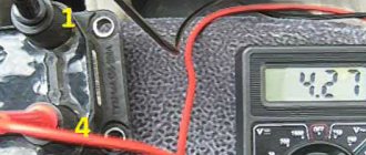
Checking the ignition coil with a multimeter
The secondary (high-voltage) circuit contains the following elements:
- Secondary winding short circuit. It has a large number of turns and thin copper wire.
- Ignition distributor GAZ 53. The distribution part of the distributor consists of a shaft, a distributor cap and a slider.
- High voltage wires and lugs. Through them, a high-voltage pulse is supplied to the spark plugs.
- Spark plug.