Published: 10/20/2020
- Repair
- Methods for checking the ignition module of a VAZ 2114
- Repair
- How to disassemble the ignition module of a VAZ 2110
- Ignition module repair
- Version of the module on the 8-valve VAZ-2112
- We disassemble the design of the ignition module of a modern injector
- Checking module power
- Possible reasons for failure of the ignition module
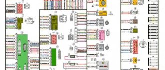
- Diagram of the correct connection of wires to the ignition module
- Connection diagram
- VAZ 2115 ignition module, description and malfunctions
Ignition coil VAZ 2114 8 valves, VAZ 2113, VAZ 2115
Here we consider the ignition coil of VAZ 2114 8 valves, VAZ 2113, VAZ 2115 model 2111-3705010-02 (54.37005) with injection engine 11183 (l,6i). The ignition coil of the VAZ 2114 injection 8 valve engine is described. The diagram of the ignition coil for VAZ 2114, 2113, 2115 is shown. The electrical diagram for connecting the ignition coil for VAZ 2114 injector 8 . Malfunctions of the ignition coil of the VAZ 2114 8 valves are given. Shown is the pinout of the ignition coil for VAZ 2114 injector 8, VAZ 2113, VAZ 2115
| Content: | |
| 1 | Description and purpose of the ignition coil VAZ 2114 8 valves; |
| 2 | The principle of operation of the ignition coil VAZ 2114 injector 8 valves, VAZ 2113, VAZ 2115 model 2111-3705010-02; |
| 3 | Explanation of the ignition coil designation (Catalogue number) - 2111-3705010; |
| 4 | Electrical diagram of the ignition coil VAZ 2114 injector 8 valves; |
| 5 | Where is the ignition coil of VAZ 2114 8 valves, VAZ 2113, VAZ 2115; |
| 6 | Analogues of the ignition coil VAZ 2114 injector 8 valves, VAZ 2113, VAZ 2115 type 2111-3705010-02; |
| 7 | Pinout of the ignition coil for VAZ 2114 model 2111-3705010-02 (54.37005); |
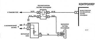
| 8 | Schematic diagram of engine control with an ignition coil VAZ 2114 injector 8 valves; |
| 9 | Electrical circuit diagram for controlling the propulsion system of model 11183 (l,6i).with ignition coil of brand 2111-3705010-02 (54.37005): |
| 10 | Signs of a malfunctioning ignition coil VAZ 2114 8 valves, 2113, 2115; |
| 11 | Checking the ignition reel of a VAZ 2114 injector 8 valves; |
| 12 | Replacing the ignition coil on VAZ 2114, 2113, 2115 cars; |
| 13 | Literature on passenger cars VAZ 2114, 2113, 2115 models and their modifications. |
Description and purpose
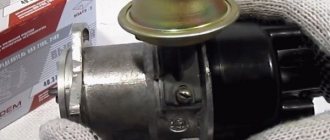
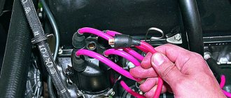
Ignition coil VAZ 2114 8 valves, VAZ 2113, VAZ 2115 are two two-output ignition reels mounted in a single casing. It is designed to convert low on-board voltage (12 volts) into high sparking voltage. Sparking occurs in two pots at once (1-4 and 2-3). The ignition solenoid is connected to the spark plugs by high-voltage wires with permanent tips.
Below, in the figure, the design of the ignition coil of the VAZ 2114 8 valves is presented
Communities › VAZ: Repair and Modification › Forum › VAZ 2110, injector, 8 cells, won’t start, no spark
Good day to all. Yesterday my friend’s car stopped starting; as it turned out, there was no spark at the spark plugs. A new Ignition Module, new explosive wires, and a new DPKV were purchased at the store. ECU January 5,1,1 was replaced with exactly the same one that was known to work. But the engine still doesn't want to work. So far I have found out that on the chip going from the ECU to the Ignition Module, on the last contact (D) there is 12 volts when the ignition is turned on, and on the penultimate one there is ground. So, as I understand, the control signals for sparking go through the 1st and 2nd connectors (A and B). But how can you find out whether these signals are reaching the coil? I connected a low-power 5w light bulb to these connectors, that is, one end to the ground of the car, and put the other end into connectors A and B and turned the starter, the light did not light up. Maybe a very weak current is generated there? Or do you need to dig in the direction of the break in both wires (which is unlikely)?
The principle of operation of the ignition coil VAZ 2114 8 valves, model 2111-3705010-02
The current in the primary windings of the ignition coils is controlled by a controller that uses information about the engine operating mode received from the engine control system sensors. To switch the primary windings of the ignition coils, the controller uses two powerful transistor valves.
From the ignition coil of the VAZ 2114 8 valves, a high voltage pulse is supplied to two cylinders at once: 1 - 4, 2 - 3. In one cylinder the compression stroke ends (working spark), and in the second the exhaust stroke (idle spark) occurs.
Due to the constant direction of current in the primary and secondary windings, the sparking current of one spark plug always flows from the central electrode to the side electrode, and the second - from the side to the central one.
The ignition coil of the VAZ 2114 injector 8 valves works according to the following principle. The vehicle's electrical system voltage is supplied from the ignition switch to contact “15” of the ignition coil. Next, the controller switches the pulse to terminal “1b”, the circuit of the primary winding of the ignition coil, as a result of which the secondary winding outputs high voltage to the spark plugs of cylinders 1 and 4. And the controller switches the pulse to terminal “1a”, the circuit of the primary winding of the ignition coil, as a result which causes the secondary winding to output high voltage to the spark plugs of cylinders 2 and 3.
Possible reasons for failure of the ignition module
Before repairing the main part in, you need to understand the nature of the problem. To do this, the consumer must be aware of the signs of a malfunction, as well as the causes of the breakdown.
The main reasons for device failure
Causes of problems:
- The ignition system uses spark plugs that do not match the vehicle parameters. They may not have the gap specified by the manufacturer. Also, the spark plugs themselves may not be working or dirty; this can be determined by visual diagnostics. If there are traces of carbon deposits on the devices, they must be removed.
- Malfunctions in the operation of the MH can arise as a result of frequent spark checks. At the time of diagnosis, a high load is placed on the device. If it appears frequently, it will lead to equipment failure or incorrect operation.
- in the VAZ 2114 it functions with the high-voltage cables disconnected. This also leads to device failure. The products themselves may be damaged, which affects the functioning of the engine as a whole.
- The device operates under severe vibration conditions. Their impact may be due to poor quality fixation of the module in the seat. As a result of vibrations, the factory soldering inside the equipment structure is damaged. This leads to its incorrect operation.
- The contact inside the plug with the low-voltage cables is broken.
- Initial use of a defective device or module with poor build quality. This factory defect can only be eliminated by replacing the mechanism; repairing the equipment is pointless.
- Moisture getting inside the case. This problem is unlikely, but exposure of the device to liquid may cause it to short out and break.
Signs of coil malfunction
The main symptoms of a malfunction in the VAZ 2114 ignition module:
- Difficulties arise when trying to start the engine. Starting the car engine may be difficult due to the fact that there is no spark on a spark plug or several.
- When idling or parking with the internal combustion engine running, the speed of the power unit floats. Their change is not associated with pressing the gas pedal and other third-party factors. This happens randomly.
- There are dips in the power of the car's engine. This is especially felt when driving uphill or sharp acceleration. Problems can also occur when driving on a flat road.
- Several cylinders stopped working. Usually these devices operate in pairs, so elements 1-4 or 2-3 could fail. Non-working cylinders may be indicated by “triple movement” of the engine.
- A “Check Engine” warning light appeared on the dashboard.
If the ignition module malfunctions, problems will appear not only in engine operation, but also when starting it.
The “Simple Opinion” channel, using the Lada Priora car as an example, spoke in detail about the symptoms that appear in the operation of the ignition modules.
Explanation of the ignition coil designation (Catalogue number) - 2111-3705010;
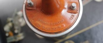
The designation of a part or assembly is a unique number in a single form. Assigned to only one part. The numbering of designations for assembly units and parts is carried out according to a unified seven-digit system. Designation - 2111-3705010-02 is deciphered as follows. The first four digits before the dash indicate the model of the base car or engine, chassis, body. In our case: 2111 is the engine model. The first two digits after the dash indicate the group number, in this case 37 - electrical equipment. The next two digits are the subgroup number. In our case, 05 is the ignition coil. The last three digits of the seven-digit number indicate the serial number of the part. The last two digits after the second dash indicate the interchangeability of the part. ХХХХ-ХХХХХХ-00 (to-09) - interchangeable. ХХХХ-ХХХХХХХ-10 (up to 19) are interchangeable with each other but not interchangeable with ХХХХ-ХХХХХХХ-00 (up to-09) and so on.
Designation
The ignition module for VAZ 2114, 2115 has the factory designation: 042.3705. According to the documentation of AvtoVAZ OJSC, it has the designation: 2112-3705010-03.
Decoding the designation of the ignition module VAZ 2114, 2115
The catalog number of the ignition module 2112-3705010-01, 2112-3705010-02 is almost identical to the catalog number of the ignition coil. The exception is the base engine. In this case it is model 2112..
The catalog (identification) number of the device or assembled unit is a single digital number. It is assigned exclusively to one part. The designation of assembly units and devices is carried out according to a unified seven-digit system. Consider the identification number of the ignition module model 2112-3705010-01
- The initial numbers before the dash indicate the model of the base car or engine, chassis, body. In our version: 2111 is the engine brand.
- 2 digits immediately after the hyphen indicate the group number, in our case 37 is electrical equipment;
- The next 2 digits indicate the subgroup number. In our version 05 is the ignition module;
- The last three digits in a seven-digit number indicate the serial number of the device;
- The very last 2 digits after the second hyphen indicate the interchangeability of this part. Numbers ХХХХ-ХХХХХХ-00 (up to-09) are interchangeable. Numbers of the type ХХХХ-ХХХХХХХ-10 (up to 19) are interchangeable with each other but not interchangeable with the number ХХХХ-ХХХХХХХ-00 (up to-09) and so on.
The device identification number is applied to the part body. It helps resolve the issue of interchangeability and suitability of a given part when purchasing and searching for it.
Pinout, connection diagram and check of the VAZ ignition coil
Today we will look at the design and diagrams of ignition systems for VAZ cars of all major models. Since carburetor versions of VAZ are practically history, we will dwell in detail on the ignition systems of injection cars. Their ignition system is based on an electronic ignition module. We also recommend that you carefully consider the choice of spark plugs and the quality of high-voltage wires, because the quality of the spark and, accordingly, the operation of the ignition system as a whole will depend on them. The information is intended as a reference guide for self-repairing a car.
For what malfunctions is it possible to repair the device?
Due to the fact that the ignition module by design includes a connection of two coils, it is difficult to repair. If there is a break or breakdown, as well as melting of the turns, the problem can be solved by replacing the device. This applies to any damage that appears inside the coils. The only option to correct the situation without replacing the device is to repair the damage to the solder joint.
Ignition module repair process
The repair procedure is carried out after preparing all tools and materials:
- a set of socket wrenches, you will need a tool for 10, 13 and 17;
- hexagon 5;
- flat head screwdriver;
- soldering iron with aluminum and flux;
- nail polish;
- multi-core conductors.
Restoring the ignition module operation is done as follows:
- The key is installed in the switch. The engine starts. Then you need to move the contact elements on the module to make sure they are not working.
- The power unit stops. The module is being removed.
- The device body is cleaned from dust. To disassemble, you need to open the case; this is done by prying it off with a screwdriver. Inside the device there is a board on which there is a silicone film; you need to get rid of it.
- Aluminum is removed from high-voltage contact elements. Old wires are removed.
- The next step will be soldering new conductors to the circuit. To do this, the surface of the collector device is cleaned from traces of plaque. Then the board must be installed on an electric stove and heated to approximately 200 degrees. As the temperature increases, a slight burning smell may be heard. This is not a problem for the circuit; heating it will simplify the soldering procedure.
- Then soldering is done. Using a soldering iron, flux and aluminum, the ends of the conductors must be connected to the ignition module. All contact elements of the conductors that are connected to the circuit must be treated with nail polish.
- Then the device is assembled in the reverse order and installed in the seat. After installation, the power unit starts up. If the repair solves the problem, then using a sealant, the device is fixed in place.
- If a transistor or switching device fails, then these components cannot be repaired, but they can be replaced. To do this, the parts are removed from the board and replaced with new ones.
Ilya Balashov presented a video with the result of soldering the ignition module using the example of a VAZ 2110 car.
Pinout and diagram of the VAZ ignition coil
Pinout of ignition coil modules for various car models of the VAZ family:
Ignition VAZ 2101
1 – generator; 2 – ignition switch; 3 – ignition distributor; 4 – breaker cam; 5 – spark plugs; 6 – ignition coil; 7 – battery.
Ignition VAZ 2106
1 – ignition switch; 2 – fuse and relay block; 3 – EPHH control unit; 4 – generator; 5 – solenoid valve; 6 – microswitch; 7 – spark plugs; 8 – ignition distributor; 9 – ignition coil; 10 – battery.
Ignition VAZ 2108, 2109
Ignition VAZ 2110
Ignition VAZ 2111
Ignition VAZ 2112
Ignition VAZ 2114
Diagram of a non-contact ignition system: 1 – non-contact sensor; 2 – ignition distributor sensor; 3 – spark plugs; 4 – switch; 5 – ignition coil; 6 – mounting block; 7 – ignition relay; 8 – ignition switch.
PREVENTION OF THE SYSTEM
Despite the high reliability of electronic devices, breakdowns still occur. Sometimes they can be avoided if you carry out at least occasional inspection and maintenance of the elements of this system:
- Avoid confusion with high voltage wires; if their internal resistance increases greatly, this can damage the coils;
- Check the gap between the electrodes of the spark plugs, since too large a spark gap also negatively affects the device.
[custom_ads_shortcode3]
How to check the ignition coil of a VAZ
If the ignition coil is faulty, the engine will not start. A characteristic sign of a faulty coil is its increased temperature when the ignition is turned off. This is easy to determine by touch.
Signs of a faulty ignition module may include the following:
- hesitant engine starting or failure to start;
- failures during sudden changes in speed;
- high fuel consumption;
- two cylinders do not work, the engine is feverish;
- lack of dynamics;
- a sharp drop in power;
- drop in power and thrust after warming up.
These symptoms may not only be caused by the ignition module. To determine the malfunction, it is enough to spend a few minutes diagnosing spark plugs, high-voltage wires and caps. This will eliminate the remaining elements of the ignition system and make sure that it is the ignition module that is faulty.
Checking the ignition coil is performed in one of 2 ways. The simplest one is to remove the central wire from the breaker-distributor, bring it to the motor housing and turn it with the starter, and a running spark should appear. After this, we check the energy supply to a separate spark plug, for which we unscrew the working spark plug, bring its contact to ground and attempt to start the engine. In this case, the spark should come from the wire to ground. If it is absent, the reason will be a malfunction of a system element such as the ignition coil.
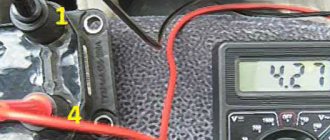
To check the module in the second way, we only need a multimeter, then follow the step-by-step instructions:
- We check the power supply and the presence of pulses supplied from the ECU. We check the power between the central terminal (15) of the wire block connected to the module and the engine ground. When the ignition is on, the voltage should not be less than 12 V. Otherwise, either the battery is dead or the ECU does not work.
- We check the pulses from the ECU on the wiring block. We install one tester probe on connector 15, the second on the far right, then on the far left. The assistant cranks the engine with the starter, and at this time we record short-term voltage surges with a tester. If there are no impulses from the ECU, it is he who is to blame.
- We check the resistance on the secondary windings of the coils. We put the tester in resistance measurement mode and measure it at the high-voltage terminals of the module cover. Between pins 1 and 4 and pins 2-3, the resistance should be 5.4 kOhm. Otherwise, the module must be replaced.
- We check the resistance of the primary windings between contacts 15 and the rightmost, then the leftmost terminals. Nominal - 0.5 Ohm. Deviation is not allowed.
- Check the module for a short circuit. In ohmmeter mode, install one multimeter probe on the central terminal, the second on the metal body. There shouldn't be any resistance. If the device detects at least some resistance (other than unity or infinity), the module must be replaced.
Ignition module repair
If the ignition module does not work, you can try to rehabilitate it:
- Take 10, 13 and 17 end keys, a 5 hex key, a regular screwdriver, a soldering iron, aluminum flux, nail polish, and stranded wires.
- Most often, the connection in the ignition system deteriorates - those same contacts.
- We turn the key in the ignition, start it, move the contacts, and get a comprehensive answer in the absence of their quality connection.
- Now we turn off the engine and remove the ignition module out.
- You need to open it, pry up its body with a screwdriver.
- Inside the board is covered with silicone film - remove it.
- We remove all aluminum from the explosive contacts.
- Now comes the hard part: we need to solder new wires to the plan from where we just removed the old ones.
- First, you need to clean the surface of the collector from plaque, then put the board on the stove and heat it to 200 degrees (approximately by eye, of course), it will start to smell a little when it reaches the desired temperature and soldering on it will become much easier.
- Now, actually, we solder: we connect the ends of the wires to the module.
- We cover all the contacts of the wires with the module and the board with nail polish.
- Now you need to put everything back together, put the ignition device in place and start the engine. Only after this, when you are convinced that everything is working properly, can you take the sealant and seal it tightly.
- Individual elements that have failed. They cannot be repaired, they are only for replacement. Fortunately, the price for them is adequate: a switch is within 200 rubles, a transistor is from 200 to 300 rubles.
A very important point: in common parlance, as here, the ignition coil and the ignition module are synonyms. But in terms of technical design, no. For fourteenths with different engine sizes, different spare parts are installed: for 1.5-liter Samaras of the old generation, it is the ignition module, and for 1.5 and 1.6 liters of the new generation Samaras, it is the ignition coil. The switch of the new type of machines is hidden in the electronic control unit, it turns out that the module was broken, and they began to call it by the name of its main part - the coil. Be careful when choosing a spare. parts from disassembly: do not confuse them, given this fact.
If we talk about service, the price is not worth the cost. It’s easier to figure everything out yourself, even more so. That there are a lot of resources where they can give you advice and help. The main thing is to remember the layout of the high-voltage wires and their good contact. It happens that incorrectly connected wires contribute to improper combustion, a spark hits the relay. And the ignition module completely burns out.
Connecting and replacing VAZ short circuit
The procedure for removing and installing the ignition coil on old VAZ models:
- First, disconnect the central high-voltage wire leading to the distributor (ignition distributor).
- Disconnect all power wires from the coil contacts. Since they are fastened with nuts, you will need an 8 wrench for this.
- If you don’t know which wires to connect to which connector later, it’s better to immediately remember or mark them somehow, so that later during installation you can connect them correctly.
- Unscrew the coil housing. It is attached to a clamp (clamp), which is pressed to the car body with two nuts.
- After the work has been done, you can remove the ignition coil and replace it if necessary.
For new type VAZ cars:
- We remove the “minus terminal” from the battery.
- Remove the top protective cover of the engine. If the engine volume is 1.5 liters, then this part is missing and this step is skipped.
- We remove the high-voltage wires from the coil.
- Now, using a 13mm wrench, unscrew the two fasteners.
- Using a 17mm wrench, loosen one bolt securing the coil.
- We take out the module.
- Use a hexagon to unscrew the coil from the holder.
- Assembly is carried out in reverse order.
Particular attention should be paid to the connection, since high-voltage wires must be located in the strict order provided for by the design. If this is not done, the car will stall or the engine may not start at all.
Replacing the ignition coil on a VAZ is quite simple. Even a novice motorist can do this in his garage, and if everything seems too complicated, contact a car service center. Particular attention should be paid to the choice of product, since this will determine how well the engine and ignition system will work.
What's the difference between contactors and starters?
Both contactors and starters are designed to close/open contacts in electrical circuits, usually power ones. Both devices are assembled on the basis of an electromagnet and can operate in DC and AC circuits of different powers - from 10 V to 440 V DC and up to 600 V AC. Have:
- a certain number of working (power) contacts through which voltage is supplied to the connected load;
- a number of auxiliary contacts - for organizing signal circuits.
So what's the difference? What is the difference between contactors and starters? First of all, they differ in the degree of protection. Contactors have powerful arc extinguishing chambers. This leads to two other differences: due to the presence of arc arresters, contactors are large in size and weight, and are also used in circuits with high currents. For low currents - up to 10 A - only starters are produced. By the way, they are not produced for high currents.
There is one more design feature: the starters are produced in a plastic case, with only the contact pads exposed outside. Contactors, in most cases, do not have a housing, therefore they must be installed in protective housings or boxes that will protect against accidental contact with live parts, as well as from rain and dust.
In addition, there is some difference in purpose. The starters are designed to start asynchronous three-phase motors. Therefore, they have three pairs of power contacts - for connecting three phases, and one auxiliary one, through which power continues to flow to operate the engine after the “start” button is released. But since a similar operating algorithm is suitable for many devices, a wide variety of devices are connected through them - lighting circuits, various devices and devices.
VAZ models 8 and 16 valves
Despite the similarity in engine design, the ignition system of the 1.5-liter injection 16-valve engine differs from the 1.6 16-valve engine. The 1.6 liter engine uses an electronic contactless ignition system with individual coils on each spark plug. Therefore, there was no need for an ignition module. Such a system is more reliable and cheaper to operate, since if one coil fails, there is no need to replace the entire module.
The 16-valve 1.5-liter VAZ 2112 injection engine used the same non-contact ignition system as the 8-valve engine, but a different ignition module was installed. Its catalog number is 2112-3705010. The design of the module remains the same - two ignition coils (for cylinders 1-4 and 2-3) plus switch keys in a single block. The spark is supplied to the cylinders in pairs using the idle spark method. This means that sparking occurs in two cylinders simultaneously - in one on the compression stroke (working spark), in the second on the exhaust stroke (idle spark).
We disassemble the design of the ignition module of a modern injector
As an example, consider a similar device used on injection VAZ cars. The module operates according to the good old principle: 12 volt power is supplied to the input, and a high voltage is generated at the output contacts for sparking.
The control is electronic, but the operating principles differ from a simple distributorless ignition system:
- All components are located in one housing. On the one hand, this is convenient - fewer wires and contacts - lower probability of breakdown. On the other hand, if the ignition module burns out, it must be repaired; simply replacing the failed element will not work.
- The device is compact and can be conveniently placed in the engine compartment.
- The ignition module is powered at low voltage, which increases the reliability of the device.
- The cost of the finished device is low.
- This ignition module has two coils. This contributes to the survivability of the device - each transformer is loaded twice as much.
The secret of the module’s operation is as follows: it uses not four, but two coils for 4 cylinders. Masters of the old school call this device a two-spark bobbin. Alternating connection of each coil produces two sparks: working and idle. Due to proper distribution among the spark plugs, the idle spark is ignited at the moment when there is no air-fuel mixture in the corresponding cylinder.
The signal for sparking is given by the switch (acting as an electronic distributor). Before checking the ignition module, you need to make sure that control pulses are coming to the contact blocks from the switch.
This block is responsible for the so-called ignition advance, that is, it generates a signal at the right moment. The control pulse about the position of the crankshaft is issued by the Hall sensor, which also synchronizes the operation of the entire system.
Video on repairing KZ VAZ
Source
| 1 | accumulator battery; |
| 2 | main relay; |
| 3 | ignition switch; |
| 4 | spark plug; |
| 5 | ignition coil VAZ 2114 8 valves model 54.37005; |
| 6 | controller; |
| 7 | crankshaft position sensor; |
| 8 | master disk. |
| 1 | ignition switch; |
| 2 | main relay; |
| 3 | battery; |
| 4 | atmospheric filter; |
| 5 | diagnostic connector; |
| 6 | dashboard; |
| 7 | tachometer; |
| 8 | check lamp; |
| 9 | speedometer; |
| 10 | immobilizer sensor with indicator; |
| 11 | immobilizer manual device; |
| 12 | electric fan of the engine cooling structure; |
| 13 | electric fan relay; |
| 14 | controller; |
| 15 | DTOZH; |
| 16 | ignition coil VAZ 2114 8 valves, VAZ 2113, VAZ 2115; |
| 17 | spark plug; |
| 18 | DPRV; |
| 19 | sprayers; |
| 20 | throttle assembly; |
| 21 | TPDZ; |
| 22 | DMRV; |
| 23 | empty control; |
| 24 | Lambda probe; |
| 25 | car speed sensor; |
| 26 | DPKV; |
| 27 | DD; |
| 28 | crankshaft pulley; |
| 29 | gasoline filter; |
| 30 | petrol pump relay; |
| 31 | gasoline tank; |
| 31 | gasoline unit; |
| 32 | two-way valve; |
| 33 | gravity throttle; |
| 34 | reverse breather; |
| 35 | check valve; |
| 36 | adsorber purge throttle; |
| 37 | adsorber; |
| 38 | separator. |
| 1 | spark plug 4 pots; |
| 2 | spark plug 3 cylinders; |
| 3 | spark plug 2 pots; |
| 4 | spark plug cylinder 1; |
| 5 | ignition coil VAZ 2114 8 valves; |
| 6 | diagnostic connector; |
| 7 | 1 pot sprayer; |
| 8 | injector 2 cylinders; |
| 9 | 3 pot sprinkler; |
| 10 | 4 cylinder injector; |
| 11 | ECU; |
| 12 | fuel pump switch; |
| 13 | to the electric cooling radiator fan; |
| 14 | connector for connecting the engine radiator electric fan; |
| 15 | main relay for engine control mode; |
| 16 | DMRV; |
| 17 | remote sensing; |
| 18 | DTOZH; |
| 19 | empty traffic controller; |
| 20 | adsorber purge throttle; |
| 21 | DPKV; |
| 22 | DD; |
| 23 | oxygen concentration sensor; |
| 24 | to the ignition switch; |
| 25 | Immobilizer ECU; |
| 26 | immobilizer sensor with signaling device; |
| 27 | car speed sensor; |
| 28 | spare pad; |
| 29 | to the battery positive; |
| 30 | DPRV; |
| 31 | block for connecting to the car's electrical network; |
| 32 | fuel unit; |
| F1 | fuse for the ECU and engine control structure circuits; |
| F2 | ECU fuse; |
| F3 | fuel pump line fuse |