When designing the small car VAZ Oka 1111 and 11113, many components and mechanisms were “borrowed” from other VAZ models, which made it possible to reduce the cost of car production and speed up the start of production. But the designers had to significantly rework some components in order to adapt them to the features of the Oka engine. One of these components is the ignition system.
When creating the ignition system, the designers used modern developments of those years. The VAZ Oka received a non-contact ignition system. At the same time, the features of the power plant made it possible to somewhat simplify the system and reduce the number of components, which had a positive impact on the reliability of this component of the power plant.
The switch is. Switch diagram. How to check the ignition switch
The switch is an electronic component to ensure the operation of a contactless ignition system. It is transitional between contact and microprocessor. The latter, the most advanced, allows you to control the torque using data read from sensors - oxygen, speed, engine speed and others. But there are still many cars on the roads that have both contact breakers and contactless ones. Therefore, for maintenance and diagnostics, you need to know the purpose of all elements, as well as troubleshooting methods and their main symptoms. Before testing the switch, review all parts carefully.
Fuse box diagnostics (video)
VAZ-1111 especially small class passenger cars are equipped with 12-volt electrics with a negative terminal connected to the car body. The cars were equipped with carburetor and injection power units, which had little effect on the location and purpose of the circuits. The VAZ-1111 electrical circuit, which is basic for all versions of the Oka, can be used when repairing a car of any year of assembly.
What is included in the Oka electrical circuit?
Electrical diagram of VAZ-1111 with symbols
Electrical diagram of VAZ-11113 with symbols
Contactless ignition diagram indicating the main elements and connecting wires
Fuse diagram for VAZ-1111 and 11113
Common electrical faults
Contactless ignition system
In total, there are three huge groups of systems - contact, contactless, microprocessor. The first is divided into two subgroups - contact and using a transistor operating in switch mode. Transistors are also used in the design of a contactless ignition system. This scheme began to be actively used in the early 80s of the last century. And it has a number of advantages, which will be discussed below. The switch circuit is simple; it can be implemented both on transistors and on a controller.
But the contactless ignition system also has many disadvantages when compared with a microprocessor one. The latter allows you to control almost all engine parameters. BSZ does not allow this; it also cannot be used normally on injection engines. The reason for the obsolescence of the contactless system lies not only in the development of electronics and the automotive industry, but also in the adoption of stringent measures to ensure the environmental friendliness of internal combustion engines. Unfortunately, only microprocessor control can reduce the amount of harmful substances in the exhaust.
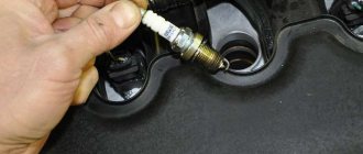
Video “Instructions for replacing the ignition coil”
Learn more about how to replace the ignition coil in Oka with your own hands from the video below (author - Butovsky Gulyak channel).
As you know, Oka cars are equipped with a rather imperfect 2-spark ignition system (similar to the options installed on some motorcycles). In general, the use of such a principle of organizing the ignition system cannot be called particularly flawed, however, due to the design features and the not very high quality of individual elements, it has a number of significant disadvantages. In particular, Oka owners are well aware of the existence of problems with starting these cars in winter (even a slightly “supercharged” battery simply cannot cope with maintaining a “push-pull” spark). The state of insulation between the high-voltage and low-voltage circuits of standard double-spark coils does not stand up to criticism either, as a result of which they very quickly fail due to moisture ingress and in damp weather. And, finally, such an unpleasant phenomenon as occasional “shots” in the muffler is also a consequence of the use of a two-spark ignition system - when an incompletely burned mixture is squeezed out by a piston into the intake manifold and, with the valves open, is ignited there by a “non-working” spark.
Be that as it may, the need to modernize the ignition system of the VAZ-1111 Oka is beyond doubt, and currently three main methods are most widespread:
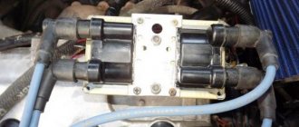
- Introduction into the system of a standard VAZ 2108 distributor with high-voltage ignition distribution, one ignition coil and one switch (from the same place). In this case, two of the four curtains in the spark moment sensor are cut off, or unnecessary spark plugs are fixed in a neutral place in the engine compartment (it is prohibited to leave excess high-voltage wires without discharge).
- Installation of a combined two-spark unit in an imported or domestic version of the “all-in-one” type (switch + coil);
- Installation of the coils of two oil-filled ignition coils from the VAZ 2108, as well as two switches with the combination of their inputs to the output of the torque sensor.
Main elements of the system
Of course, the first thing to mention is the spark plugs. They are installed in the cylinder head, the electrodes come out from the inside. These are the elements that allow the air-fuel mixture to ignite. But with the help of spark plugs alone, the engine will not be able to run. It is necessary to monitor the position of the crankshaft in order to know in what position the pistons are in the cylinders.
For this purpose, an inductive sensor operating on the Hall effect is used. It is part of the design of another element - the ignition distributor. The sensor produces a pulse that is sent to the switch. This device allows you to amplify a weak signal to a voltage of 12 volts, and then apply it to a coil. A coil is nothing more than a simple transformer (step-up). Its secondary winding has a greater number of turns than the primary. Due to this, the voltage increases and the current decreases. The voltage in the BSZ is supplied to the spark plugs at a value of 30-35 kV (depending on the car model).
Models, design and characteristics of VAZ switches
Electronic switches used on VAZ cars are divided into two large groups:
- Transistor;
- Based on specialized microcircuits.
The device of a modern VAZ switch
Typical connection diagram for an electronic switch
The simplest design is for transistor switches, which were historically the first (they replaced contact-transistor devices that were widely used on VAZ Classic cars). In essence, this is an electronic key, complemented by a signal amplifier from the pulse sensor, as well as protection and temperature compensation elements. The key is built on one powerful transistor, which is controlled by one or two transistors that amplify and change the signal from the Hall sensor. Zener diodes included in the circuit (prevent voltage surges), thyristors (disabling the switch or its individual elements in emergency modes) and other parts can act as protection elements. And temperature compensation elements (chains of resistors and capacitors) ensure constant operating modes of semiconductor devices over the entire permissible temperature range.
The operation of a transistor switch is quite simple. While there is no signal from the Hall sensor, the electronic key is open and a direct current flows through the primary winding of the coil - at the moment there is no current in the secondary winding. When a signal is received from the sensor, the switch closes, interrupting the current in the primary winding. Due to the presence of inductance, the current in the primary winding does not drop to zero instantly, but over a certain period (fractions of a second), the phenomenon of electromagnetic induction occurs - as a result of this effect, high-voltage alternating current also appears in the secondary winding. This current flows through the distributor to the spark plug, where sparking and ignition of the combustible mixture occurs. At a subsequent moment, a direct current again flows through the primary winding, so the current disappears again in the secondary winding. Then the described processes are repeated again up to 200-300 times per second.
Transistor circuitry is incorporated into the switch model 76.3734. This device is simple and reliable, but it has a number of disadvantages. For example, as the crankshaft rotation speed increases, the current in the secondary winding decreases significantly; the switch also has limited functionality and cannot ensure efficient operation of the ignition system in all modes.
Electronic switches based on specialized microcircuits do not have these disadvantages. This switch also uses an electronic key on a powerful transistor, but the key control is assigned to a microcircuit, which significantly expands the functions and capabilities of the entire device. In particular, switches with microcircuits implement functions for regulating the time of energy accumulation in the coil, spark-free cutoff (limiting spark formation when the ignition is on but the engine is stopped), various levels of protection, and others. Thanks to the ability to regulate the energy storage time, switches on microcircuits provide stable sparking throughout the entire crankshaft speed range, which is why they are so widespread.
How is BSZ better than contact?
Having carefully read the previous section, you can see that the system uses an inductive non-contact Hall sensor. The advantage is obvious - there is no friction and commutation. For comparison, look at the contact system. In it, the breaker switches the voltage, the value of which is 12 Volts. Whatever one may say, the metal contacts are constantly in contact with each other, gradually wear out, and become covered with soot.
For these reasons, it is necessary to constantly monitor the breaker, adjust the gap, and carry out timely replacement. BSZ is devoid of these shortcomings, therefore, without third-party intervention, the system operates much longer. The Hall sensor fails very rarely, as does the switch. This increases the reliability of the system, but precautions must also be taken, in particular, the connection of the switch to the body must be as tight as possible to ensure effective heat exchange. In addition, BSZ allows you to improve engine performance, increase, albeit slightly, its power, along with increasing reliability.
How to identify a blown fuse
It is quite simple to assess the condition of cylindrical type modules, as well as knife type ones. In both cases, a melting element is laid in the center of the fuse.
As soon as the current exceeds the permissible value, the plate instantly melts, opening the contacts. A small black spot forms, which is evidence that the part is faulty.
The module is removed from its seat using special plastic tweezers. In life, an accessory is often lost, so it is practiced with your fingers. After replacement, we put the power terminals on the battery, start the engine, and test the system.
How does a switch work?
Essentially, a switch is a simple signal amplifier. It can even be compared to a Darlington assembly, which is used in microcontroller technology to convert a weak signal from an output port to the required level. The basis of this assembly is field-effect transistors operating in switch mode. An operating voltage is applied to them, a signal is sent to the control terminal, which is amplified and removed from the collector.
The ignition switch has an almost similar operating scheme. Only the signal from the Hall sensor is used. It has three outputs - control, common, plus power. When a metal plate appears in the sensor area, a current is generated, which is supplied to the input of the switch. Next, the signal is amplified and supplied to the primary winding of the coil. The entire system is powered only after the ignition is turned on (after turning the key).
Basic Switch Elements
The switch circuit is quite simple, but making this unit yourself is pointless, since buying a ready-made version will be much easier. Installation must be carried out as competently as possible, otherwise the device will not operate correctly. In addition, when using transistors, you need to carefully select them according to their parameters, and for this you need to have high-quality measuring equipment. Unfortunately, for two identical semiconductors, the spread of characteristics can be very large. And this affects the operation of the device.
Maintenance
The declared resource of Oka engines under conditions of timely and correct maintenance is 120 thousand km. That is, these units, despite a number of inherent problems, can be called relatively reliable in their category.
The scheduled maintenance period is every 15 thousand kilometers. As part of the service, the oil is changed (it is advisable to use a synthetic lubricant; if semi-synthetics were poured into the engine, the interval is reduced to 10 thousand km). Therefore, when choosing which oil to pour into the Oka engine and when, you should clarify what liquid is already in the crankcase. When replacing, the oil system is washed and the oil filter is changed. Oil viscosity grade – 0W 40. 5W 40, 10W 40, depending on the season.
Valve clearance adjustment is supposed to be done every 30 thousand, but in fact it is carried out according to necessity and the actual condition of the engine. Also at this mileage you should clean the carburetor and adjust the idle speed.
After 60 thousand mileage, the fluid in the cooling circuit should be changed. If this is not done on time, the substance will degrade and lose its anti-corrosion and lubricating properties, reducing the life of the system as a whole. At this mileage, it is strictly necessary to replace a worn timing belt: if it breaks, the valves will bend, which will lead to the need to change the engine or make expensive repairs.
Connecting the switch
Cases vary, and it is possible that you will have to change the wiring. Therefore, you will need to take into account the purpose of all pins on the switch plug. This will allow the connection to be made correctly, and there will be no risk of damaging it. The first pin of the switch is the output. In other words, the amplified signal is removed from it. It must be connected to the terminal of the “K” coil. The second contact is connected to ground - the negative of the battery.
All three wires from the Hall sensor go to the VAZ switch. Moreover, the signal wire is connected to the sixth terminal of the switch. The fifth is the power output (the voltage on it is stable 12 Volts). The third output of the switch is ground (minus power). The third is connected inside the block to the second. But between the fourth, which is supplied with power from the battery, and the fifth there is a constant resistance and a voltage stabilizer.
Common electrical faults
Common problems with electrical equipment on VAZ-1111 and 1113:
- Failure of external lighting devices. A common cause of failure is burnt out lamp filament; the unit must be replaced. If the light bulb is intact, then there may be a defect in the electrical wiring, due to which a short circuit occurs and the fuse fails. The fuse link is replaced with an identical one; it is prohibited to use parts designed for a higher current. It is also unacceptable to install homemade jumpers (“bugs”), as this can cause a fire. If a repeated burnout occurs, it is necessary to check the circuit and eliminate the wiring fault.
- Wire breaks occur at points where the insulation is subject to bending or friction against moving surfaces. An example of such a point is the junction of the door and the body. Damaged areas must be replaced with products made of similar material with an identical cross-section.
- Oxidation of contact surfaces due to moisture or aggressive liquids (for example, battery electrolyte). It is necessary to clean the surfaces down to metal, restoring the transmission of electric current.
- Relay failure associated with burnt contacts or coil breakage. The unit cannot be repaired; it must be replaced with a new one. In the event of a rapid re-failure, the vehicle's electrical system must be checked at a car service center.
- Sudden battery discharge is due to an internal short or current leakage. In winter, a partially charged battery may lose capacity due to low air temperatures. You need to charge the battery and check the condition of the wiring. If necessary, the power source must be replaced.
- Pulsating operation of external lighting lamps with an unusually bright glow indicates a breakdown of the relay regulator on the generator. Repair requires removing the unit and replacing failed components.
- Insufficient battery charge (the warning light does not go out when the engine is running). The cause may be wear on the brushes or commutator, or insufficient tension on the drive belt. The generator needs to be repaired, since the battery charge is enough for 150-200 km during the daytime.
- Poor contact between the ends of the cylindrical fuses and the spring-loaded elements in the mounting block. It arises due to the design features of the unit. Many owners, tired of dealing with the defect, install homemade blocks for knife inserts. Usually a short section from the GAZ-3110 is used, designed for 13 seats. There are self-assembled units designed for fuses and relays.
Photo gallery
The process of installing a new mounting block with blade elements.
Burnt contact of the standard unit
Destruction from local heating is clearly visible
Jumpers on the new block required to reduce the number of insertion locations
Wired unit
How to check
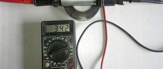
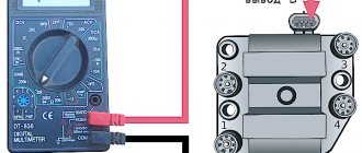
There is nothing complicated in this procedure. The easiest way is to use a known-good node, since you can check the switch this way in literally a matter of minutes. But if there is none, and you need to determine exactly whether the fault is in the coil or in the switch, it is wiser to use other methods. You will need a simple incandescent lamp. If you don’t know where to get it, then unscrew it from the interior lamp or from the side lights.
Connect one terminal of the lamp to the negative of the battery. Connect the second one to pin “1” of the switch. This is the same pin from which the amplified signal is removed. If the lamp lights up, then the device is working properly. A more advanced testing method is carried out using an oscilloscope. On the screen you can see the magnitude and shape of the signal, and also compare it with the reference one.
Add-ons
Setting the correct initial OZ
The strategy for this procedure is described on any fence; I will only indicate what is not described there.
The purpose of the procedure: by reducing to 850 rpm at idle and moving the distributor, to achieve the location of the mark (which is on the pulley in the clutch housing, it is illuminated by a strobe light) on the 2nd division.
Installation method: if the speed changes, return it to 850, changing the quantity and quality of XX with the screw, and moving the distributor, return the mark to the 2nd division. Until it becomes like this: 850 revolutions - and the mark is on the 2nd division.
Once again: 4 degrees (2 divisions) at 850 rpm for the 11113 engine.
Those who wish can, just in case, disconnect the vacuum regulator hose - it still does not work at XX.
The angle on 2108 and on Oka-1111 models (0.65 cc) is set to 1+-1.
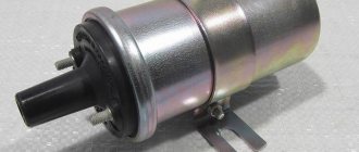
Coil installation location
For a simple test, just screw the coil to the brake cylinder mounting bolt, which is located directly under the spare wheel. If it’s a pity to spoil the wiring, then the wires from the old coil will need to be lengthened.
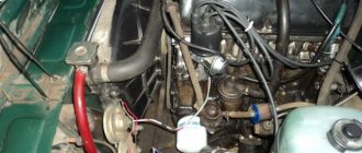
High voltage wires
They say that the wires from the Niva (namely, the central one, from the coil to the distributor - longer than the others) are more suitable and allow the coil to be placed more comfortably. So far I have installed simple ones from 2108 - and the coil is attached to the brake cylinder mounting bolt.
The new distributor does not interfere with the spare tire (still
5 cm remains to the tire). Which suggests that it was probably planned there. In what thread is a very smart design bureau.
Fuel consumption
But actually, why should consumption increase? This has not happened to me yet, thank God, immediately after installation, during a period of close observation and observation of the distributor’s operation (about 3 weeks), I found out that my consumption was around 5.5 liters per 100 km (excluding warm-up consumption ). I will describe more detailed information about how this happens in another topic, since it is also important what kind of carburetor, spark plugs, wires and switch are used on the machine. I am not able to describe everything at once, but I will definitely describe it. Stay tuned for new topics and links!
Ignition settings
When setting up the ignition, you will need to do the most important thing - install the shafts according to the marks so that the gas distribution functions synchronously with the operation of the piston group. This is the first thing you should do before you start adjusting the ignition. It is worth noting that there should not be any particular difficulties during setup, especially on VAZ 2108-21099 cars. The thing is that the ignition distributor on the engines of these machines can only be installed in one position. Moreover, the ignition switch does not undergo any settings during this procedure, since it does not have any.
The distributor body rotates around its axis to make more precise adjustments. And this turns out to be enough. To accurately set the torque, you can use a simple circuit that uses a simple LED as an indicator. The Hall sensor is disconnected from the system, and positive power is supplied to its negative terminal. An LED is switched on between “+” and the signal LED, and a 2 kOhm resistance is connected in series with it to reduce the voltage. But the plus of the Hall sensor is connected to ground. Now all that remains is to slowly rotate the distributor housing. The moment when the diode lights up will be the desired one.
Setting the advance angle
Setting the ignition timing is the only operation that is performed in the ignition system.
A strobe light is used to set the angle correctly. The technology for performing the work is not complicated. The algorithm of actions is as follows:
- We connect the strobe to the power source and the tip of the spark plug of the 1st cylinder (according to the instructions for the device);
- Remove the plug from the inspection window on the clutch housing;
- We start the engine (it should be idling);
- We direct the beam of light from the strobe into the viewing window;
- We determine the position of the marks (with the angle correctly set, the mark on the flywheel at the moment the strobe light beam flashes should be located between the central and rear marks on the crankcase);
- If the marks are not positioned correctly, make adjustments. To do this, loosen the bolts securing the spark moment sensor and rotating it around its axis until the marks match;
Related link:
Adjusting Oka valves
After adjustment, tighten the sensor fasteners, turn off the engine, disconnect the strobe light and replace the plug.
conclusions
Many advantages are provided by such a simple unit in a contactless ignition system as a switch. This includes an increase in power, even if only slightly, a reduction in fuel consumption, and a significant improvement in the engine in terms of reliability. And most importantly, there is no need for constant monitoring and timely adjustment of the system. The modern driver does not want to repair a car, he needs a means of transportation. Moreover, it is reliable and will not let you down at the most crucial moment. Regardless of which switch is used in the BSZ, its efficiency is much higher than that of a contact breaker.
Electrical diagram of VAZ-11113 with symbols
The electrical circuit of the VAZ-11113 does not differ significantly from the VAZ-1111. The car was equipped with a modernized version of the power unit and some components that had virtually no effect on the electrics.
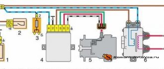
Contactless ignition diagram indicating the main elements and connecting wires
Contactless ignition VAZ-11113
- 1 - control relay;
- 2 — ignition switch with contact group;
- 3 - protective fuse;
- 4 - controller;
- 5 - sensor that determines the moment of spark supply;
- 6 - common ignition coil;
- 7 - candles.
Electrical wiring diagram for the Oka car (VAZ-1111).
How to save the diagram on your computer, see previous articles, for example here. I'm tired of writing the same thing in all my articles :).
Description and diagram of Oka:
- Front turn signal lamps
- Headlights
- Electric motor driving the cooling fan
- Audible tone
- Sensor automatically turns on the fan motor on the radiator
- Starter
- Electric windshield washer
- Generator
- Oil pressure lamp sensor
- Temperature sensor for coolant temperature indicator (antifreeze, water)
- Plug socket for portable lamp
- Electronic ignition switch
- Spark torque sensor
- Candles
- Accumulator battery
- High-voltage ignition coil for two spark plugs
- Frog switch for automatically turning on the lights in the reversing lights
- Solenoid valve located on the carburetor
- Electric windshield wiper
- Sensor for monitoring the brake fluid level in the reservoir
Wiring diagram VAZ-1111-Oka
- Fuse block panel
- Relay-breaker for the lamp for monitoring the position of the parking brake lever
- Radiator fan power relay
- Starter Bendix Voltage Relay
- Relay for supplying voltage to the rear window heating element
- Relay for supplying voltage to the spiral of the high beam lamps
- Relay for supplying voltage to the spiral of the low beam headlight lamps
- Voltage breaker relay in the direction indicator and hazard warning light circuits
- Ignition relief relay
- Ignition switch (lock)
- Individual taillight fog light circuit fuse
- Switch for different operating modes of the windshield wiper
- Button for activating the windshield washer
- Switch-button for sound signal
- Switch (lever) for switching between high and low beam headlights
- Switch (lever) direction indicators
- Brake pedal button
- Switch for rear window wiper and washer
- Fixed button that turns on the rear window defroster
- Rear fog light switch
- Indicator lamp, carburetor damper position
- Fixed hazard warning light button
- Multi-position switch for outdoor lighting devices
- Cigarette lighter socket
- Engine coolant temperature reading device
- Combined control panel
- Heater motor speed switch
- Illumination lamp from inside the instrument cluster
- Additional active resistance (resistor) in the heater motor circuit
- Indicator lamp for reserve fuel level mode
- Heating turbine electric motor
- Fuel level indicator
- Button-limit lamp for monitoring the carburetor air damper
- Side redundant turn signal repeaters
- Light switches in the cabin, located in the door pillars
- Parking brake control lamp switch
- Lamp in the cabin
- Rear window washer motor
- Sensor in the tank of the indicator device for monitoring the level and reserve of fuel
- Warning light for parking brake lever and level in brake fluid reservoir
- Warning lamp for emergency pressure in the engine lubrication system
- Emergency warning lamp in the battery charging system
- Rear window heating element
- Turn signal control lamp
- External lighting control lamp
- Indicator lamp indicating that the headlights are on high beam
- Rear block lights
- Rear window wiper motor
- Flashlights with license plate illumination lamps at night
- Rear fog light(s)
Separation by purpose
By purpose, the equipment is divided into:
- Power supplies;
- Protective means;
- Controls;
- Instrumentation;
- Actuators;
Some circuit components have dual purposes. These include relays, which are both control elements and protective devices.
Power supplies
Power sources include the battery and generator. The battery powers the electricity. devices and ensures their operation when the power unit is turned off. After starting the engine, the on-board network is powered from the generator, which also ensures that the battery is recharged.
Protective components
Protective means prevent burnout of electrical appliances and electrical circuits during short circuits. The main protective elements are fuses. For convenience, all protective elements are collected in one place - the fuse box, which in Oka is located under the front panel on the driver’s side.
Controls
Control elements include all components responsible for turning on, switching and turning off electrical appliances. This category combines the ignition switch, all kinds of switches and switches. Most of these elements are located within direct reach of the driver - on the front panel, steering column. But there are switches that the driver acts on through certain components - brake light switches, a sensor for turning on the choke warning light, etc.
Control and measuring devices provide the driver with information about the operation of certain components and mechanisms, operational indicators - fuel level, coolant temperature, oil pressure, etc. Some types of these devices display accurate information, while others are presented in the form of warning lamps that are triggered only when an emergency occurs. malfunctions.
Measuring instruments combine sensors installed on the required components and mechanisms, and signal elements located on the dashboard.
Actuating devices
Actuators are components that perform one or another function - they illuminate, operate components, etc. These include electric motors, lighting lamps, a sound signal, a cigarette lighter, etc.