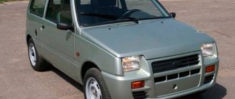
The Oka car is a widely used vehicle in the Russian Federation. The car began to be mass-produced back in the Soviet Union at the famous Volzhsky Automobile Plant.
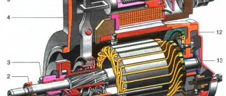
The crankcase of the power plant contains shafts driven by a gear mounted on the crankshaft. The rear crankcase cover is secured with 6 bolts. The crankcase has a magnet, which is necessary to catch metal wear debris.
It should be noted that when replacing the fuel in the box, you need to check how much debris is on the magnet. The more metal particles there are, the worse the internal condition of the box. The cooling system includes a special thermostat. The gearbox housing is made of aluminum alloy.
Depending on the modification, the Oka can be equipped with a mechanical transmission type, which can be designed for 4 or 5 speeds. The VAZ 1113 transmission includes a single-plate dry clutch. This car has a bevel differential. The gearbox is 4-speed, including synchronizers in all forward gears. On version 11116, the engine is paired with a 5-speed gearbox. The gearbox is securely bolted to the power plant. The gearbox is controlled by an installed floor lever.
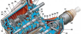
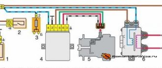
Oka checkpoint diagram
The operation of the transmission system affects the quality of acceleration and fuel efficiency. The maximum speed on this version of the domestic car can reach 140 km/h. At the same time, the acceleration of the car to hundreds, depending on the engine size available, varies within 25-30 seconds. Oka can be refilled with AI-92. At the same time, fuel is consumed almost equally in all cycles.
Main settings
The VAZ “Oka” 1111 and 11113 gearbox is a two-shaft, 4-speed gearbox, combined with a main gear and a differential. All forward gears are synchronized. The transmission of rotation to the front drive wheels from the gearbox is carried out by means of two drive shafts with joints of equal angular velocities. The weight of the unit is only 24.5 kg.
Due to the transverse location of the power plant, the gearbox is controlled remotely.
Both modifications of the small car received gearboxes identical in design, so the gear ratios are the same, the difference between the Oka gearbox 1111 and 1113 is only in the final drive indicators:
| Gear ratios "Oka" 1111 and 11113 | ||
| broadcast | 1111 | 11113 |
| 1st | 3,7 | |
| 2nd | 2,06 | |
| 3rd | 1,27 | |
| 4th | 0,9 | |
| back | 3,67 | |
| home | 4,54 | 4,1 |
The design of the gearbox is quite well developed, which ensures quite acceptable driving performance of the Oka.
What's the result?
Like any other unit, the Oka gearbox needs high-quality and regular maintenance. The owner must check the box for leaks, monitor the level and quality of transmission oil, adjust the gear shift drive in a timely manner, and perform a number of other actions and scheduled work.
- Equipment and tools
Particularly small class cars VAZ and SeAZ “Oka” 1111 and 1113 were the only models of the domestic automobile industry that were equipped with two-cylinder water-cooled power plants. These motors were very compact and structurally very well made.
But, like any power unit, Oka engines required major repairs after long-term operation. Moreover, some of the restoration work, especially the crank mechanism and the cylinder-piston group, is much easier to perform with the engine removed, so you definitely need to know how to remove the engine from the Oka. In general, removing the engine from the Oka is not a difficult operation, but you need to know the sequence of actions. You will also need the appropriate equipment.
General design of the gearbox and its drive
The box includes many components. The full list of parts is as follows:
- Frame;
- Differential bearing;
- Installation spacer;
- Grease drain plug;
- Semi-axial seal;
- Drive shaft (left);
- Gear 1st speed 2nd. shaft;
- Synchronizer clutch for 1st, 2nd speeds, as well as reverse;
- 2nd speed gear sec. shaft;
- Thrust ring;
- 3rd speed gear sec. shaft;
- Synchronizer clutch for 3rd, 4th speeds, as well as reverse;
- 4th speed gear sec. shaft;
- 4th speed gear thrust ring;
- Bearing;
- 1st and 2nd speed fork axle;
- 3rd and 4th speed fork axle;
- Deut. shaft;
- Reverse fork axle;
- Installation ring;
- Lid;
- Bearing;
- Dipstick;
- Gear 4th speed primary. shaft;
- Gear bearing;
- synchronizer ring for 3rd and 4th speeds;
- Fork;
- coupling;
- Rusk;
- Retainer;
- Plate;
- Bearing;
- Stuffing box;
- Release bearing fork;
- Clutch housing;
- Cap;
- Breather;
- Release bearing;
- Perv. shaft;
- Bearing;
- Sump;
- Main drive driven gear;
- Differential housing;
- Washer;
- Retaining ring;
- Axle gear;
- Speedometer drive gear;
- Speedometer cable;
- Drive shaft (right wheel);
- Speedometer drive housing;
- Satellite;
- Retaining ring;
- Axle of satellites;
- Anther;
- Stock;
The components of the unit are lubricated by splashing. Transmission oil is used as a lubricant; the filling volume is 1.8 liters. The amount of oil in the gearbox is checked using a dipstick.
Since the Oka gearbox has a remote control, its design additionally includes a drive for the gear selection mechanism.
The drive consists of:
- Gearbox lever (installed in the passenger compartment on the central tunnel);
- Backstage;
- 2 rods (reactive and drive lever);
- Hinge;
- A rod connected to the speed selection mechanism;
The multi-component design of the gearbox drive is not very reliable - over time, adjustment of the connections and repair of the rocker is required.
What does the Oka clutch consist of?
Let's start from the pedal and go to the very end. Firstly, a cable drive is installed on the Oka. It has several advantages. For example, low cost, ease of maintenance, ease of replacement, durability. Secondly, the clutch unit itself is double-disc, as on most modern cars. Multi-disc types are usually installed on motorcycles.
The master and slave disks are the basis of the block. The drive (basket) is screwed onto a flywheel mounted on the engine crankshaft. But the driven one is installed on the input shaft of the gearbox using only a splined connection. Another part of the assembly is the release bearing, which is necessary to press the driven disk away from the drive disk. The bearing moves along the input shaft and rotates freely.
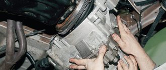
Removing the unit from the car
Thanks to its simple design, repairing the Oka gearbox yourself is quite possible. Most often, problems are caused by removing the transmission from a car, rather than repairing it.
Removing the gearbox from the Oka is possible in two ways - only the gearbox itself is removed, or it is removed together with the power plant, and only then the gearbox is disconnected from the engine and undergoes repair.
Each method has its own specific difficulties. In the first case, you have to disconnect the assembly in quite cramped conditions and require unscrewing and disconnecting many components, but the engine is not affected. If removal is carried out together with the power unit, then technical fluids need to be drained and almost all attachments must be disconnected, but removing the motor and gearbox itself is easier.
It is noteworthy that dismantling the box along with the power plant is possible in two ways - by pulling the units up (lifting devices are needed) or by lowering them down.
Removing the gearbox only
Let's look at the algorithm for removing the gearbox using an example when the engine is not affected:
- We place the car on a viewing hole, overpass, or use a lift;
- We tear off and twist the nuts securing the drive shafts in the hub;
- We hang up the front of the car, remove the front wheels;
- Disconnect the battery terminal;
- We disconnect all wires and cables from the box (“mass” wire, plug of the sensor for turning on the reverse signal light, cables);
Equipment and tools
To complete the work you will need:
- Set of open-end wrenches and sockets with cranks;
- Screwdrivers;
- Mount;
- Wooden blocks;
- Hoist or any other lifting mechanism;
Having all this, you can begin to remove the engine from the Oka with your own hands.
It should be noted that there are two ways to dismantle the power plant - lower the engine down or pull it up.
Next, we will consider the last method, which is why a lifting mechanism is needed.
Main breakdowns and their symptoms
The dismantling of the box from the car is carried out in case of certain breakdowns and the need for repairs.
The main types of breakdowns include:
- Breakdown or damage to the housing;
- Damage or wear of gears, synchronizers;
- Bearing wear;
- Bending of the forks of the control mechanism;
The gearbox will also have to be removed if the clutch components are replaced - discs (driver, driven), release bearing or its fork.
Transmission malfunctions appear quite clearly in the form of:
- Increased noise level;
- The appearance of grinding, crunching and other third-party sounds;
- Inability to engage any gear;
- Spontaneous transmission shutdown;
Other malfunctions of the unit include wear of the seals and malfunction of the drive. But these problems do not require removing the gearbox from the car, with the exception of wear on the input shaft seal (it can only be reached from the clutch housing and for this the box must be removed from the car).
Removing Attachments
Also, for the convenience of performing work, it is better to drive the car into an inspection hole. Immediately after this, the negative terminal from the battery is removed.
Before starting work, you need to drain the engine oil and coolant system.
To make it more convenient to remove and disconnect engine attachments, you must remove the hood from the car. This will provide better access to the upper hanging elements.
Then all pipes and wiring from the engine are disconnected - the cooling system pipes going to the engine from the radiator, the pipes going to the stove.
As for the wiring, you will need to disconnect all connections going to the sensors:
- oil pressure,
- coolant temperature,
- carburetor solenoid valve,
- spark torque sensor,
You will also need to disconnect the wires from the spark plugs, starter, and generator. In the future, the generator will have to be completely dismantled.
The above list of works is shown below in the photo:
You will also need to disconnect:
- fuel pipe from the fuel pump,
- brake booster hose,
- air filter housing from carburetor,
- from the carburetor itself - the throttle and air damper drive cables.
Next you need to unscrew the exhaust manifold and remove it from the studs.
In general, removal of the Oka engine should be accompanied by preliminary dismantling of the gearbox and drive, but this may not be necessary.
Since the engine will still be disassembled, the method of removing the engine without a gearbox will require removing the cylinder head before removing the engine from the car.
The above list of works is shown below in the photo:
Replacing oil seals
Most often, the drive shaft oil seals located at the installation site of the internal hinge limit switches in the gearbox must be replaced. A sign of wear is indicated by the presence of transmission oil leaks on the inner CV joint and adjacent surfaces of the housing.
Replacing gearbox seals is a relatively simple operation, but requires complete dismantling of the drive shafts.
The work algorithm is as follows:
- We install the car on the pit;
- We tear off and twist the nuts holding the drive in the hub;
- We hang up the front of the car and remove the wheels;
- We disconnect the steering tip and the ball joint from the hub;
- By pulling the hub to the side, we remove the end switch of the outer CV joint from it;
- We climb under the car;
- Using a hammer and a socket, we strike the end of the inner CV joint until the retaining ring installed on the end comes out of the groove;
- Remove the drive shaft assembly;
- Use a screwdriver to pry off the “old oil seal;
- We install a new seal using a mandrel;
- We install the drive in place;
- We assemble the car;
The technology for replacing the seal installed in the gearbox control mechanism is even simpler - disconnect the drive rods, dismantle the hinge and remove the leaking oil seal.
11.3.1. Removing and installing front wheel drives
You will need
[/td]
|
Drain the gearbox oil.
Unlock and loosen the wheel hub nut.
Remove the corresponding wheel.
If you hear knocking noises in the front-wheel drive while driving when turning the car, check the constant velocity joints. The hinge must be replaced if play is detected during rocking of the drive shaft or if the protective covers are damaged. There is no point in disassembling the hinge, since this work is labor-intensive, and if the cover is torn, dirt that has gotten into the hinge has already rendered the hinge parts unusable, which cannot be replaced individually. Therefore, it is advisable to replace the hinge assembly, as well as its protective cover. The appearance of traces of grease on the hinge indicates that the cover is torn.
If during operation you notice traces of oil leakage in the places where the front wheel drives are connected to the gearbox, replace the axle seals in the gearbox.
| Please note that the right shaft 1 drive is longer than the left one 2 . 1. Remove the brake hose seal from the bracket on the rack. 2. Loosen the locknut of the outer tie rod end, holding the hexagon of the rod from turning with a second wrench. 4. Unscrew the nut securing the ball joint of the tip. 5. Install the puller and press the ball joint pin out of the swing arm. 6. Disconnect the tie rod from the steering arm. 7. Unscrew the two bolts securing the ball joint to the steering knuckle (flat and spring washers are installed under the bolt heads) and disconnect the support from the steering knuckle. 8. Completely unscrew the hub nut. 10. Remove the shank of the outer constant velocity joint from the front wheel hub. 11. Insert a screwdriver between the reflector and the inner joint housing and, hitting it with a hammer, knock the inner joint shank out of the gearbox. 12. Remove the drive by finally removing the joint shank from the gearbox Do this carefully so as not to damage the seal. 13 Before installing the drive, the manufacturer recommends replacing the retaining ring on the inner joint shank, regardless of its condition. 14. Lubricate the retaining ring with grease and center it on the shaft to avoid damaging the ring when installing the joint. 15. Insert the shank of the inner joint into the gearbox so that its splines engage the splines of the side gear. 16. Insert the outer joint shank into the front wheel hub. 17. Using gentle hammer blows on the end of the outer joint shank along its axis, push the drive through a wooden spacer until the inner joint shank is secured in the axle gear with a retaining ring. Install all parts in the reverse order of removal. Wherein… 18. ...use a new hub nut or a nut from another wheel (so that the old crumpled part a of the nut flange does not fall into the groove b of the outer CV joint shank when cored). 19. After tightening the tip pin nut to the required torque, tighten it until the nearest slot in the nut matches the hole for the cotter pin. 20. Finally tighten the hub nut (after placing the car on the ground), lock it and install the decorative cap. Check and, if necessary, adjust the wheel alignment angles. |
Drive failures, backstage repairs
The Oka has problems not only with the gearbox, but also with its drive. The main problems with the drive are the gearshift lever dangling, and it is impossible to turn on any speed.
In the first case, the malfunction lies in the wear of the elements of the link (ball joint). Disassembly, troubleshooting and replacement of worn components allows you to fully restore the functionality of the rocker and eliminate the backlash in it, which is the reason that the lever dangles a lot.
If checking the rocker showed that it is in good condition, you should look and check the hinge mounted on the rod of the control mechanism. The same element can also cause the inability to engage gears. If its tightening clamp is loosened, then the drive rod will rotate in it, but no impact will be transmitted to the control mechanism. Checking the condition of the hinge and tightening the fasteners on it allows you to eliminate problems with the operation of the drive.
Transmission repair (Video)
VAZ cars (KAMAZ, SeAZ)-1111, 11113.
This operation is performed when the clutch does not fully engage or disengage (slips or drives) and the defect cannot be eliminated by adjustments. We have written in detail about signs of wear or clutch malfunction more than once, for example, in magazine No. 9 for 1995 and in No. 12 for 1996.
To dismantle the clutch on the Oka, no special tool is required. A set of wrenches, sockets with extensions and universal joint are required, as well as a mandrel to center the clutch disc on the flywheel during assembly. Attention! The repair manual says that you can use a “Zhiguli” mandrel, but this is not true. “Oka” needs its own, special one. We selected a tall head from the tool kit for this purpose. In general, you can even plan a mandrel from a piece of wood.
It is better to carry out work on a ditch or a lift together with an assistant. We start with operations under the hood of the car.
Disconnect the negative wire from the battery and the connector with wires from the spark torque sensor.
Using a “13” wrench, unscrew the nut of the “positive” wire on the starter and disconnect it along with the power wire of the traction relay.
Using pliers, unscrew the nut of the speedometer drive cable and disconnect it from the gearbox.
Using a 10mm wrench, loosen the nut securing the clutch cable guide.
Unclench the latch holding the leash on the clutch release fork, and, raising the clutch pedal all the way, remove the leash along with the cable from the clutch release fork.
Using a 17mm wrench, unscrew the nut securing the cable to the bracket on the gearbox. Remove the cable from the bracket.
Using a 17mm wrench, unscrew the two upper bolts securing the gearbox (clutch housing) to the engine block.
One of these bolts secures the top of the starter to the box. The third bolt securing the gearbox to the engine is located under the starter. To access it you need to remove the starter.
Power plant and transmission on Oka
The VAZ 1111/1113 car can be equipped with a two-cylinder engine. The automotive system has a reaction rod, which is located in the gearbox control drive.
The crankcase of the power plant contains shafts driven by a gear mounted on the crankshaft. The rear crankcase cover is secured with 6 bolts. The crankcase has a magnet, which is necessary to catch metal wear debris.
It should be noted that when replacing the fuel in the box, you need to check how much debris is on the magnet. The more metal particles there are, the worse the internal condition of the box. The cooling system includes a special thermostat. The gearbox housing is made of aluminum alloy.
Depending on the modification, the Oka can be equipped with a mechanical transmission type, which can be designed for 4 or 5 speeds. The VAZ 1113 transmission includes a single-plate dry clutch. This car has a bevel differential. The gearbox is 4-speed, including synchronizers in all forward gears. On version 11116, the engine is paired with a 5-speed gearbox. The gearbox is securely bolted to the power plant. The gearbox is controlled by an installed floor lever.
The operation of the transmission system affects the quality of acceleration and fuel efficiency. The maximum speed on this version of the domestic car can reach 140 km/h. At the same time, the acceleration of the car to hundreds, depending on the engine size available, varies within 25-30 seconds. Oka can be refilled with AI-92. At the same time, fuel is consumed almost equally in all cycles.
Features of repair and maintenance
Like any internal combustion power plant, the VAZ-1113 engine required periodic maintenance, and after its service life was exhausted, a major overhaul was carried out or a complete replacement of the engine on the Oka.
Overhaul of the Oka engine is carried out in case of severe wear of the cylinder-piston group and the crank mechanism. Moreover, although the engine life is approximately calculated by the manufacturers, it is greatly influenced by the characteristics of operation, the frequency of maintenance, as well as the quality of the technical fluids and fuel used.
In most cases, Oka engine repairs are performed without removing it from the car. In a number of systems and mechanisms, it is possible to remove components from the power plant for subsequent restoration or replacement, or even do everything on the unit. This applies to power systems, ignition, starting, electrical supply, cooling, as well as the gas distribution mechanism.
But removing the motor and disassembling it will be necessary if it concerns the cylinder-piston group and the crank mechanism, which includes the balance shaft system. As for the latter, they are a design feature of the two-cylinder engine.
The fact is that the pistons in Oka installations move in pairs, not separately. But at the same time, the power strokes in the cylinders are performed differently. For example, both pistons move upward, but in the first cylinder there is a compression stroke, and in the second - an exhaust stroke. After passing through the VTM, the first cylinder has a working stroke, and the second one has an intake stroke, and so on in a circle.
The balancing system prevents the occurrence of increased vibrations, which necessarily arise with such design and operation features of the power plant.
If the power unit has exhausted its resource, that is, the wear of the cylinder-piston group has reached critical values, or a serious breakdown of the crankshaft has occurred, the engine is overhauled. In this case, all work can be performed only on a removed installation.
Next, we’ll look at how to properly remove the power plant from the engine compartment of this car with your own hands, without resorting to the services of a service station.
Gearbox failures
When is gearbox repair required? The owner of the vehicle must check the box if the following signs appear:
- difficult gear shifting;
- spontaneous activation of gears;
- noises from the box;
- There is an oil leak.
With any of the listed manifestations, it is advisable to pay attention to bearings, gears, and synchronizers.
In some cases, transmission breakdowns on a car can be caused mechanically. In particular, the clutch housing can break if, during a trip, the car collides with an external obstacle, for example, a curb. Also, a problem with the clutch housing may be a result of wear on the secondary shaft. Movement will be complicated if the crankcase has cracks.
It is necessary to repair the gear shift lever if it begins to move with difficulty. In this case, installing a new ball joint or spring, as well as a spherical washer, can help. If the lever is worn, it is worth replacing it.
Carrying out repairs yourself is a real task.
Replacing the clutch disc with your own hands: photo, video
The mechanism for connecting the engine flywheel to the gearbox is one of the elements of the transmission of any vehicle, including a car. The entire structure of this unit is in direct contact with the crankshaft of the machine and is subject to great mechanical stress during operation.
As the discs, release bearing or clutch wear out, an operation such as clutch replacement becomes necessary. It can be done either with the help of specialists at a car service center or independently, with your own hands.
Design of the mechanism for connecting the internal combustion engine and transmission of a car
- according to the nature of friction, it can be dry, that is, the clutch basket and friction disc work in an air environment, and wet - when the clutch elements are immersed in an oil bath;
- By the number of driven or friction disks, single-, double- or multi-disk devices are distinguished;
- These units are distinguished by the drive with which they are controlled - this is a mechanical, hydraulic, pneumatic or combined method of controlling the mechanism.
How do malfunctions in the connection mechanism between the internal combustion engine and the gearbox manifest themselves?
- The elements of this system are not fully activated, so-called “slippage” occurs. When the drive pedal is completely released, the driven disc and clutch basket slip relative to each other. In this case, at high speeds when pressing the gas pedal, the speed does not increase.
- When the pedal is pressed, the clutch basket does not disengage completely. A situation arises when the mechanism “drives.” In this case, when the gears are engaged, a crunching sound is heard in the box due to the turning gears.
- Jerking appears when the drive pedal is fully released. This is possible when the friction linings wear out, the springs break, and also if the clutch or release bearing breaks.
Transmission repair needed
What tools are required when surveying a checkpoint on the Oka?
When carrying out this process, you will need a set of wrenches, a screwdriver, a hammer, and pliers for installing the retaining rings.
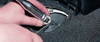
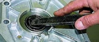
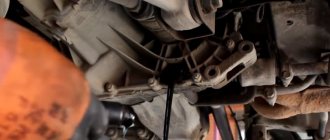
To begin repair and restoration work, you need to remove the speed box. However, it is recommended to drain the oil before doing this. When disassembling the gearbox, you need to unscrew the rear crankcase cover, retaining rings, and retainer plugs. The next step is to disconnect the gearbox housing from the clutch housing. You can use a screwdriver specifically for this. The gear shift fork mounting bolt must be unscrewed. The rod is removed along with the plug. Next, you need to remove the locking pin, then dismantle the shafts, remove the plungers, and the differential. The subject to be photographed is the magnet that is present in the clutch housing. Finally, the gear selection mechanism is removed.
The Oka has a special gear selection mechanism, which includes:
- frame;
- reverse gear fork;
- springs;
- lever arm.
In order to repair this mechanism, it is necessary to dismantle the speed box. Next, during disassembly of the gearbox, the device itself is removed. When reassembling the gear selection mechanism, you should pay attention to the springs; there are two of them (upper and lower). One of them is galvanized, the other is not. The non-galvanized spring is the top one. In addition, they differ in elasticity.
The occurrence of grinding noise can be eliminated by adjusting the clutch. There are several reasons why noise occurs. One of them is that the gear oil has lost its working properties. Also, a low fuel level may cause extraneous noise.
If spontaneous gear disengagement occurs, the driver of the car must check the condition of the clutch housing. However, there are many reasons why gears suddenly switch off, ranging from the presence of worn bushings to deformation of the lever fork.
Replacing the clutch without removing the gearbox on an Opel F13 gearbox
This article will talk about an amazing procedure for replacing the clutch without having to remove the gearbox. On Opel's 2-liter 8-valve engines, with the brands C20NE or X20SE, F13 gearboxes are installed. The engines themselves are found on cars such as Opel Vectra, Omega, Askona, Calibra, Kadett, Frontera (in “GT” trim levels), some Daewoo models: Espero, Leganza and so on.
The design of the above-mentioned gearbox is no different from all existing gearboxes, however, its thoughtful assembly allows you to replace the driven disk along with the basket in half an hour, saving a lot of time, and most importantly, nerves. Having done this kind of work, I was left with a very pleasant impression. Let's move on to the process itself.
To begin with, we set the gear to neutral, jump under the car and unscrew the bottom hatch located in the bell box. This is precisely our very happy window through which the replacement will be made.
First, the clutch driven disc must be released. To do this you will need 3 homemade staples. They are made of metal with a thickness of at least 3 mm, otherwise the basket will simply bend them. The bracket is made with your own hands or from a familiar turner. Its width is about 3 cm, length is almost 3 cm, and the distance between the curved parts is approximately 17 mm. On one side of each bracket, 8 mm holes are made in the center and cuts are made with a grinder. This is necessary so that when driving the staple onto the basket, the staple will go through the rivet (I will attach a photo of the removed basket). The brackets are put on the body of the basket with the driven disk, that is, the brackets will hold the driving disk pressed or, more simply put, it will have the same effect as when the clutch pedal is depressed. Let's get down to business. An assistant should depress the clutch and keep the pedal depressed until you put the bracket on. The staple should go a little tight, so you can and should help it a little by tapping with a hammer. The first bracket was put on - the assistant released the pedal, the basket was turned, and thus we put on the second and third brackets. Since there are 3 of them, they are put on every 120 degrees.
The driven disk has been freed (it should be hanging on the input shaft), now we move to the rear of the gearbox. On some modifications there is a plug opposite the input shaft on the fifth gear hatch, but on some there is none. If there is a plug, then it can be unscrewed with a hexagon; if it is not there, you will have to unscrew the entire hatch. Answering the question whether it is worth draining the oil from the box when removing the hatch, I will say that in general, there is no need. A maximum of 50 grams will leak out, so just replace the container and then it will be easier and faster to pour these 50 grams through the filler plug.
The next photo shows the removed hatch without the plug. That's it, unscrew the plug or the entire hatch. Now in the center, where the primary shaft runs in the secondary shaft, a locking ring is pulled out, holding it from axial movement, and then the bolt for the 12-point TORX sprocket is unscrewed. Since the input shaft is completely free, a regular nut bolt is screwed into the place where the TORX bolt was unscrewed, preferably a long one so that you can pull it to pull out the input shaft. If there is no suitable bolt, then you can make it yourself or again turn to a familiar turner. The thread should be 11, with a pitch of 1. To pull the shaft, for convenience, special handles made from scrap materials were attached to the stud.