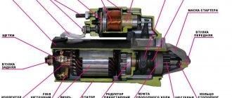
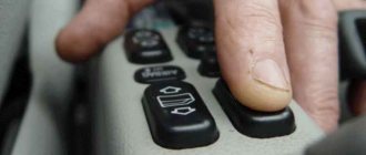
Starter of the OKA VAZ-1111 - 1113 type 39.3708 : 1 - overrunning clutch; 2 - restrictive ring; 3 - drive gear; 4 - drive side cover; 5 — drive lever; 6 — relay anchor; 7 - relay holding winding; 8 - relay pull-in coil; 9 — contact plate; 10 — relay cover; 11 — contact bolts; 12 — casing; 13 - collector; 14 — back cover; 15 — brush; 16 — body; 17- pole; 18 - anchor.
Starter type 39.3708 is a four-brush DC electric motor with mixed excitation and an electromagnetic two-winding traction relay.
Technical characteristics of starter 39.3708:
Rated power, kW 0.9 Current consumption at rated power, A, no more than 230 Current consumption in the inhibited state, A, no more than 310 Current consumption in idle mode, A, no more than 60
Four poles with field windings are secured in the starter housing with screws:
three series (connected in series) and one shunt. The body and covers are secured with two bolts. The anchor is with an end commutator. The rear end of the armature shaft rotates in a metal-ceramic bushing pressed into the cover, and the front end rotates in a bushing pressed into the clutch housing. (When installing the starter, make sure the bushing is in place.) The drive shaft has a freewheel (overrunning clutch) with a drive gear. It transmits torque in only one direction - from the starter to the engine, separating them after the engine starts. This is to protect the starter armature from damage due to excessive speed. The traction relay is used to engage the drive gear with the ring gear of the engine crankshaft flywheel and turn on the power to the starter motor. When the ignition key is turned to the “starter” position, voltage is supplied through an additional relay type 113.3747-10 to both windings of the traction relay (retracting and holding). After closing the contacts of the traction relay, the retractor winding is turned off. The operating voltage of the traction relay should be no more than 9 V at (20±5)°C. If this is not the case, there is a fault in the relay or actuator. The serviceability of the drive is determined by inspection after disassembling the starter. The faulty relay is replaced. On some vehicles, a starter type 1111.3708 with a rated power of 1.0 kW is installed with excitation from permanent magnets (it does not have poles with windings). Six segment magnets are located on the inner surface of the starter housing and are held in place by two plastic holders located near the covers. The covers are secured with two pins, the latter also securing the pole holders.
OKA starter parts with codes:
1111-3708020 Lever 1111-3708043 Cap 1111-3708100 Housing assembly 1111-3708110 Series pole coils 1111-3708160 Parallel pole coils 1111-3708200 Armature 1111-3708300 Cover 1 111-3708340 Brush with tip 1111-3708350 Insulated brush 1111-3708401 Cover 1111 -3708600 Drive 1111-3708800 Starter relay 2101-3708418 Cover plug 2101-3708676 Gear travel limiter 2101-3708678 Retaining ring 2108-3708081 Tie bolt
Motors 1111 and 1113 are started using a powerful starting electric motor, which has a remote control. The VAZ 1111 Oka starter spins the flywheel at a speed of up to 300 rpm, thereby creating the necessary conditions for the start of the power stroke.
Models, characteristics, location
The designers did not borrow a starter from other VAZ models, but made a new one - for Oka engines. The impossibility of unifying starters for owners of this small car often results in problems, since the “native” starter is not a particularly reliable unit.
It is noteworthy that Oka’s power electric motors were produced by several manufacturers. The most common is the unit with the factory index 39.3708 (KZATE Samara plant), which we will consider in the future. Also, the VAZ-1111 was equipped with Belarusian-made components (1111-3708010-5) and Slovenian ones - AZE-1517.
The main characteristics of model 39.3708 are as follows:
- Power – 0.9 kW;
- Current consumption – 230A;
- Weight – 5 kg;
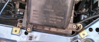
This unit is mounted on the left side of the engine (in the direction of travel) above the gearbox, and the thermostat housing is located above it. Fixation is carried out with only two fasteners - a bolt and a nut, with which the starter is attracted to the clutch housing. This arrangement is convenient because you can dismantle the unit from the car without removing anything additional.
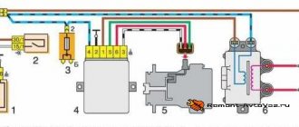
Electrical diagram of SeAZ-11116
On SeAZ-11116 cars with a Europanel and a Chinese 3-cylinder engine, the electrics have undergone changes.
The cars use an electronic instrument cluster, which has led to the emergence of a number of new sensors. The fuel supply system was changed, into which a fuel pump with a control relay was introduced. Big innovations appeared in the engine compartment, where a fuel injection and ignition control system began to be installed. At the same time, the main part of the wiring, the fuse and relay box was carried over unchanged from the old carburetor version. The diagram shows the following electrical equipment components:
| Number on the diagram | Element designation |
| 1/1 | High beam thread |
| 1/2 | Low beam thread |
| 2 | Front turn signal lamp |
| 1/4 | Side light |
| 3 | Side repeater |
| 5 | Generator and built-in relay regulator |
| 9 | Hall Sensor |
| 10 | Ignition coil |
| 12 | Starter |
| 13 | Spark plug |
| 14 | Klaxon |
| 17 | Coolant temperature sensor |
| 18 | Sensor for determining emergency oil pressure |
| 23 | Battery |
| 25 | Reversing signal switch |
| 26 | Device for turning on and off brake signals |
| 30 | Turn signal control relay |
| 31 | Parking Brake Warning Indicator Controller |
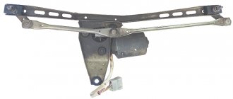
| 32 | Block for changing the operating mode of the windshield wiper |
| 33 | Additional heater motor resistor |
| 35 | Windshield wiper drive motor (front) |
| 37 | Heater fan motor |
| 38 | Radiator impeller drive |
| 39 | Cooling system motor control relay |
| 42/1 | Steering column turn signal switch |
| 42/2 | A similar element for headlight modes |
| 42/3 | Steering column for controlling the windshield wiper and washer |
| 42/4 | Steering wheel button for horn |
| 44 | Egnition lock |
| 46 | External lighting control (dimensions) |
| 48 | Alarm management |
| 49 | Switching heater fan speeds |
| 52 | Instrument cluster |
| 63 | Speed sensor |
| 74/1 | Cigarette lighter |
| 74/2 | Cigarette lighter socket illumination system |
| 75 | Fluid volume measuring sensor in the brake drive |
| 76 | Parking brake limit switch |
| 77 | Diagnostic connector |
| 81 | Portable lamp socket |
| 83 | Washer pump drive |
| 87 | Limit switch for interior lighting system (on the door) |
| 89 | Interior lighting |
| 93 | Sensor measuring fuel level (with backup indicator) |
| 98/1 | Rear light size |
| 98/2 | Turn signal located in the stern lights |
| 98/3 | Brake lamp |
| 98/4 | Reverse gear indicator |
| 99 | License plate light |
| 104 | Radiator Fan Thermal Switch |
| 108 | Rear fog light |
| 112 | Tail wiper motor |
| 113 | Rear window washer motor |
| 115 | Rear window heating filaments |
| 121 | Heated glass controller |
| 125 | Additional relay |
| 126 | High beam controller |
| 127 | Similar device for low beam |
| 129 | Starter controller |
| 133 | Heated rear window switch |
| 136 | Tail fog control |
| 137 | Rear window wipe control |
| 138 | Turning on the tailgate glass washer |
| 158 | Fuel injectors |
| 159 | Watch |
| 168 | Rear Fog Lamp Controller |
| 169 | Third brake light |
| 170 | Fuel pump controller |
| 171 | Fuel pump |
| 172 | Idle speed control system |
| 173 | Throttle valve angle sensor |
| 174 | Knock sensor |
| 175 | Canister purge system |
| 176 | Lambda probe |
| 177 | Absolute pressure sensor |
| 178 | Main relay |
| 221 | Engine control system controller |
Starter for OKU: what cars is it suitable for?
One of the significant disadvantages of the Oka starter is the absence of the so-called “dome”. In those nodes where it is present, the “dome” acts as a second reference point for the anchor. In Oka, due to the absence of this component, the second support for the shaft is a recess in the engine block. The support sleeve is also installed in it. Therefore, if the bushings wear out - and this is the most common malfunction - replacing them becomes a serious problem for the owner.
OKA starter catalog number: 391.3708 - if you decide to install the same one.
One of the options for solving problems with bushings is to install a starter from another car on the Oka. As a replacement, you can use the VAZ-2110 starter, which has a “dome”.
But in order to install a “ten” starter, you will have to make certain modifications to the unit itself, as well as the clutch housing, for which you will have to remove not only the starter itself from the car, but also disassemble the transmission - remove the gearbox, clutch and dismantle the clutch housing.
To install the VAZ-2110 starter on the Oka, you need to use a grinder. machine to grind the surface of the “dome”, thereby reducing its diameter. You will also have to cut the mounting lugs.
In the crankcase, you need to cut out the partition from the inside and grind the surfaces adjacent to the mounting hole.
All these modifications are aimed at ensuring that the new unit fully “fits” into the crankcase hole.
Some craftsmen, instead of the “native” starter on the Oka, even installed a unit from a VAZ of the classic family, the same VAZ-2106. But in this case, the improvements were significant, since the starter from the “classic” is larger. The installation issue in this case was resolved by using an adapter plate.
Mounting fuse block VAZ 2114
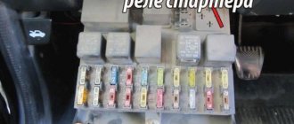
In cars like VAZ 2114 there are two fuse blocks - main and auxiliary. The first is located near the motor and contains fuses responsible for protecting the main equipment. The second part is hidden in the cabin and plays an auxiliary role.
Main unit
To access the panel, unclip the cover and remove it. The fuse links and relays will open inside.
The main control elements of power circuits and equipment are concentrated here.
Additional block
To open the additional block you will need to use a screwdriver. The panel is located at the front passenger's feet and is covered with a plastic cover. The protection is held on by 4 screws, and you need to unscrew them. Next, the user has access to the protection elements of the auxiliary circuits.
Typical faults
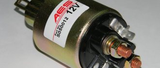
- Failure of the starter solenoid relay - the integrity of the relay winding may have been damaged or there may have been a short circuit, which led to the destruction of the internal structures of the structure. The malfunction is eliminated by diagnosing the relay and replacing the part with a new one if necessary;
- Broken contacts in the starter electrical circuit - a typical situation in this case is corrosion of the wires or insufficient tightening of the fixing bolts. The cause of the problem is insufficient ground capacity, which is eliminated by replacing damaged electrical circuit parts with new ones. To more easily diagnose a malfunction, it is recommended to test the circuit using a multimeter, having first disconnected the battery;
- A short circuit in the winding of the device is a rather rare problem, to solve which you will have to install a new starter. Most often, a short circuit is observed in devices that have operated for a sufficiently long period, as a result of which the internal part of the housing insulation has been worn away, which led to a short circuit. In the event of a short circuit, there is no point in sending the starter for repairs - it’s easier to buy a new device;
- Slipping of the freewheel clutch of the starter drive - a clear sign of a malfunction of the clutch is the absence of “torsion” of the starter. To eliminate the malfunction, you will have to replace the mechanical drive of the device, and also check the solenoid relays for possible short circuits.
Also, unstable operation of the starter can occur due to a mismatch in the battery charge level or insufficient viscosity of the engine oil, which is especially important in the cold season. Before mechanical diagnostics of the internal combustion engine and adjacent systems, it is recommended to check the oil and battery charge.
Note! The inability to start the vehicle is not always the cause of starter failure - perhaps the problem lies in the relay or broken wiring. A clear way to check the functionality of the device is to start the car engine by connecting direct contacts to the starter - if the car starts, perhaps the problem should be looked for in the relay or on the current lines
Lada Oka OKaYbAcH PiCk-Up › Logbook › “the stingy one pays...” or rebuilding the starter on your own!
Hi all! Finally I made this damn starter! I'll tell you briefly how it all happened. After driving around, the car refused to start and I naturally went to the store to look at the price of the issue. The price shocked me - 2600 rubles! I bought it cheaper at 2112. I decided to look for a used one and found it for 800 rubles from a company called Katya, basically a famous company for basins, it’s like luzar pumps, only with a starter!), and so I bought it. So I came to the garage, started installing it, while I was tightening the wires on the solenoid relay, I broke the partition, some kind of spring flew out, well, I wasn’t at a loss and decided to start it, check, maybe to hell with it) my brother stood watching, I started it... I heard a cry: “ GOOD, THERE IS A SPARK HERE.” ummm. I went to get a new retractor - I paid 500 rubles, I was happy, I thought that was it! go! I turned the key once, twice, three times, and it started. But the Bendix (gear on the starter) spun at idle and did not engage the flywheel. There was a lot of swearing, sadness, but nothing. I went home in my faithful friend Chrysler) I looked on the Internet, corresponded with Tokha and decided to change the Bendix. (350r) starter analysis:
1. Unscrew the bolt securing the wire connecting to the starter. 2. unscrew the 2 bolts (which hold the solenoid relays
4. Unscrew the 2 long bolts from the butt of the starter. and take out the “front part with bendix”, be careful, you can pull the lower part and your brushes will fall out, but we don’t want that!
5. put the rotor aside and take the front part 6. We knock off the washer on the retaining ring, by the way the retaining ring is not even visible because of this crap 7. Well, we pick out the retaining ring, I almost lost my fingers!)))))
8. We take everything out and go to the store to pick it up)
9. Reassemble everything in reverse order. In the end, I spent 1,700. I had to get a new one!)))) Today we also had time to mock on the track, and in the swamp) as always, everything is fine, but apparently I tore off my pants, now the TAZ is screaming like a cool guy, but it’s not moving! :DDD I also fixed the electrics, now everything works like a charm) and I’m slowly dismantling the interior) I decided that I’ll leave part of the torpedo, and make part of it from aluminum, and instead of the standard buttons, I’ll put a toggle switch. I’ll also soon make a snorkel, and then raise it), everything is ready for the rear suspension... but the muzzle is waiting for its time) By the way, we should bring the material for the bumpers in the near future) Okay, good luck to everyone, bye!)
Source
Main malfunctions and why the starter does not turn?
Malfunctions of the Oka starter, as well as the power electric motors of cars, are divided into two categories - mechanical and electrical. The first includes:
- Wear of armature support bushings;
- Damage to gear teeth;
- Jamming of the retractor relay armature;
- Development of splines for the armature shaft;
The most common mechanical failure is wear of the support bushings, which subsequently becomes the cause of other breakdowns. Due to significant wear of the bushings, the position of the armature and, accordingly, the bendix are disrupted. As a result, it is more difficult for the gear to engage, the wear rate of the teeth increases, and they may crumble.
Electrical faults include:
- Breakage of stator windings, armature, solenoid relay;
- Heavy wear of collector plates;
- Critical wear of brushes;
- Closing the windings;
- Burning of “nickels” of power contacts;
To this category of breakdowns you can also add problems with the power circuits of the electric motor and relay.
Malfunctions of the Oka starter manifest themselves in different ways:
- The starter does not turn on, there are no additional sounds;
- You can hear the activation of the solenoid relay, but the electric motor does not turn;
- The starter rotates, but picks up speed;
- Extraneous sounds are heard when turned on (crunching, grinding);
If such signs occur, the unit should be repaired.
Maintenance, repair
Of all the car’s electrical appliances, only power supplies require maintenance:
- Battery (periodic recharging using chargers, monitoring the level and density of the electrolyte);
- Generator (periodic check of drive tension, replacement of worn graphite brushes).
It is also important to monitor the condition of the wire insulation and prevent it from being damaged to avoid a short circuit. Oxidation of contacts often occurs at the wiring junctions, which can lead to failure of electrical appliances
Most of the electrical network components are maintenance-free and must be replaced if they fail. Such elements include light bulbs, small electric motors, switches, relays, fuses, and sensors.
In the starter, generator, electric. In the heater and cooling system fan motors, mechanical breakdowns may occur - wear of bearings, bushings, brushes. All these components are repairable and it is often possible to restore their functionality by disassembling, troubleshooting and installing new parts to replace worn ones.
Design
The starter on the Oka is a commutator electric DC motor. Its main components are:
- Stator with field windings;
- Brush holder (brush assembly) with 4 graphite brushes;
- Anchor;
- Bendix (drive gear with freewheel);
- Solenoid relay with drive plug;
- Lids;
All elements are assembled into a single structure and secured with coupling bolts.
The stator due to the passage of electrical energy through its windings, ensures the emergence of an electromagnetic field. The second magnetic field is created by the armature winding. Electric current is supplied to it through graphite brushes to the commutator, to the plates of which the ends of the armature winding are soldered. The magnetic fields generated around the windings lead to the rotational movement of the armature.
On one side of the armature shaft there are splines on which a bendix is mounted, consisting of a gear and an overrunning clutch. Bendix has the ability to move along the shaft, and due to the spline connection, rotation is transmitted to it.
The Bendix gear is designed to engage with the crankshaft flywheel and transmit rotational motion to it. By default, the gear is not engaged with the flywheel and there is no interaction between the engine and the power electric motor.
The task of the overrunning clutch is to interrupt the transmission of rotation after starting the power unit. Even at minimum speeds, the rotation speed of the crankshaft is higher than the starter speed, so after starting the engine, reverse rotation is transmitted - from the flywheel to the electric motor. engine (until the gear is disengaged), which significantly reduces the service life of the starter. To prevent this negative effect, the gear interacts with the armature shaft not directly, but through a roller clutch, consisting of two cages and rollers placed between them.
The essence of the clutch is this: while the rotation speed of the starter armature is higher than that of the flywheel (the engine is not running), the rollers “jam” the cages among themselves, thereby transmitting rotation to the gear. As soon as the engine starts and the flywheel accelerates, one of the races moves relative to the second and the rollers “wedging” occurs, due to which the transmission of rotation from the gear to the armature is interrupted.
The movement of the bendix along the shaft splines is carried out by a retractor relay installed on the starter housing. This unit is also “responsible” for supplying electricity to the electric motor windings.
The peculiarity of the starter is that the gear is first engaged, and only after that the electric motor is turned on. And all this is provided by the retractor relay.
The relay consists of a housing with windings located inside, a contact disk and power contacts (“nickels”), as well as an armature that engages with a fork that interacts with the bendix.
Photo gallery "Main components"
As for the drive, or as it is commonly called, the Bendix, this element is a freewheel, and at one end there is a drive gear. The design of the starter mechanism provides for the presence of a coupling, which is necessary to supply torque in one direction from the unit to the power unit. When the unit is started, the mechanism will be disconnected from the motor. The purpose of the relay is to feed the gears of the drive element into connection with the flywheel.
Briefly about the principle of operation:
- The driver turns the key to the Start position.
- The mechanism relay supplies power to the winding elements, and then to the windings of the traction relay.
- As a result, an electromagnetic field is formed, which promotes retraction of the core. Gear starter Oka LSt leading position on the starter is not suitable for. When this element is retracted, a drive lever is pulled behind it, the purpose of which, as stated above, is to engage the gear of the device with the flywheel.
- When the core is fully retracted, as a result of the movement of the plate, the contacts close, which leads to the supply of voltage to the windings of the electric motor. At this moment, the winding is also de-energized.
- When the power unit is started, the overrunning clutch comes into operation, which breaks the supply of torque from the power unit to the anchor element. Thus, it prevents damage to the latter. When the engine is started, the key will exit the Start mode, which will open the contacts on the relay. The heart element returns to its original position.
Starter VAZ 1111
The starter is a structural part of the vehicle ignition system, the functional purpose of which is to generate a powerful starting current necessary to rotate the flywheel to half a turn.
The principle of operation of the starter design is to increase the current power by passing electrical energy through the winding of the part, as a result of which magnetic fields contribute to the rotational movement of the armature.
Due to some design flaws, the original starter model for the Oka is not particularly reliable, which often leads to problems when starting the car’s power unit.
Connection diagram. Principle of operation
The starter is powered from the on-board network as follows: a large cross-section wire is laid from the “positive” terminal of the battery to one of the contacts of the solenoid relay. From the second contact of the relay there is a bus to the brush holder and stator windings. This circuit is the main one for powering the electric motor, but there is a break in the relay, which prevents the constant supply of current to the windings.
From the same “positive” terminal there is another wire, passing through the additional relay, the ignition switch and leading to the solenoid relay. The task of this circuit is to power the relay windings.
To turn on the starter, the driver must set the key in the lock to position “2”. Thus, it closes the power circuit of the solenoid relay, and current flows to its windings. As a result, a magnetic field arises, which leads to the movement of the relay armature - it is “pulled” into the housing.
Moving inside the body, the anchor pulls the fork along with it, and it moves the Bendix along the splines of the armature shaft, engaging the gear with the flywheel.
At the same time, the anchor pushes the rod on which the contact disk is fixed. Having reached the stop, this disk is pressed against the “nickels” of the power contacts, as a result of which the electrical power supply circuit is closed. engine, and it begins to rotate, and the gear will already be engaged.
After starting the Oka motor, the clutch is activated, preventing reverse rotation.
By returning the key to position “1”, the driver opens the relay power circuit, the return spring “pushes” the armature. Moving back, it stops acting on the rod of the contact disk, due to which the electrical power supply circuit is opened. engine. At the same time, the anchor pushes the fork, and it disengages the bendix.
Device and electrical diagram
The starter from KZATE has a simplified design of a conventional commutator electric motor. The main details are:
All elements are assembled in a housing, the covers are secured with studs and bolts. The starter on the VAZ 1111 is powered from the on-board network. The scheme is implemented as follows. The control cable is routed from the battery to one of the contacts of the traction relay. Next, from the retractor there is a bus to the starter brushes and windings. It turns out the main chain, but there is also a break in it. It is needed to eliminate the constant supply of voltage to the windings.
The additional power circuit starts from the positive terminal through an additional relay, the ignition switch and closes at the solenoid relay. The task is to provide power to the relay windings.
8.2.8. Starter repair
- key "8"
- screwdriver
- electric soldering iron
1
- cover on the drive side
2
- drive gear
3
- armature shaft
4
- housing
5
- cover on the commutator side
6
- traction relay
1.
Unscrew the nut of the lower contact bolt of the starter traction relay.
2.
. remove the washer and disconnect the stator winding terminal tip.
3.
Remove the two starter traction relay mounting nuts (one shown).
4.
Remove the traction relay from the cover on the drive side.
5.
Remove the traction relay armature from the cover on the drive side, disengaging it from the drive lever.
6.
Remove the drive lever stop by prying it off with a screwdriver.
7.
Unscrew the two coupling bolts and...
8.
. Remove the cover from the manifold side cover.
9.
Remove the casing gasket.
10.
Remove the brush springs from the brush holder.
11.
Remove the lock washer from the starter armature shaft and.
12.
. adjusting washers.
13.
Separate the starter housing and the cover on the manifold side (if this cannot be done by hand, use a screwdriver).
14.
Remove the insulated brushes from the brush holder and.
15.
. Remove the starter cover from the manifold side.
16.
Remove the spacer washer from the armature shaft.
17.
Remove the cotter pin securing the axis of the starter drive lever and.
18.
. Remove the axle from the drive side cover.
19.
Remove the drive side cover.
20.
Remove the starter drive lever.
21.
Remove the starter armature from the housing.
22.
Slide the restrictor ring away from the retaining ring.
23.
Remove the retaining and limiting rings from the armature shaft.
24.
Remove the starter drive clutch assembly from the armature shaft.
25.
Remove the spring from the traction relay.
26.
To replace the brushes, remove the insulating bracket.
27.
. Use a soldering iron to heat the junction of the insulated brushes with the stator terminal and, using a screwdriver, open the bend of the stator terminal.
28.
. remove the insulated brushes.
29.
Unscrew the screws securing the ends of the non-insulated brush bars and remove the brushes from the cover on the commutator side.
Defective starter parts
30. Check the condition of the stator winding. To do this, turn on the test lamp (designed for a voltage of 220 V) into an alternating current network with a voltage of 220 V and connect one wire to one of the terminals of the stator winding, and short the other to the housing. If the lamp is on, the winding insulation is damaged. Replace winding or stator. Also check the other stator winding
When testing with 220V voltage, be careful. Do not touch live parts of the stator with your hands.
31.
Inspect the surfaces of the armature shaft under the bearings. If you find yellow deposits from the bearings on the armature shaft, remove it with fine sandpaper. There should be no damage on the surface of the shaft splines (burrs, nicks, chipping of teeth and visible signs of wear).
32.
Check the reliability of soldering of the armature winding leads to the commutator plates.
33.
The sealing gasket of the starter casing must not be damaged (ruptures, cracks, etc.).
34.
Check the starter drive by turning the gear (it should only rotate in one direction). If drive parts are severely worn or damaged, replace the drive. If you find nicks on the leading part of the teeth, grind them with a fine-grained wheel of small diameter.
35.
Check the condition of the traction relay armature spring. Replace the broken spring.
36.
The starter coupling bolts should not have severe damage to the threaded part and heads.
37.
Check the condition of the starter cover on the drive side. The presence of cracks is not allowed.
38.
Inspect the surface of the traction relay armature. Deep risks and bullying are not allowed. the anchor should move in the traction relay easily, without jamming.
39.
The starter drive lever forks must not be bent.
40.
Check the condition of the starter brushes by measuring their height. It must be at least 12 mm.
41.
Check the closure of the contact bolts of the traction relay with the plate. To do this, connect an ohmmeter to the contact bolts and press the rod of the traction relay (from the flange side). If the ohmmeter shows “infinity”, replace the traction relay.
42.
Check the condition of the inner surface of the traction relay. Risks, bullies, etc. not allowed.
Starter assembly
Assemble the starter in the reverse order of disassembly, taking into account the following features.
43.
Clean the surface of the starter armature commutator.
44.
Lubricate the splined part of the armature shaft with engine oil.
45.
. bearing-sleeve cover on the collector side and.
46.
. starter drive sliding surface.
47.
Press in the restrictive ring after installing the retaining ring on the armature shaft.
48.
Lubricate the drive ring of the starter drive with Litol-24 grease.
Copyright 2007-2019 All rights reserved. All trademarks are property of their respective owners.
Video “We repair the mechanism with our own hands”
Detailed repair instructions are given in the video below (by Sergey Neverov).
The starter is removed for repair or replacement, as well as when removing the gearbox.
The main malfunctions in which the starter should be removed for inspection and repair:
1. When turning on the starter:
– the armature does not rotate, the traction relay does not operate;
– the armature does not rotate or rotates too slowly, the traction relay is activated;
– the traction relay is activated and switched off repeatedly;
– the armature rotates, the engine flywheel does not rotate.
2. Unusual starter noise when the armature rotates.
Before removing the starter, make sure that the indicated malfunctions are not caused by other reasons (discharged battery, oxidation of leads, terminals, broken electrical connections, etc.).
You will need: keys “13” and “17”, a screwdriver.
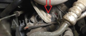
The starter is located under the cooling system thermostat, secured with a bolt and nut to the clutch housing.
1. Disconnect the wire from the “–” terminal of the battery.
2. Remove the protective cap from the upper contact bolt of the starter traction relay, unscrew the nut of the upper contact bolt and.
4. Remove connecting block 2 from terminal 1 of the starter traction relay.
5. Unscrew the nut and.
7. Check the condition of the flywheel ring gear (there should be no chips or nicks on the ring gear teeth) and the bushing of the front end of the armature shaft. Install the starter in the reverse order of removal.
Like any internal combustion engines of passenger vehicles, the power units of the Oka car modifications 1111, 11113 are started using a starter - a power electric motor with remote control. The task of this unit is to spin the crankshaft to create the necessary conditions for ignition of the air-fuel mixture.
Unit dismantling, disassembly
Removing the starter on an Oka is not a difficult operation due to its relatively convenient location. The work algorithm is as follows:
- Remove one of the terminals from the battery;
- We unscrew the nuts of the power contacts to remove the wiring from the studs (you should use 2 keys - one to hold the inner nut, and the second to unscrew the outer one);
- Remove the wire ends;
- We unscrew the starter fasteners (it is fixed with the 1st bolt and 1st nut on the stud);
- Remove the starter;
Next, the unit is disassembled and diagnosed.
First, the retractor relay housing is dismantled, for which you need to unscrew two nuts. When dismantling the housing, the relay armature will remain in place, since it is hooked onto the fork with an eye. If necessary, we also remove the anchor.
To disassemble the electric motor itself, unscrew the two coupling bolts, after which you will be able to remove the back cover and pull the brush holder off the commutator. After this, you can remove the stator housing with the winding.
For further disassembly, remove the retaining ring from the front of the armature shaft and pull out the armature. All that remains is to pull out the fork axle and remove it along with the bendix.
Mechanical faults can be identified visually by carefully inspecting each component part. If signs of severe wear or damage are detected, the part should be replaced.
As for electrical faults, they can only be identified by testing the windings. For such a check, it is better to contact an experienced electrician.
After repair, the starter is assembled in the reverse order. Before installing it on a car, it is advisable to check the unit. To do this, connect it directly to the battery.
Removal and disassembly
Dismantling the starting device, as mentioned above, is a simple operation. Here's how it's done:
Next, the unit is disassembled:
Overhauling is a professional troubleshooting procedure. Mechanical damage is determined by eye. Attention should be paid primarily to signs of wear. As for electrical problems, you can find them by checking with a tester. Before installation, it is recommended to test the starter directly from the battery.
Source
Replacement and size of bushings
Those car enthusiasts who have no desire to redo anything to eliminate armature play will have to change the bushings.
Dimensions: thickness 2 mm, inner. diameter - 10mm, outside - 14mm.
There will be no problems with the interior, since it is installed in the back cover and it is not difficult to get it out after removing and disassembling the starter. But the bushing, which is installed in a recess in the block, is difficult to get.
There are several options for extracting it:
- Screw a tap of the appropriate size into it;
- Drill out;
- Squeeze out using grease;
If everything is clear with the first two methods, then the third should be considered in more detail. The method is based on the property of a liquid not to compress.
The extrusion technology is quite interesting - we select a rod whose diameter exactly matches the hole in the sleeve. Next, fill the bushing completely with grease (for example, “Solidol”). Then we insert the rod into the hole and hammer it inside. Due to compression, Solidol will penetrate under the bushing and begin to squeeze it out.
After removing the worn bushing, we install it in its place with a new one, after which all that remains is to put the starter in place.
VAZ 2114 fuse mounting block diagram
The fuse box in the VAZ-2114 is located under the hood, to the left in the direction of travel of the car, on the edge under the left wiper you will see a black box. To open it, you need to move two latches on the left. We remove the cover, there are relays and fuses.
There is a marking on the inside of the cover indicating the purpose of the relays and fuses.
Below is the purpose of all relays and fuses in the VAZ-2113 and 2114
| K1 | Electric fan relay |
| K2 | Relay-breaker for direction indicators and hazard warning lights |
| K3 | Wiper relay |
| K4 | Relay for monitoring the health of brake lamps and side lights |
| K5 | Power window relay |
| K6 | Horn relay |
| K7 | Heated rear window relay |
| K8 | High beam relay |
| K9 | low beam headlight relay |
Circuits protected by fuses
| Fuse no. | Protected Circuits |
| F1(20A) | Relay for turning on rear fog lights. Rear fog lamps. Rear fog lamp activation indicator |
| F2(10A) | Turn signal lamps. Relay-breaker for direction indicators and hazard warning lights (in hazard warning mode). Hazard warning lamp |
| F3(10A) | Interior lighting. Individual interior lighting lamp. Ignition switch illumination lamp. Brake light bulbs. Trip computer |
| F4(20A) | |
| F5(20A) | Sound signal. Relay for turning on the sound signal (coil). Relay for switching on the sound signal (contacts), Relay switching on the electric fan (contacts). Cooling fan motor |
| F6(30A) | Power window switches. Electric windows. Power window relay (contacts) |
| F7(20A) | Heater motor. Washer motor. Rear window washer motor. Rear window wiper motor. Electric windshield wiper relay (winding). Glove compartment lamp |
| F8(7.5A) | Right fog lamp |
| F9(7.5A) | Left fog lamp. Fog light relay (contacts) |
| F10(7.5A) | Turn indicators in turn signal mode and corresponding indicator lamp. Fan motor activation relay (winding). Indicator lamp for fuel reserve, oil pressure, parking brake, brake fluid level. Battery charge indicator lamp. Instrument cluster.Voltmeter. Carburetor electro-pneumatic valve control system. Parking brake warning light relay |
| F11(7.5A) | Side lamps on the starboard side |
| F12(7.5A) | Right headlight (low beam) |
| F13(7.5A) | Left headlight (low beam) |
| F14(7.5A) | Left headlight (high beam). Indicator lamp for turning on the high beam headlights. |
| F15(7.5A) | Right headlight (high beam). |
| F16(15A) | Relay-breaker for direction indicators and hazard warning lights (in direction indicator mode). |
Connection diagram inside the VAZ-2114 and VAZ-2115 fuse box
(the outer number in the designation of the wire tip is the number of the block, and the inner number is the conventional number of the plug)
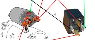
Diagnostics
The first stage of repair is to determine where the breakdown occurred - in the power circuit or the unit itself. This is done simply:
- We immobilize the car with the handbrake, set the gearbox to “neutral”;
- Open the hood. From the thermostat side we find the starter;
- On the solenoid relay we find power contacts (two studs with nuts to which the wiring fits);
- We take a screwdriver with an insulated handle and close the contacts with each other;
If after a short circuit the electric motor starts to turn, the fault should be sought in the solenoid relay and its power supply circuit. If, after the described procedure, the electric motor does not start or will work, but without developing speed, or when triggered, extraneous sounds will occur, the unit will have to be removed from the car.
Operating principle, design and characteristics of fuses
The principle of operation of fuse links is deciphered by their name. Fuses are made of low-fusible conductors that can withstand a certain amperage. Depending on the purpose and voltage of the circuit being served, fuses are divided according to the current strength they can withstand. Typically, VAZ 2114 uses inserts from 5 to 30 Amperes.
Purpose of fuses
The main purpose of the fuse is to protect devices and equipment from overloads and short circuits. If the maximum limit is exceeded (short circuit inside the wiring circuit), the part is destroyed, which leads to an open line. Consequently, the part remains undamaged.
Common faults
Among the frequent calls to the service station are:
- wiring burnout;
- water entering the contacts and, as a result, closing them;
- damage to wires;
- malfunctions of electronic units.
With rare exceptions, the fuse box itself breaks down.
Checking and replacing fuses and block
To check the fuse for serviceability, remove it from the socket and visually inspect it. If the part is intact, there will be no soot or traces of oxidation on it. Direct replacement is carried out using the pliers included in the kit. It is strictly forbidden to pull out the inserts by loosening them - you can break the legs.
Repairing the block is getting more complicated. Here you will need to perform the following sequence of actions:
- open the mounting panel cover;
- find and unscrew the 4 mounting screws;
- Carefully lift the module and disconnect the terminal blocks.
It is important to exercise extreme caution when performing the procedure - the part can be easily damaged