Toyota is known for its high-tech solutions, which can be cited as an example of engineering art. One such example is the dynamic valve timing system VVT-i or Variable Valve Timing with intelligence. Thanks to its work, Toyota cars can boast outstanding performance in terms of power, efficiency, and respect for the environment. Let's take a look at how VVT-i works and why it is so effective.
Toyota is known for its high-tech solutions, which can be cited as an example of engineering art. One such example is the dynamic valve timing system VVT-i or Variable Valve Timing with intelligence. Thanks to its work, Toyota cars can boast outstanding performance in terms of power, efficiency, and respect for the environment. Let's take a look at how VVT-i works and why it is so effective.
The VVT-i (Variable Valve Timing intelligent) system allows you to smoothly change the valve timing in accordance with engine operating conditions. This is achieved by rotating the intake camshaft relative to the exhaust valve shaft in the range of 40-60° (according to the crankshaft rotation angle). As a result, the moment when the intake valves begin to open and the amount of “overlap” time (that is, the time when the exhaust valve is not yet closed, but the intake valve is already open) changes.
The VVT-i (Variable Valve Timing intelligent) system allows you to smoothly change the valve timing in accordance with engine operating conditions. This is achieved by rotating the intake camshaft relative to the exhaust valve shaft in the range of 40-60° (according to the crankshaft rotation angle). As a result, the moment when the intake valves begin to open and the amount of “overlap” time (that is, the time when the exhaust valve is not yet closed, but the intake valve is already open) changes.
1. Design
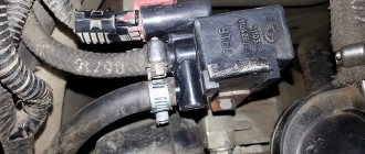
VVT-i is controlled using the VVT-i valve (OCV - Oil Control Valve). Based on a signal from the control unit, the electromagnet moves the main spool through the plunger, bypassing the oil in one direction or another. When the engine is stopped, the spool is moved by a spring so that the maximum delay angle is established.
2. Operation
To rotate the camshaft, oil under pressure is directed using a spool to one side of the rotor petals, while at the same time the cavity on the other side of the petal opens to drain. After the control unit determines that the camshaft has reached the required position, both channels to the pulley are closed and it is held in a fixed position.
Toyota VVT-i system, we understand what it is and what it is for. Time to delve into her insides.
Development of VVT-i technology: what else have the Japanese come up with?
There are other varieties of this technology. So, for example, Dual VVT-i controls the operation of not only the intake camshaft, but also the exhaust camshaft.
This made it possible to achieve even higher engine parameters. Further development of the idea was called VVT-iE.
Here, Toyota engineers have completely abandoned the hydraulic method of controlling the camshaft position, which had a number of disadvantages, because in order to rotate the shaft it was necessary for the oil pressure to rise to a certain level.
This drawback was eliminated thanks to electric motors - now they turn the shafts. Just like that.
Thank you for your attention, now you yourself can answer anyone’s question “VVT-i Toyota, what is it and how does it work.”
Don't forget to subscribe to our blog and see you next time!
The ECM controls oil flow in the VVTI clutch chambers using a solenoid based on signals from the camshaft position sensors. When the engine is stopped, the valve spool is moved by a spring to its maximum tilt angle.
Drive timing (UR series). 1 - VVT-iE engine, 2 - VVT-i control solenoid, 3 - crankshaft position sensor, 4 - camshaft position sensor (intake), 5 - camshaft position sensor (exhaust), 6 - water temperature sensor, 7 - camshaft position sensor
VVTI drive. 1 - engine, 2 - cover (stator gear), 3 - rotor, 4 - driven gear, 5 - spiral plate, 6 - levers, 7 - support, 8 - housing (sprocket), 9 - intake camshaft.
The main timing chain drives the intake camshaft, and then a short connecting chain drives the drive camshaft. The VVTI drive consists of a linkage mechanism and a cycloidal gearbox. The linkage consists of a housing (connected to the timing sprocket), a holder (connected to the camshaft) and a spiral plate and levers connecting them.
The VVTI cycloidal clutch gearbox consists of a cover (with the stator gearbox), a rotor (connected to the electric motor) and a driven gear (which has 1 tooth more than the stator gear) connected to the rotor. When the engine crankshaft rotation increases by 1000 rpm, the driven gear moves by 1 tooth.
The spiral plate connected to the driven gear is driven through a gearbox. The levers transmit the rotation of the spiral plate to the holder, camshaft and VVTI clutch.
The VVTI system consists of a brushless DC motor, an EDU control unit and a Hall sensor. The EDU serves as an intermediary between the ECM and the electric motor, controlling the speed and direction of rotation.
VVTI motor. 1 — electric control unit, 2 — electric motor, 3 — Hall sensor.
Valve timing adjustment is based on the speed difference between the engine and the camshaft. In hold mode, the engine and camshaft speeds are equal. In advance mode, the engine rotates faster than the camshaft. In deceleration mode, on the contrary, it is slower or in the opposite direction.
Engine operating modes.
The ECM signal causes the VVTI clutch motor to rotate faster than the camshaft. The spiral plate rotates clockwise through a gearbox. Levers inserted into spiral grooves move to the central axis of the camshaft and rotate it with acceleration relative to the crankshaft.
The ECM signal causes the engine to rotate lower than the camshaft. The spiral plate rotates counterclockwise through a gearbox. Levers inserted into spiral grooves move away from the central axis of the camshaft and rotate the camshaft relative to the crankshaft at a slower rate.
After reaching the set torque, the engine crankshaft rotates at the same speed as the camshaft. The lever mechanism is fixed and holds the valve timing.
The VVTI clutch with vane rotor is installed on the exhaust camshaft. When the engine is stopped, a locking pin keeps the rotor pushed all the way forward for normal starting. An auxiliary spring mechanism serves to return the rotor and ensure reliable operation of the lock after the engine is turned off.
VVTI drive. 1 - housing, 2 - rotor, 3 - locking pin, 4 - sprocket, 5 - camshaft, 6 - auxiliary spring. a - stop, b - work, c - oil pressure.
The ECM controls oil flow in the VVTI clutch chambers using a solenoid based on signals from the camshaft position sensors. When the engine is stopped, the valve spool is moved by a spring to its maximum tilt angle.
a - spring, b - bushing, c - valve spool, d - to the drive (front chamber), e - to the drive (return chamber), f - drain, g - oil pressure, h - coil, j - piston.
The ECM moves the solenoid to the advance position and moves the control valve spool. Engine oil under pressure is supplied to the rotor in the advance chamber, turning it together with the camshaft in the advance direction.
The ECM also switches the solenoid to the retard position and moves the control valve spool in the opposite direction. Engine oil is supplied under pressure to the rotor into the deceleration chamber, turning it along with the camshaft in the deceleration direction.
The ECM calculates the target angle based on engine operating parameters and, once the target position is reached, switches the control valve to the neutral position until the next change in environmental conditions, keeping oil in the circuit.
Quite often, problems and malfunctions of the VVTI coupling are associated with contamination of its components. An effective remedy to help solve this problem is flushing the BG 109 oil system. In 8 out of 10 cases, it helps eliminate the problem without disassembling it.
Another type of variable valve timing system is based on the use of cams of various shapes, which achieves a stepwise change in the opening duration and valve lift height. Well-known such systems are:
The variable valve timing system (common international name Variable Valve Timing , VVT ) is designed to regulate the operating parameters of the gas distribution mechanism depending on engine operating modes. The use of this system provides increased engine power and torque, fuel efficiency and reduced harmful emissions.
The adjustable operating parameters of the gas distribution mechanism include:
- moment of opening (closing) of valves;
- duration of valve opening;
- valve lift height.
Together, these parameters make up the valve timing - the duration of the intake and exhaust strokes, expressed by the angle of rotation of the crankshaft relative to the “dead” points. The valve timing is determined by the shape of the camshaft cam acting on the valve.
Different engine operating modes require different valve timing values. Thus, at low engine speeds, the valve timing should have a minimum duration (“narrow” phases). At high speeds, on the contrary, the valve timing should be as wide as possible and at the same time ensure overlap of the intake and exhaust strokes (natural exhaust gas recirculation).
The camshaft cam has a specific shape and cannot simultaneously provide narrow and wide valve timing. In practice, cam shape is a compromise between high torque at low rpm and high power at high crankshaft speed. This contradiction is precisely resolved by the variable valve timing system.
Depending on the adjustable operating parameters of the gas distribution mechanism, the following methods of variable valve timing are distinguished:
- camshaft rotation;
- the use of cams with different profiles;
- changing valve lift height.
The most common are variable valve timing systems that use a camshaft rotation:
- VANOS ( Double VANOS ) from BMW;
- VVT-i (Dual VVT-i), Variable Valve Timing with intelligence from Toyota;
- VVT , Variable Valve Timing from Volkswagen ;
- VTC , Honda's Variable Timing Control;
- CVVT , Continuous Variable Valve Timing from Hyundai, Kia, Volvo, General Motors;
- VCP , Variable Cam Phases from Renault.
The operating principle of these systems is based on the rotation of the camshaft in the direction of rotation, which achieves early opening of the valves compared to the initial position.
The design of a variable valve timing system of this type includes a hydraulically controlled clutch and a control system for this clutch.
In most cases, a hydraulically controlled clutch is installed on the intake camshaft. To expand the control parameters in certain designs, couplings are installed on the intake and exhaust camshafts.
The variable valve timing system typically operates in the following modes:
- idle speed (minimum crankshaft speed);
- maximum power;
- maximum torque.
Another type of variable valve timing system is based on the use of cams of various shapes, which achieves a stepwise change in the opening duration and valve lift height. Well-known such systems are:
- VTEC , Variable Valve Timing and Lift Electronic Control from Honda;
- VVTL-i , Variable Valve Timing and Lift with intelligence from Toyota;
- MIVEC , Mitsubishi Innovative Valve timing Electronic Control from Mitsubishi;
- Valvelift System from Audi.
These systems have basically the same design and operating principle, with the exception of the Valvelift System. For example, one of the most famous VTEC systems includes a set of cams of various profiles and a control system.
The camshaft has two small and one large cams. The small cams are connected through corresponding rocker arms to a pair of intake valves. The large cam moves the free rocker arm.
Another modification of the VTEC system has three control modes, determined by the operation of one small cam (opening one intake valve, low engine speed), two small cams (opening two intake valves, medium speed), and a large cam (high speed).
Honda's modern variable valve timing system is the I-VTEC system, which combines VTEC and VTC systems. This combination significantly expands the engine control parameters.
The most advanced type of variable valve timing system from a design point of view is based on adjusting the valve lift height. This system allows you to eliminate the throttle valve in most engine operating modes. The pioneer in this area is BMW and its Valvetronic . A similar principle is used in other systems:
- Valvematic from Toyota;
- VEL , Variable Valve Event and Lift System;
- MultiAir from Fiat;
- VTI , Variable Valve and Timing Injection from Peugeot.
The Valvetronic system is installed only on the intake valves.
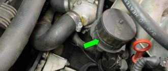
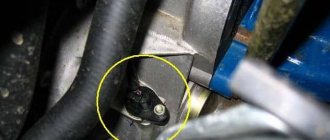
Today we’ll talk about the device of this type of valve as VVT-i, it is also called a phase sensor.
Today we’ll talk about the device of this type of valve as VVT-i, it is also called a phase sensor.
But first, let's understand its structure, operating principle and operating nuances. The VVT-i valve takes its place in modern cars. And it is responsible for such a phenomenon as changing the timing of gas intake/exhaust.
In pursuit of the goal of “boosting” engine power to maximum, car owners often install a clutch on the intake camshaft. The phase sensor (which is a valve) in this case acts as a control system for this clutch, namely, it is responsible for the amount of oil in the system.
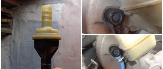
The VVT-i valve is:
- working part body
- the outer part of the housing (a solenoid is built into it, which controls the movement of the phase sensor)
- sealing rubber (ring)
- electrical connector
Globally, the valve data does not differ from each other. Certain small nuances in its operation depend on the brand.
The main factors that cause the VVT-i valve to fail are:
- wear and tear over service life
- oil contamination
- damage to the power connector (mechanical)
The signal that the phase sensor requires attention is error p0016. In most cases, it is replacement rather than repair that is required.
Cleaning can be done using carburetor cleaning fluids. To completely clean the system, remove the filter. This element is located under the valve - it is a plug in which there is a hole for a hexagon. The filter also needs to be cleaned with this liquid. After all the operations, all that remains is to assemble everything in the reverse order, and then install the generator belt without resting against the valve itself.
How the system works
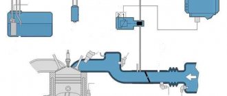
The operating principle of the VVT-I system promotes a smooth change in valve timing, depending on the operating conditions of the power unit.
This occurs due to the rotation of the intake camshaft in relation to the drive gear in the range from 40 to 60 degrees. The VVT drive, equipped with a vane rotor, is mounted on the intake shaft. If the engine is at rest, then normal starting is ensured by a special clamp that holds the camshaft in the maximum delay position.
1 — VVT-i control valve, 2 — camshaft position sensor, 3 — coolant temperature sensor, 4 — crankshaft position sensor, 5 — VVT drive
Due to the electromagnetic valve controlled by the electronic unit, the oil supply in the delay and advance cavities of the VVT drive is adjusted. Information on the dosage of supplied oil is taken from the signals of the camshaft position sensor. The maximum delay angle when the engine is off is created thanks to the spool, which is moved by a special spring.
Commands to the solenoid valve come from the engine control unit. Depending on the specific motor mode, the following may occur:
the valve goes into advanced mode and moves the spool of the control mechanism. In this case, the oil flow is directed to the rotor from the side of the advance cavity, turning the camshaft;
Oil movement inside the VVT-I valve and coupling
- the valve goes into delay mode and moves the spool of the control mechanism. In this case, the oil flow is directed to the rotor from the side of the delay cavity, which leads to rotation of the camshaft in the same direction;
- holding the valve in neutral position without changes.
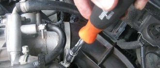
Do-it-yourself valve repair
First, remove the generator control bar. Then remove the hood lock fasteners. This will give access to the generator axle bolt. Next, unscrew the bolt that holds the valve itself and remove it. Then remove the filter. If the last element and valve are dirty, then these parts are cleaned. Repair consists of inspection and lubrication. You can also replace the O-ring. More serious repairs are not possible. If a part doesn't work, it's easier and cheaper to replace it with a new one.
There are seven operating modes of a car engine in total and here is a list of them:
Vvt-i device
At the moment when the car engine is not functioning, the spool moves with the help of a spring so as to position the maximum delay angle.
Installed VVTI valve
In total, there are seven modes of operation of a car engine and here is a list of them:
- Driving at idle speed;
- Movement at low load;
- Movement with medium load;
- Moving with a high load and low speed;
- Moving with a high load and high speed;
- Driving with low coolant temperature;
- When starting and stopping the engine.
Self-cleaning procedure for Vvt-i
There are usually many signs associated with dysfunction, so it makes sense to look at those signs first.
So, the main signs of disruption of normal functioning are:
- The car suddenly stalls;
- The vehicle cannot maintain speed;
- The brake pedal becomes noticeably stiff;
- The brake pedal does not pull.
Now we can move on to consider the Vvti purification process. We will carry out Vvti cleansing step by step.
So, the algorithm for Vvti cleansing is:
Self-repair Vvt-i
Quite often there is a need to repair the valve, since simply cleaning it is not always effective.
So, first, let's look at the main signs of the need for repairs:
- The car engine does not hold idle speed;
- Engine brakes;
- It is impossible to move the car at low speeds;
- No brake booster;
- Gear shifts poorly.
Let's look at the main causes of valve failure:
- The coil has broken. In this case, the valve will not be able to respond correctly to the voltage transfer. This violation can be determined by measuring the winding resistance.
- The rod is stuck. The reason for the rod sticking may be the accumulation of dirt in the rod channel or deformation of the rubber band, which is located inside the rod. You can remove dirt from the channels by soaking or soaking.
Valve repair algorithm:
Self-replacement procedure for Vvt-i valve
Often, cleaning and repairing the valve does not give much results and then it becomes necessary to completely replace it. In addition, many car enthusiasts claim that after replacing the valve, the vehicle will perform much better and fuel consumption will drop to approximately ten liters.
Therefore, the question arises: How should the valve be replaced correctly? We will replace the valve step by step.
So, the valve replacement algorithm:
- Remove the vehicle alternator adjusting bar;
- Remove the car hood lock fasteners, thanks to this you can gain access to the axial bolt of the generator;
- Unscrew the bolt that secures the valve;
- We take out the old valve;
- We install a new valve in place of the old one;
- We tighten the bolt securing the valve;
- The valve replacement is complete and all you have to do is reassemble everything in reverse order.
- valve – damage is caused by the use of poor quality oil or mechanical wear;
- the clutch is also picky about the quality of the oil used. The malfunction is accompanied by an extraneous knock. The element itself may have a collapsible or non-collapsible design. In most cases, when installing a collapsible coupling, it is enough to replace the rubber gasket;
Possible causes of valve failure
How to Check the Adsorber Valve on Kalina
There are not so many main reasons for valve malfunctions. There are two that are particularly common. So, the VVTI valve may fail due to breaks in the coil. In this case, the element will not be able to respond correctly to voltage transfers. Diagnosis of the malfunction is easily carried out by checking the resistance measurement of the sensor coil winding.
The second reason why the VVTI (Toyota) valve does not work correctly or does not work at all is jamming in the stem. The cause of such jamming may be simple dirt that has accumulated in the channel over time. It is also possible that the sealing rubber inside the valve is deformed. In this case, restoring the mechanism is very simple - just clean the dirt from there. This can be done by soaking or soaking the element in special liquids.
Incorrect operation of VVT-I
VVT-I problems may be accompanied by the following symptoms:
- periodic manifestation of unstable engine operation, which is accompanied by a prolonged increase in speed. The problem lies in the wedging rod;
- When the transmission is engaged in neutral, the engine speed increases sharply to a value of 3000 to 4000 rpm. In this case, error No. 59 appears. This is the only sign of a malfunction of the VVT-I sensor, which is accompanied by an error;
- increase in fuel consumption. Provided that elements such as spark plugs, throttle assembly, lambda sensor and so on are checked;
- loss of traction of the power unit when operating at low speeds;
- manifestation of floating speed when the gear is engaged, when in traffic jams. You will first need to check other components of the fuel system;
- when starting from a standstill, there is a sharp increase in the speed of the power unit, followed by a decrease to zero. As a result, the engine stalls;
- an uneven set of revolutions when accelerating a car, accompanied by sharp jerks.
The listed problems may arise due to failure of the following VVT-I elements:
- valve – damage is caused by the use of poor quality oil or mechanical wear;
- the clutch is also picky about the quality of the oil used. The malfunction is accompanied by an extraneous knock. The element itself may have a collapsible or non-collapsible design. In most cases, when installing a collapsible coupling, it is enough to replace the rubber gasket;
- temperature sensor - the correct functioning of the system directly depends on the temperature of the power unit. If the sensor breaks down, problems with VVT-I operation occur.
Misconceptions
The operation of the VVT-I system raises many questions that give rise to various misconceptions. Among them are:
- VVT-I operates exclusively at high speeds, so idle speed problems are not related to it in any way. In fact, the system is involved in the operation of the engine at idle speed. At high speeds, valve opening should be observed, and at idle, the camshaft rotation angle becomes maximum. If there is a malfunction in the mechanism rod, the specified angle is violated, which is accompanied by floating engine idle speed;
- the engine can safely operate even with a faulty VVT-I valve, without loss of power. This opinion is considered not entirely correct. If the regulator is turned off, the motor will indeed operate practically unchanged. But if the device is connected and faulty, problems will occur in the functioning of the power unit.
- Checking the VVT-I valve on the 1ZZ-FE engine is carried out using the following method: turn off the supply loop; the engine starts; 12 V power is supplied to the sensor. If the operations performed lead to the power unit stopping, then VVT-I is working. In practice, this technique only works when the valve is obviously faulty. If wedging is observed, the result may be contradictory.
- The faulty part can be inspected. This statement is considered erroneous. This is due to the fact that there are both collapsible and non-dismountable devices. The most that can be done is to clean the valve. It is almost impossible to adjust spring compression according to factory requirements;
- You can save money by purchasing a VVT-I sensor from disassembly. This option can of course be used, but the risk of acquiring a worn valve is very high;
- A cheap analog sensor works no worse than the original. Here everything depends on the quality of the analogue; as a rule, when installing it, weak traction of the power unit is observed at low speeds.
In order to be sure that the VVT-I valve is faulty, you will need to try installing a known-good sensor and test the performance of the motor.
Cleaning
In order to check the cleanliness of the valve on the 1ZZ-FE engine, you must do the following:
Repair
The following factors may cause repair of the VVT-I valve:
- a break in the coil, which is accompanied by the absence of any reaction when voltage is applied to the sensor;
- Mechanical jamming of the rod is observed due to dirt getting into the internal cavity of the device or wear of the internal rubber gasket.
Before carrying out repair work, you will need to purchase the appropriate repair kit. Repairs can only be made if the sensor has a dismountable design. For the 1ZZ Toyota engine, the lubrication system valve 15330-22030 is used. Next, remove the VVT-I sensor, the dismantling process is described in the previous paragraph, and proceed to the following steps:
The principle of operation of the system is to change the position of the camshafts relative to the crankshaft pulley.
Lifehack Blog VVT-i Diagnostics
How to check the solenoid valve of a gas boiler
This entry is a continuation of the topic about disassembling and troubleshooting the VVT-i controller (Nonsense Blog. VVT-i coupling). Or rather, this is most likely prehistory. Since you first need to diagnose a breakdown, and then defect something, disassemble and repair it. At one time, I quite often had to answer questions regarding the performance of VVTL or VVT, about errors P1349, P1693, etc.
Suddenly, an error message came on telling you to throw out the engine (Check Engine), but nothing special happens, the car just drove and drove, only over time comes the realization that it has become more fuel-consuming and less responsive at medium speeds. Having considered the error, Let's say that you received one of the most common VVT errors, this is P1349 or P1346. If P1349 directly hints at a defect in the VVT mechanism, then P1346 signals an error associated with the camshaft position sensor, but one way or another, it may indicate irregularities in the operation of VVT, for example incorrect Timing phases.
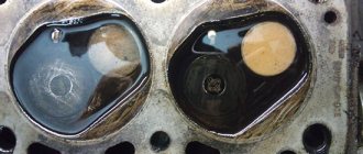
Diagnostics. First of all, it is necessary to determine which node the brain makes for us. Consider the main 3 mechanical malfunctions1. VVT valve filter
A banal mesh, but it can be a little dirty)
and thereby lead to disruption of the VVT2 system. OCV VALVE, aka VVT Solenoid, aka VVT valve
A rather delicate device, which is a several-port solenoid that transfers oil into one channel or another (to advance or retard the shaft).
Many people assume that it works and is controlled according to an algorithm - “closed” - “held pressure” Not quite so. The VVT valve is controlled by the ECU via PWM, and this is done continuously. This is how the valve works in the engine
Although the valve design is commonplace, when working in an aggressive environment, weak points often suffer, for example, deformation of the sealing ring, which leads to sticking of the rod, or weakening of the return spring, which does not return the valve to its original position. And so... we diagnose. We take 2 wires, preferably with connectors
We connect to the valve and to the battery, do not connect the second pole yet
We close the second wire to positive (without fanaticism, short circuits can burn the winding) and listen
It clicks, goes back and forth... If it doesn’t click... then, in principle, everything is clear. However, a small correction. This valve may work fine when you remove it from the engine, but not work in the engine itself. This is due to the fact that the valve can only stick when warm. Therefore, before this test, warm up the engine to operating temperature...
3. VVT couplingAcceptable valve is working. The next Test is the activation of the VVT controller. This can also be done without a dealer scanner. Start the engine and apply voltage to the VVT valve
If there are no changes in the operation of the engine... Then the VVT controller is more likely dead than alive) What should have happened? By applying voltage, you open a channel that brings the VVT Clutch to the position corresponding to the maximum overlap of the intake and exhaust valves.
At idle, the engine cannot operate with such overlap, as the breakthrough of exhaust gases into the intake increases. And the engine stalls.
If the oil pressure in the system is sufficient... then mechanically there is simply nothing left to break.
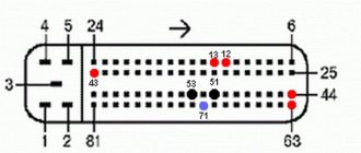
Wiring, electronics, timing timing and camshaft position sensor. With P1346, you should check whether the timing marks are set correctly, as well as the functionality of the sensor, the integrity of the wiring, whether there is oxidation in the connectors... Well, the worst and most difficult to diagnose is the ECU...
CVVT system design
CVVT (Continuous Variable Valve Timing) is a system for continuously adjusting engine valve timing, ensuring more efficient filling of the cylinders with fresh charge. This is achieved by shifting the opening and closing timing of the intake valve.
Vehicle CVVT system
The system includes a hydraulic circuit consisting of:
- Control valve-solenoid.
- VVT system filter.
- Actuator (CVVT hydraulic coupling).
All system components are installed in the engine cylinder head. The VVT system filter must be periodically cleaned or replaced.
CVVT hydraulic couplings can be installed on both the intake and both shafts of the internal combustion engine.
If phase shifters are installed on the intake and exhaust camshafts, this gas distribution system will be called DVVT (Dual Variable Valve Timing).
Additional elements of the system also include sensors:
- Position and speed of the crankshaft.
- Camshaft positions.
These elements send a signal to the engine ECU (control unit). The latter processes the information and generates a signal to the solenoid valve that regulates the oil supply to the CVVT clutch.
CVVT coupling
The hydraulic coupling (phase shifter) has an asterisk on the body. It is driven by a timing belt or chain. The camshaft is rigidly connected to the phase shifter rotor. Oil chambers are located between the rotor and the clutch housing. Due to the oil pressure created by the oil pump, it is possible for the rotor and housing to move between each other.
The coupling consists of:
- rotor;
- stator;
- locking pin.
The locking pin is necessary for the operation of the phase shifters in emergency mode. For example, when the oil pressure drops. It is pushed forward, which allows the housing and rotor of the hydraulic coupling to be closed in the middle position.
VVT Clutch and Valve
How does the VVT solenoid control valve work?
This mechanism serves to regulate the oil supply to delay and advance the opening of valves. The device consists of the following elements:
- Plunger.
- Connector.
- Spring.
- Frame.
- Spool.
- Holes for oil supply, supply and drainage.
- Winding.
The engine ECU generates a signal, after which the electromagnet moves the spool through the plunger. This allows the oil to flow in different directions.
“Smooth operation” is applied here to the intake valves, and there is no camshaft at all. It is preserved only on the exhaust part, but it also has an effect on the intake (I’m probably confused, but I’ll try to explain).
Japanese-style valve timing control
Let's start with decoding.
The abbreviation VVT-i sounds in the original language as Variable Valve Timing intelligent, which we translate as intelligent change of valve timing.
This technology was first introduced to the market by Toyota ten years ago, in 1996. All automakers and brands have similar systems, which indicates their usefulness. They are called, however, all differently, confusing ordinary motorists.
What did VVT-i bring to the engine industry? First of all, an increase in power, uniform throughout the entire speed range. Motors have become more economical and therefore more efficient.
Control of valve timing or control of the moment of raising and lowering the valves occurs by turning the camshaft to the desired angle.
Let's look at how this is technically implemented below.
Soft start or Fiat MultiAir, BMW Valvetronic, Nissan VVEL, Toyota Valvematic
If you want smoothness, please, and here the first company in development was (drum roll) – FIAT. Who would have thought, they were the first to create the MultiAir system, it is even more complex, but more accurate.
“Smooth operation” is applied here to the intake valves, and there is no camshaft at all. It is preserved only on the exhaust part, but it also has an effect on the intake (I’m probably confused, but I’ll try to explain).
This allows for smooth activation depending on engine speed. Now many manufacturers also have such developments, such as BMW (Valvetronic), Nissan (VVEL), Toyota (Valvematic). But these systems are not completely ideal, what’s wrong again? Actually, here again there is a timing drive (which takes up about 5% of the power), there is a camshaft and a throttle valve, this again takes a lot of energy, and accordingly steals efficiency, I wish I could give them up.
Sources
https://avtonov.com/vvt-i-%D1%87%D1%82%D0%BE-%D1%8D%D1%82%D0%BE-%D0%B7%D0%B0-%D1% 81%D0%B8%D1%81%D1%82%D0%B5%D0%BC%D0%B0-%D0%BD%D0%B0-toyota/ https://autodata.ru/article/all/sistema_toyota_vvt_i / https://auto-ru.ru/vvti-toyota-chto-eto.html https://bg-moskva.ru/printsip-raboty-mufty-vvti https://systemsauto.ru/vpusk/vvt.html https://car.ru/remont-auto-svoimi-rukami/dvigatel-i-ego-komponenty/28279-klapan-vvt-i-kak-ustroen-i-printsip-deystviya-datchika-faz/ https:// principraboty.ru/vvti-princip-raboty/ https://autodont.ru/grm/vvti https://toyota-camry-corolla.ru/dvigateli/klapan-vvt-i/ https://techautoport.ru/dvigatel /mehanicheskaya-chast/sistema-cvvt.html https://7gear.ru/tuning/vvti.html