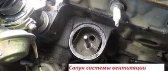
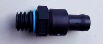
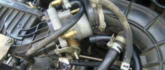
—Before reading the post and deciding to implement it, think about whether you need it. If there are problems described in the recording, contact those who have already installed the valves, ask whether they work or not.
—Due to the weak design and small engine volume, everyone who installed a General Motors valve 94580183 in a small circuit without a pressure reducing valve in a large circuit, monitor the oil level and jerking from the engine. — If oil burns, strong jerking and vibrations appear, remove the General Motors valve 94580183. Instead, it is better to choose the PSV-PCV valve 2674021314. Sankei KP125 or 2674032804 for eight-valve engines. — You can also choose the PSV valve yourself. The main criterion when choosing a valve is the volume and power of the engine on which it is installed, which should be no less, but preferably a little more.
Next, carry out the following work: - check the entire intake system for leaks. — crankcase ventilation large and small circuits, tubes pressed into the valve cover, oil dipstick seal, breather. — intake control hoses for leaks on engines with variable intake length. — update the ECU firmware to the latest factory firmware. — replace the vacuum booster valve with MW400017 MITSUBISHI, if you hear a rattling sound when you press the brake pedal, or you have no news and crap, they have it like that from the factory. - check the efficiency of the adsorber valve, before starting the engine, turn off its pipe to prevent it from working - check the timing marks - on cars with E-GAS, check the correct operation of the clutch sensor, it may not work and not give errors.
Some more advice, I will add to it: - never install filters or oil sumps in the low ventilation circuit if there is a PCV valve. Never. - make the small circuit line as short as possible, so that on the 16 valve the valve lies above the throttle, and on the 8 valve the valve is above the receiver fitting or valve cover. — if you operate the machine in areas with a cold climate, you can insulate the small circuit line with a valve. — in case of maintenance, do not blow with compressed air, do not shake the valve. Simply rinse with carb cleaner and dry.
Theory
— During engine operation, gases break through from the cylinder cavity above the piston into the crankcase.
These gases, called crankcase gases, consist of approximately equal parts of the combustible mixture and products of complete and partial combustion. As a result, crankcase gases contain fuel vapors, carbon oxides (including CO), sulfur, nitrogen, products of partial oxidation of fuel hydrocarbons, water vapor. Many of these components actively affect the oil, as a result of which it oxidizes, resinous and varnish-like substances, acids, salts of acids, etc. are formed in it. As a result, the oil loses its properties or, as they say, ages. Active acids, forming an emulsion with oil, enter the rubbing surfaces and cause corrosion. — In order to minimize the influence of crankcase gases and reduce the intensity of the oil aging process, it is necessary to remove them from the crankcase space. — The process of removing gases is called crankcase ventilation
, and the set of devices that ensure this process is called
a ventilation system
. — Ventilation also serves to maintain pressure close to atmospheric in the crankcase space. If the removal of gases is insufficient or absent altogether, the pressure in the crankcase increases sharply due to the constant influx of a new amount of gases. This can cause oil to be squeezed out of the crankshaft seals and other crankcase leaks. Intensive removal of crankcase gases leads to the suction of atmospheric air contaminated with dust and moisture into the crankcase. — Experience shows that oil stability is significantly improved if the crankcase space is purged with a small amount of fresh air. Therefore, there are two types of ventilation systems: exhaust, i.e. without purging the crankcase space with air, and supply and exhaust - with purging. The air entering the crankcase during supply and exhaust ventilation must be cleaned in a separate filter or in an air cleaner of the engine air supply system. — Crankcase gases can be released into the atmosphere or returned to the engine intake tract. Ventilation systems that remove crankcase gases into the atmosphere are called open. Systems with the removal of gases into the intake tract - closed ventilation systems.
1 - Schemes of crankcase ventilation of engines: a) open; b) closed exhaust; c) closed supply and exhaust; d), e). e) - designs of automatic control valves of closed ventilation systems
— Until 1961, the entire automotive industry used an open system with an ejection operating principle in manufactured vehicles, in which an ejection tube running along the entire engine to the lower crankcase pan was used to remove gases from the crankcase. The diagram of the open ventilation system is shown in Fig. 1, a
.
When the car moved, a slight vacuum formed near the edge of tube 1
, which had a good effect on crankcase ventilation.
To prevent direct ejection of oil droplets with crankcase gases, the ejection tube is recessed into chamber 2
.
Air enters the crankcase through the oil filler neck, the cover 3
of which is equipped with a filter pad. The engines of Zaporozhets, Chaika, Ural-375, and MAZ cars have such a ventilation system. — A little later, the results of research conducted by GENERAL MOTORS proved that the main amount of harmful substances formed as a result of incomplete combustion of hydrocarbons is released into the atmosphere through the ejection tube of the ventilation system. As a result of this discovery, starting in 1961, all cars sold in the state of California (America) were required to be equipped with a closed exhaust system, and since 1962, this requirement began to apply throughout the United States.
- In Fig. 1, b
shows a diagram of a closed exhaust ventilation system.
Gases are sucked out here from under the valve mechanism cover through an ejection tube 2
, led into the inlet neck of the air cleaner.
Before the crankcase gases exit from under the valve mechanism cover, an oil deflector curtain 1
.
Mixing with the air flow, crankcase gases pass through the filter pack 3
of the air cleaner and are freed from oil droplets, condensed vapors and other impurities (engines MZMA-408, ZMZ-21 and up) If the air cleaner has a dry paper filter element, then the crankcase gases must be vented to intake tract to the area behind the air cleaner.
In this case, an independent filter element is installed in the path of crankcase gases. Due to the simplicity of their design, these systems are widely used, especially on foreign engines. - In Fig.
1, c shows a diagram of a closed supply and exhaust ventilation system, where crankcase gases are removed through
tube 3
into the throttle space of the intake
tract 4
.
Consequently, crankcase gases do not pass through the metering elements of the power supply system and do not pollute them, but they affect the operation of the carburetor 5
, reducing the vacuum in its channels.
To minimize the impact of such a ventilation system on mixture formation, it is equipped with a valve device 2
that regulates the intensity of crankcase gas removal.
At the outlet of gases from the crankcase space, an oil-collecting packing or oil deflector 1 is installed. Air for purging the crankcase space enters through the oil filler neck 6
, equipped with a filter element (ZIL-130 engine and a number of American engines).
The presence of a valve device complicates the ventilation system and increases the likelihood of system failure. — Valve designs used in ventilation systems made according to the diagram in Fig.
1, in , are shown in
Fig.
1, d, d, f .
— We will consider the operating principle of an automatic fluometer-type valve (floating valve (hereinafter referred to as “PCV valve”)) according to the diagram in Fig.
1, g .
The mushroom-shaped valve with through radial and axial holes in the non-working state is pressed by a spring to the extreme right position and with its heel closes the channel communicating with the crankcase space. When starting and idling the engine, when large vacuums arise in the intake pipe, the valve, overcoming the resistance of the spring, is sucked into the channel communicating with the intake pipe and closes it with its nose, and crankcase gases pass through calibrated holes in the valve itself. As the throttle valve opens, the vacuum in the intake manifold decreases, the valve is pressed away from the seat by a spring and is held in a certain middle position by the flow of gases. -There is also a so-called backfire mode, in which burning gases from the cylinder break into the intake manifold. In this case, the PCV valve is under the influence of pressure, not vacuum, and therefore closes completely, eliminating the possibility of igniting the fuel vapors in the crankcase. — The valve of the ZIL-130 engine ventilation system works similarly, the design of which is shown in Fig.
1, d .
In the non-working position, the automatic valve with its lower conical end closes the channel connecting to the crankcase space. When starting and idling, the valve is sucked up and its needle nose partially blocks the outlet hole in the valve body. At medium and full load modes, the valve lowers and is held approximately in the middle position by the flow. — In addition to floating automatic valves, ventilation systems use controlled diaphragm valves that change the flow area of the ventilation channel depending on the operating mode of the engine. — The design of the diaphragm valve is shown in Fig.
1, e .
(hereinafter referred to as “Reducing valve”) body 4
above
the membrane 1
is connected to the atmosphere through an opening, and the cavity under the membrane is connected to the inlet pipeline.
The diaphragm, loaded by a spring 2
, is connected by a rod to
a hollow spool 3
, which is located in a tube connected to the crankcase space. As the throttle valve closes, the vacuum in the intake manifold and in the lower valve cavity increases. The membrane bends down and the spool begins to close the hole in the tube, thereby reducing the intensity of gas suction from the crankcase space. Diaphragm valves are quite effective and are widely used in automobile engines of foreign and domestic manufacturers. Modern devices for crankcase ventilation of engines are an independent system that has a significant impact on the operation of other engine systems. Source: Raikov I.Ya., Rytvinsky G.N. Internal combustion engines, 1971: auto.today/bok/2211-venti…-kartera-dvigatelya1.html; avtoaziya.ru/avtotekhnolo…i-kartera-dvigatelya.html
Components of the ventilation system
The crankcase ventilation configuration depends on the type of internal combustion engine installed on the vehicle. Despite this, the system includes the following elements:
- air pipe;
- a ventilation valve that performs the function of suctioning gases. The intensity of its functioning increases with increasing vacuum force inside the intake manifold;
- oil separator
Crankcase ventilation can be roughly divided into 2 large functional parts. These include:
- Small branch. Performs the function of selecting crankcase gases that accumulate under the valve cover.
- Big branch. Exhaust gases are removed from under the cover.
Both branches function harmoniously and are completely dependent on each other.
Possible heater malfunctions
Your stove is not working or is not heating well. Look for the cause of the problem. The fan does not work or the heater radiator is leaking - obvious breakdowns that occur at any time.
Stove control unit:
- The engine was warmed up, but warm air did not enter the cabin.
- The damper drive cables may have come off. The only solution is to remove the console.
Dampers. Partially open or close. The rubber seal has come off in the air duct or foreign objects have gotten into it.
Antifreeze circulation. Start the engine and check the level in the expansion tank, and also check for any disturbances in the normal flow of antifreeze. Possible reasons:
- Pump. Cannot be repaired, only replaced.
- The cooling system is clogged. Clean or rinse.
Checking the thermostat. Warm up the engine to 75°C. If the upper pipe is cold, then the thermostat does not work correctly and does not allow coolant to move in a large circle. Replace the device.
Airlock. Remove the plug from the vehicle's engine cooling system.
Temperature sensor. Constantly blowing cold or hot air. If cleaning the contacts does not help, then replace the non-working temperature sensor.
Air filter. If the air flow is weak and there is no desired temperature, then replace the filter. Be sure to check the heater resistor, which controls the rotation of the fan and is located under the glove compartment.
Electric fan. The device does not turn on regardless of the selected mode. Check the fuse that controls operation. If the fan is turned on and its operation is accompanied by strange sounds, clean or replace it.
Dampers. It is difficult to determine the breakdown unless you replace the dampers themselves.
The cause of a heater malfunction may be a depressurization of the car's engine cooling system. The types of breakdowns described above cause malfunctions in the operation of the Lada Kalina car's stove. Such breakdowns do not require special knowledge; they are easy to understand and repair.
Principle of operation
When a mixture of fuel and air is burned, a sharp and strong increase in its volume occurs. This creates high pressure in the internal combustion chamber, which forces the piston to its bottom dead center. The movement of the piston drives the engine crankshaft.
Some of the gases formed in this case, penetrating through the gap between the rings and the cylindrical mirror, enters the cavity under the crankcase cover. Here they mix with oil vapors, which leads to the formation of pressure.
The pressure has an aggressive effect on the crankshaft O-rings, as well as on the gasket located between the pan cover and the oil dipstick channel.
The expansion stroke is periodically repeated in each of the cylinders. This leads to the injection of a repeated portion of gases. If the crankcase ventilation is insufficient, exhaust gases accumulate and the crankshaft seals are gradually squeezed out.
If you do not clean the crankcase ventilation system, it is possible that gases will push out the oil dipstick and oil will leak out of the crankcase. In addition, the following elements accumulate in the crankcase:
- a small part of the fuel that did not have time to burn;
- small soot particles;
- moisture.
All elements are mixed with engine oil that has fallen into the pan. As a result, over time the oil oxidizes, clogging it and reducing its service life.
Stories from our readers
“Fucking basin. "
Hi all! My name is Mikhail, now I’ll tell you a story about how I managed to exchange my two-wheeler for a 2010 Camry. It all started with the fact that I began to be wildly irritated by the breakdowns of the two-wheeler, it seemed like nothing serious was broken, but damn it, there were so many little things that really started to irritate me. This is where the idea arose that it was time to change the car to a foreign car. The choice fell on the melting Camry of the tenth years.
- 145 rub.
- Description
- Characteristics
- Reviews (0)
- Question answer
The process of removing crankcase gases
The removal of exhaust crankcase gases has some differences between carburetor and injection type engines. Regardless of this, the entire procedure follows a standard scheme:
- Exhaust gases are sucked from the engine crankcase.
- In the oil separator, gases are purified from impurities of oil vapors and other combustion products.
- Purified gases move to the intake manifold through the air pipes.
- Crankcase gases mix with the fuel mixture and burn in the engine cylinders.
It is possible that a small amount of gas is getting into the oil pan. As a result, the process of selecting crankcase gases is disrupted.
Possible system malfunctions
Unfortunately, in the first stages it is almost impossible to identify problems associated with clogging of the SWR. They can only be identified after the system is almost completely clogged.
This could cause the engine to malfunction or force oil out of the gaskets between the oil pan and the valve cover. In this case, thorough cleaning of the crankcase ventilation is necessary.
Even when using very high quality piston rings, it is impossible to ensure maximum sealing of the piston. This will invariably lead to gradual clogging of the crankcase space with combustion products of the fuel mixture, as well as its slight compression.
In order to ensure the normal functioning of the crankcase ventilation system, it is necessary to ensure an air supply to the crankcase space. Otherwise, a large vacuum will form in the crankcase.
This leads to loss of valve mobility and their jamming in a certain position. Crankcase gases include particles of soot and carbon deposits. If the engine is in poor condition, a large number of particles accumulate. They gradually accumulate not only on the valve itself, but also on the calibration holes and ventilation pipes.
In winter, when steam moves through the crankcase ventilation system, it can gradually accumulate in its narrow places, turning into ice. This process is known as freezing. If a large amount of ice accumulates, the dipstick may squeeze or force oil out from under the crankcase cover.
If the combustion products of the fuel mixture can accumulate over a long period, the freezing process develops very rapidly. To avoid the development of this problem, engine developers use heating systems in the ventilation system.
The operating instructions for the vehicle must indicate that it is necessary to periodically clean the crankcase gases, which should be carried out in parallel with changing the engine oil.
Additional features
Of course, initially, created to create environmentally friendly engine operation, the Lada Granta adsorber, the price of which is insignificant, was underestimated. Manufacturers tried with all sorts of tricks to circumvent this newfangled trend, but the law obliged all car manufacturers who did not comply with this innovation to pay heavy fines.
Although AvtoVAZ has never been known for its large exports, it was forced to take measures to install an adsorber, since it has a small, but still a sales market. Today, the adsorber is installed on the Lada Granta without fail, since world research has revealed the following capabilities of this component:
– reduction in gasoline consumption
A similar result is achieved because the adsorber valve allows gases to be driven back into the gas tank, from where they enter the engine, which, when warm, is capable of processing them. If this device is missing, or the canister valve itself does not work, Granta loses fuel, which significantly increases consumption.
– normalization of exhaust system operation
Thanks to filtration, the likelihood of premature wear of the system and its components disappears.
Cleaning steps
If the crankcase ventilation system is completely clogged, you will notice very unpleasant symptoms. These include:
- engine power decreases;
- an increase in fuel consumption, which is especially noticeable during urban travel;
- periodic loss of the accelerator pedal;
- Small drops of oil are noticeable on the gasket and cuffs of the engine crankcase.
You can remove blockages and clean the ventilation system using several methods.
For example, first of all, it is recommended to check the condition of all working elements of the oil separator and valve for the presence of various deposits of combustion products. Even if no accumulation is noticeable, it won’t hurt to do a little cleaning.
How to clean equipment
Due to low quality fuel, premature failure of the EGR valve or another component of this system, for example, a sensor, occurs. After only 50 thousand kilometers traveled, the valve may break. There can actually be many reasons, but most often the breakdown occurs due to carbon deposits on the surface of the valve. Carbon deposits violate the tightness of the system and also have a negative impact on the quality of the signal received by the ECU.
Due to unstable idle speed, transmission breakdowns are common. What should a driver do in such a situation? There is only one solution - regularly clean the EGR valve from carbon deposits. However, it is worth remembering that even regular maintenance of the system will not guarantee its uninterrupted operation. Cleaning the valve from carbon deposits generally occurs in several stages: placing the components in a light solvent, blowing and washing the channels.
