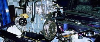
An element of the car, such as the crankcase ventilation system of the VAZ 2114, serves to remove unexhausted gases and re-supply them inside the engine for afterburning, as a result of which the toxicity of the exhaust is sharply reduced. But, during the operation of the car, this system becomes clogged, resulting in problems with the engine. Today we’ll talk about what crankcase ventilation includes and how to clean it with your own hands.
Crankcase ventilation system
Malfunction: the crankcase ventilation system is clogged
Many car owners have a vague idea about the crankcase ventilation system of their car. Since for a long time, while the car has low mileage, it works unnoticed, without giving away its existence. After years and (or) hundreds of thousands of miles, the ventilation system gradually becomes clogged, showing the first signs of its malfunction.
Signs of malfunction: the crankcase ventilation system is clogged
Drives engine oil out of the engine under seals and gaskets
Since the ventilation system is responsible for the timely and effective removal of gases from the engine crankcase into its intake tract, the slightest narrowing of its channels due to the appearance of deposits in them leads to an increase in pressure in the crankcase and in the engine itself. Increased pressure causes engine oil to leak under the crankshaft and camshaft seals, pan gasket, valve cover gasket, and oil filler plug. Replacing oil seals and gaskets in such a situation does not solve the problem of oil leakage.
Engine air filter housing oil
(for carburetor engines)
Due to the reason described above for the increased pressure in the engine crankcase, the engine oil contained in it begins to be actively released along with gases under the valve cover and further into the air filter housing. Clogging the filter element and carburetor jets.
Increased engine oil consumption
Since engine oil begins to be actively released into the engine intake tract and burns out in the combustion chambers, its consumption increases accordingly. At first, almost unnoticeable, it gradually grows as the ventilation system becomes clogged.
Oiling of spark plug electrodes
Due to engine oil entering the engine intake tract and further into the combustion chambers, the spark plug electrodes become oiled. The spark plugs begin to work intermittently, the engine idles, there are dips and jerks in movement, and blue smoke from the muffler.
Causes of the malfunction: the crankcase ventilation system of the car engine is clogged
High car mileage
Sooner or later, the engine crankcase ventilation system ceases to effectively cope with its responsibilities since it constantly has to deal with crankcase gases carrying particles of oil, soot, etc. Over time, all this clogs the system’s oil separator and settles in the form of soot deposits on the walls its hoses and tubes.
Use of low-quality oils
The process of clogging of the crankcase ventilation system can be accelerated by constant operation of the car engine with low-quality and (or) engine oil unsuitable for the given engine. In this case, the amount of soot deposits increases significantly.
Wear of the engine piston group
A worn-out piston group of a car engine (rings, pistons, cylinders) allows a large volume of gases from the combustion chambers to break into the crankcase, increasing the pressure in it and contributing to the onset of negative consequences.
What to do if there are signs of clogging of the crankcase ventilation system?
Change the engine oil to an appropriate and high-quality one.
Check the compression in the engine cylinders to determine the degree of wear of its piston group.
Notes and additions
On engines in which the design of the ventilation system allows, there is a practice of eliminating the negative consequences of clogging of the ventilation system and piston wear, which consists of leading the main hose of the system under the engine. In this case, crankcase gases are released into the atmosphere. Since they are poisonous, the environment suffers.
Why is an engine crankcase ventilation system needed? The system is designed to remove gases from the engine crankcase into its intake manifold, which prevents an increase in their pressure and, as a result, oil leakage under the oil seals and seals. In addition, afterburning of harmful crankcase gases leads to a decrease in exhaust toxicity.
Closed crankcase ventilation system. With forced removal of gases (due to vacuum in the intake manifold). Gases are sampled through an oil separator, which cleans them of engine oil particles. Gases are removed through two circuits (main and idle).
Example: design of the crankcase ventilation system of a car engine.
1. Engine crankcase.
3. Hose from the breather to the valve cover pipe.
4. Oil separator under the valve cover.
5. A thin hose from the valve cover to the fitting with the throttle body nozzle.
6. Fitting with a jet on the throttle valve block.
7. Thick hose from the valve cover to the inlet pipe.
What is a PCV valve
Theoretically, without this valve, the forced ventilation system cannot work correctly a priori. After all, it is the PCV valve that doses the supply of crankcase gases to the most important area - the space behind the throttle valve, right in front of the combustion chamber.
The PCV valve is not a check valve at all, as many people think. Yes, it is not blown in the opposite direction, but it also does not simply have two positions, open and closed. Everything is much more complicated. Inside the PCV valve there is a plunger loaded with a spring, the force of which is calculated depending on the engine volume, or more precisely, on the vacuum created in the manifold.
PCV Valve Design
The valve has four operating positions:
- The engine is switched off. The valve is completely closed, gases do not enter the manifold, and now they have nothing to do there.
- The engine is running at idle speed. In this mode, the vacuum in the manifold is the highest, the valve is completely open (100%) to ensure the supply of gases (essentially air) into the throttle space. Moreover, the amount of gases is strictly regulated and clearly controlled by the ECU, and the ECU already controls the idle speed controller depending on the amount of air supplied and a number of other factors.
- The engine operates in normal mode at medium speed and medium load. The PCV valve is approximately 50% open. The flow of crankcase gases is average, they burn efficiently in the cylinders.
- Maximum load and high speed mode. The PCV valve is open by 20-25%, the maximum amount of crankcase gases is burned, thereby the pressure in the crankcase is not dangerous for oil seals and gaskets, since it is completely controlled due to the vacuum in the manifold.
Algorithm of operation of the crankcase ventilation valve
On the Lada Vesta, the ventilation system is designed in such a way that in fact it always works the way a normal system works in the fourth mode. The flow of gases is limited only by a 1.7 mm jet built into the throttle pipe. In theory, the expectation was that the system would operate as a dual-circuit system.
This is how the ventilation scheme is implemented on 8 and 16-valve VAZ engines
The first circuit operates in the speed zone from idle to 1500 rpm. The pipe behind the throttle and the same 1.7 mm jet are involved here. The second circuit is connected to the ventilation already at high speeds, and gases begin to flow into the intake manifold up to the throttle through a hose with a diameter of 18 mm.
Article: 2108-1014050, additional articles: 2108-1014050R
Order code: 004155
- You may need
- show more
- Passenger cars / VAZ / VAZ-21151 drawing
» href=»/catalog/vaz-3/legkovye_avtomobili-30/vaz_2115-65/sistema_smazki_i_ventilyacii-71/#part52916″>Upper hoseEngine / Lubrication and ventilation system
- » href=»/catalog/vaz-3/legkovye_avtomobili-30/vaz_2114-647/sistema_smazki_i_ventilyacii-50/#part1669065″>Upper hoseEngine / Lubrication and ventilation system
- » href=»/catalog/vaz-3/legkovye_avtomobili-30/vaz_2108-18/sistema_smazki_i_ventilyaciya-69/#part27785″>Upper hoseEngine / Lubrication system and ventilation
- » href=»/catalog/vaz-3/legkovye_avtomobili-30/vaz_21099-79/ventilyacionnaya_i_smazochnaya_sistema-82/#part36138″>Upper hoseEngine / Ventilation and lubrication system
- » href=»/catalog/vaz-3/legkovye_avtomobili-30/vaz_2111-11/sistema_smazki_i_ventilyacii-103/#part44719″>Upper hoseEngine / Lubrication and ventilation system
- » href=»/catalog/vaz-3/legkovye_avtomobili-30/vaz_2110__2111__2112-415/sistema_smazki_i_ventilyacii-117/#part1302779″>Upper hoseEngine / Lubrication and ventilation system
- » href=»/catalog/vaz-3/legkovye_avtomobili-30/vaz_2113-648/sistema_smazki_i_ventilyacii-50/#part1669065″>Upper hoseEngine / Lubrication and ventilation system
- » href=»/catalog/vaz-3/legkovye_avtomobili-30/vaz_2109-9/ventilyacionnaya_i_smazochnaya_sistema-82/#part32199″>Upper hoseEngine / Ventilation and lubrication system
- » href=»/catalog/vaz-3/legkovye_avtomobili-30/vaz_2110-10/sistema_smazki_i_ventilyacii-103/#part40411″>Upper hoseEngine / Lubrication and ventilation system
- » href=»/catalog/vaz-3/legkovye_avtomobili-30/vaz_2112-12/sistema_smazki_i_ventilyacii-103/#part49027″>Upper hoseEngine / Lubrication and ventilation system
How to clean the crankcase ventilation system on a VAZ 2110-VAZ 2112?
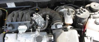
Note! Before you start work, remove the air filter housing, as it will interfere greatly; if you do not know how to do this, then read the article entitled: “Replacing the air filter housing on dozens”!
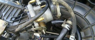
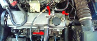
Removal: 1) The hardest thing is to remove the cylinder head cover, but the remaining parts that relate to the ventilation system (And these are mainly hoses), removing is as easy as shelling pears, in general, let's start, first you will need to disconnect the wires from each other, namely the upper connectors (see photo 1 ) and lower connectors (Indicated by a red arrow), once this is done, remove the connectors, to do this, squeeze the two latches on one connector with your fingers and remove it (see photo 2) and do the same with the other connector, just without removing it, they will interfere, and in general you won’t be able to remove the cylinder head cover without removing these connectors, because the wires simply won’t allow you to do this, both connectors were sitting on brackets, so unscrew the bolts securing them and remove both brackets from the cylinder head cover, in more detail how to do this , look at photos 3 and 4 below.
2) Now remove the exhaust manifold from the cylinder head cover, it is bolted on and by the way, when you remove it, replace all the O-rings, firstly they are not expensive and secondly, after replacement, you will be 100% sure that the collector will not let air through anywhere, since the rings will be new; you can read in more detail how to do this in the article entitled: “Replacing the receiver on a 16-valve car.”
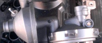
3) Then start removing the hoses, they are held in place by clamps, the clamps are loosened using a screwdriver or wrenches, if it is not convenient to work with a screwdriver, all the clamps that you will need to loosen and all the hoses that you will need to remove, you can see in the photographs a little below:
Note! Rinse the removed hoses with gasoline or kerosene, then dry them in the sun and, if possible, also blow them with compressed air (for example, a compressor), before installation, make sure that the hoses are dry, if necessary, wipe them dry with a rag and by the way, Carefully clean all those places where the hoses are connected with a cloth and remove all dirt from them!
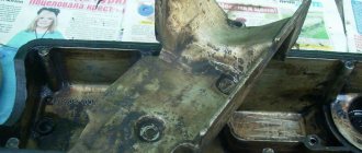
4) When everything is finished, remove the cover from the Cylinder Head, it is secured with fifteen bolts, these bolts are unscrewed with a socket wrench or a socket head and an “8” wrench, then the cover is separated from the cylinder head with a screwdriver and removed from the car, it is most convenient to separate it from the cylinder head in those places where there are special protrusions for this, one of such protrusions is indicated by a blue arrow.
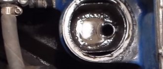
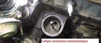
5) After you have the cylinder head cover in your hands, using a wrench or a socket wrench, unscrew the six bolts that secure the separator to it (Several bolts are indicated in the large photo) and disconnect it from the cover (see small photo).
Note! This separator is an integral part of the crankcase ventilation system, it has such a part as an oil deflector, to pull it out, you will need to compress the side clamps using pliers (see photos 1,2), a rubber o-ring will be installed on the oil deflectors, picking it up with a screwdriver , you also need to remove it (see photo 3,4) and replace it with a new one, if such a ring is difficult to find in car shops, then you are allowed not to change it if it is in good condition, namely: It should not be too compressed, the rubber is not should become rough and lose its elasticity, and there should be no cracks or other types of damage on the ring!
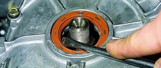
Installation: Installation of all parts is carried out in the reverse order of removal, but before installation, wash everything thoroughly with gasoline or kerosene, this also applies to the cylinder head cover itself, there should be no dirt on it, and also remove old sealant (with a screwdriver or fine-grained sandpaper) the surface where the cylinder head cover is installed, after cleaning, degrease it and apply a new sealant, as it is shown in the small photo below:
Additional video: An interesting video that will give you a little additional information on the crankcase ventilation system is located just below:
How to clean
To begin work, you will need to prepare the necessary tools, namely:
The crankcase ventilation of a VAZ 2114 is cleaned as follows:
- Loosen the fastening clamps of both pipes and then remove them.
- Inspect the pipes for cracks or chips - if the latter are present, replace the pipes with new ones of the same diameter.
- If the pipes are in good condition, clean them outside and inside with a damp cloth.
- Disconnect the throttle cable from the sector.
- Remove the pair of mounting bolts securing the throttle body to the receiver.
- Remove the bracket along with the cable.
- Unscrew the two bolts securing the cylinder head, and then remove the washers and rubber bushings located on them.
- Remove the cylinder head cover itself.
- Find the oil separator on the cylinder head cover and unscrew the mounting bolts that hold it.
- Remove the housing cover, and then remove the oil separator itself.
- Thoroughly rinse the filter mesh (oil separator) in gasoline (it is recommended to use highly purified gasoline for this) or kerosene.
- Clean the cylinder head cover from oil and adhering dirt (this is best done using a rag soaked in kerosene).
- Install the oil separator filter back into the cylinder head cover.
- Reassemble in exactly the same order, but in reverse order.
To avoid possible injuries, all work on dismantling the cylinder head cover and cleaning the ventilation system should be carried out only with the engine completely cooled.
It should be noted that when performing operations to clean the ventilation system, it is worth paying attention to the condition of the rubber bushings that fasten the cylinder head, as well as the gasket. If they are worn out or covered with cracks, they should be replaced immediately, without waiting for serious damage.
At the end of today's conversation, it is worth mentioning a situation where cleaning the crankcase ventilation system does not actually help improve engine performance. This happens when the engine is very worn out, and the secondary vapors entering it to burn out actually “choke” all its work.
There can be two ways out of this situation - either carry out a major overhaul of the power unit or remove the ventilation system to the external environment (in this case, unburned gases will not enter the engine, but into the atmosphere). True, at the same time, the environmental friendliness of the car will noticeably decrease, and it will no longer meet the high Euro standards. For this reason, such a decision should be postponed until the last resort.
Improved crankcase ventilation. beneficial improvements
Not long ago I came across an interesting article on a website. The essence of which is to change the path of crankcase gases through low crankcase ventilation.
AvtoVAZ has always allowed a small ventilation of crankcase gases into the throttle assembly, both on 8 and 16-valve engines. But, with the release of the Lada Grant and the advent of the 126th engine, the circle of low ventilation has changed, now it does not enter the throttle, but directly into the receiver. And this is more correct.
After all, by increasing the amount of air behind the throttle valve, you can reduce jerks in transient modes. Roughly speaking, make the engine more elastic.
The advantages of this modernization should be the following: • Increases traction at low speeds; • The engine jerk disappears when the throttle is closed abruptly; • Cleaner throttle assembly; • Decrease in crankcase pressure;
So, without hesitation, I decided to do this on my 8-valve engine. The materials that I read said that there would be no special effect on an 8-valve engine; it would only be noticeable on 16-valve engines.
But even on the 8-valve engine in Grant the ventilation is made directly into the receiver, which means it’s better. It’s not for nothing that AvtoVAZ came to this decision years later.
This is what the ventilation picture looks like initially
We remove the low ventilation hose; it will no longer be needed. I wanted to take clamps from it, but they don’t tighten very well
To ventilate the receiver, you will need a hose of the same diameter, only twice as long. I still have a hose for HBO in my bins (from the ramp to the injectors). It fit perfectly
I plugged the hole in the throttle assembly using a small piece of hose and a bolt. For greater reliability, I tied the ends together with plastic ties.
The receiver has two rubber plugs that are pulled together with a little effort. I had a vacuum connected to one hole from the HBO reducer, and the second was free. It was in the second hole that I connected the small crankcase ventilation circle. The hose fit freely, so I tightened it with a clamp
Now the small ventilation circle looks like this:
The new hose does not interfere with anything. When the decorative engine cover is installed, the changes are not noticeable at all.
Now about impressions. On my first test ride, I didn’t feel much of a change in traction at low revs, but there was some effect. I would say that traction improved by 5%, no more. Or maybe this is just my own self-hypnosis. But I don’t have a 16-valve one, where it should be really noticeable.
But the nods when releasing the gas almost disappeared. Everyone is familiar with the situation when you are driving in 1st or 2nd gear at a speed of over 3 thousand and sharply release the gas pedal without squeezing the clutch, the car “nods” and a noticeable nod appears.
So, now these “nods” are barely noticeable. They remain, there is no longer the feeling that someone suddenly pressed the brake.
In general, I consider the revision extremely useful and can recommend it. Simple manipulations that will take no more than 10 minutes and will increase driving comfort.
The principle of operation of the crankcase ventilation valve of internal combustion engines
The crankcase ventilation system (CVV) is simple and its operating principles are very simple. The internal space of the engine is connected to the intake manifold by a hose, and under the influence of vacuum, the carbon dioxide accumulated in the engine is taken from the inside into the intake tract, then enters the cylinders. The crankcase ventilation valve (CVVV) has a unipolar direction; it allows gases to move only in one direction (from the crankcase to the intake manifold), without letting them back.
SVKG is essentially the same breather that is found in the gearbox and automobile axles. But if in the transmission the valve opens, releasing the accumulated carbon dioxide into the surrounding atmosphere, then in the engine, under the influence of vacuum, they are removed faster and more efficiently in the internal combustion engine itself. An example can be given - on ZMZ-24 engines, open-type ventilation was previously used, and through the outlet pipe in the cover of the pushers the KGs came out (indicated by an arrow in the figure below).
Since 1977, forced closed-type SVKG began to be used - through a hose coming from the valve cover of the internal combustion engine, gases began to be diverted under the carburetor. Due to forced SVKG:
- the emission of harmful substances into the atmosphere is reduced;
- The pressure inside the crankcase is reduced more effectively, so oil seals and gaskets are not squeezed out;
- the engine does not “suffocate”, it works with normal output.
In the classic SVKG scheme, there are two gas outlets from the engine into the intake tract:
- one of them is direct-flow;
- the other is of the forced type.
Also, as an example, we can consider the ZMZ-402 engine system; in the figure below you can see that from the valve cover, gases flow through a thick pipe directly into the carburetor, and through the lower pipe into the intake manifold itself, bypassing the device that creates the necessary proportion of air with fuel.
Design and principle of operation
As was said at the very beginning, the ventilation system removes crankcase gases from the VAZ 2114 back into the engine, preventing unburned fuel oil mixture from entering the atmosphere. It includes a pair of pipes through which gases are removed, and a filter that traps solid particles and clots.
The whole system functions as follows:
- the fuel mixture entering the engine burns and forms exhaust gases, most of which are discharged from the engine into the exhaust line;
- a small part of the gases leaks through the piston rings and enters the lower pipe of the ventilation system;
- From the lower pipe, gases enter the filter (made in the form of a multilayer mesh), after which, already purified, they return to the engine, where they burn out.
How to clean the crankcase ventilation system on a VAZ 2110-VAZ 2112?
Note! Before you start work, remove the air filter housing, as it will interfere greatly; if you do not know how to do this, then read the article entitled: “Replacing the air filter housing on dozens”!
Removal: 1) The hardest thing is to remove the cylinder head cover, but the remaining parts that relate to the ventilation system (And these are mainly hoses), removing is as easy as shelling pears, in general, let's start, first you will need to disconnect the wires from each other, namely the upper connectors (see photo 1 ) and lower connectors (Indicated by a red arrow), once this is done, remove the connectors, to do this, squeeze the two latches on one connector with your fingers and remove it (see photo 2) and do the same with the other connector, just without removing it, they will interfere, and in general you won’t be able to remove the cylinder head cover without removing these connectors, because the wires simply won’t allow you to do this, both connectors were sitting on brackets, so unscrew the bolts securing them and remove both brackets from the cylinder head cover, in more detail how to do this , look at photos 3 and 4 below.
cylinder head cover
2) Now remove the exhaust manifold from the cylinder head cover, it is bolted on and by the way, when you remove it, replace all the O-rings, firstly they are not expensive and secondly, after replacement, you will be 100% sure that the collector will not let air through anywhere, since the rings will be new; you can read in more detail how to do this in the article entitled: “Replacing the receiver on a 16-valve car.”
3) Then start removing the hoses, they are held in place by clamps, the clamps are loosened using a screwdriver or wrenches, if it is not convenient to work with a screwdriver, all the clamps that you will need to loosen and all the hoses that you will need to remove, you can see in the photographs a little below:
Note! Rinse the removed hoses with gasoline or kerosene, then dry them in the sun and, if possible, also blow them with compressed air (for example, a compressor), before installation, make sure that the hoses are dry, if necessary, wipe them dry with a rag and By the way, carefully clean all those places where the hoses are connected with a cloth and remove all dirt from them!
4) When everything is finished, remove the cover from the Cylinder Head, it is secured with fifteen bolts, these bolts are unscrewed with a socket wrench or a socket head and an “8” wrench, then the cover is separated from the cylinder head with a screwdriver and removed from the car, it is most convenient to separate it from the cylinder head in those places where there are special protrusions for this, one of such protrusions is indicated by a blue arrow.
5) After you have the cylinder head cover in your hands, using a wrench or a socket wrench, unscrew the six bolts that secure the separator to it (Several bolts are indicated in the large photo) and disconnect it from the cover (see small photo).
Note! This separator is an integral part of the crankcase ventilation system, it has such a part as an oil deflector, to pull it out, you will need to compress the side clamps using pliers (see photos 1,2), a rubber o-ring will be installed on the oil deflectors, it having picked it up with a screwdriver, you also need to remove it (see photo 3,4) and replace it with a new one, if such a ring is difficult to find in car shops, then you are allowed not to change it if it is in good condition, namely: It should not be too compressed, the rubber should not become rough and lose its elasticity, and there should be no cracks or other types of damage on the ring!
Installation: Installation of all parts is carried out in the reverse order of removal, but before installation, rinse everything thoroughly with gasoline or kerosene, this also applies to the cylinder head cover itself, there should be no dirt on it, and also remove old sealant (with a screwdriver or fine-grained sandpaper) the surface where the cylinder head cover is installed, after cleaning, degrease it and apply a new sealant, as it is shown in the small photo below:
Additional video: An interesting video that will give you a little additional information on the crankcase ventilation system is located just below:
Product delivery options
Note! Below are the shipping methods available specifically for this product. Payment options may vary depending on the shipping method. Detailed information can be found on the “Delivery and Payment” page.
Parcel by Russian Post
Available payment methods:
- Cash on delivery (payment upon receipt)
- Using cards Sberbank, VTB, Post Bank, Tinkoff
- Yandex money
- QIWI
- ROBOKASSA
Shipping throughout Russia. Delivery time is from 5 to 12 days.
Parcel by Russian Post 1st class
Available payment methods:
- Cash on delivery (payment upon receipt)
- Using cards Sberbank, VTB, Post Bank, Tinkoff
- Yandex money
- QIWI
- ROBOKASSA
Shipping throughout Russia. Delivery time is from 2 to 5 days. More expensive than regular delivery by Russian Post, approximately 50%. Parcel weight up to 2.5 kg
Express Parcel EMS
Available payment methods:
- Cash on delivery (payment upon receipt)
- Using cards Sberbank, VTB, Post Bank, Tinkoff
- Yandex money
- QIWI
- ROBOKASSA
Shipping throughout Russia. Delivery time is from 3 to 7 days. More expensive than regular delivery by Russian Post, approximately 100%.
Transport companies
Available payment methods:
- Using cards Sberbank, VTB, Post Bank, Tinkoff
- Yandex money
- QIWI
- ROBOKASSA
Delivery is possible to any locality where there is a representative office of the transport company. Delivery time is from 2 to 10 days. Sending large parcels is approximately 50% more profitable than by Russian Post.
Courier delivery in Togliatti
Available payment methods:
- Cash upon receipt
- Using cards Sberbank, VTB, Post Bank, Tinkoff
- Yandex money
- QIWI
- ROBOKASSA
Delivery time from 1 to 12 hours.
Pickup from our warehouse
Available payment methods:
- Cash upon receipt
- Credit, installments
- Using cards Sberbank, VTB, Post Bank, Tinkoff
- Yandex money
- QIWI
- ROBOKASSA
Pickup times must coincide with store opening hours.
Breather oil: what to do and how to find the cause
Let's start with the fact that during engine operation, so-called crankcase gases accumulate in the crankcase. To prevent excess pressure from being created, there is a special valve for ventilation. This solution allows the closed crankcase to communicate with the atmosphere. This valve is the breather. In simple words, a breather on an internal combustion engine is actually needed to equalize the pressure inside the engine.
It should be noted that in the crankcase gases mix with oil mist. As a result, lubricant particles enter the breather. Although there is a special oil trap inside the device, a certain part of the oil may escape out. Given this information, minor contamination of the system is acceptable, which is normal. In cases where a lot of lubricant leaks, you should look separately for why oil is leaking from the breather.
On injection engines, traces of oil getting into the throttle area are noticeable, the power unit also loses its throttle response and power, and fuel consumption increases noticeably. It turns out that to check it is necessary not only to inspect the outer surfaces under the hood, but also to remove the air filter, throttle assembly, etc.
The role of the oil separator
An oil separator, often called an oil sump, is designed to capture large and fine oil particles. Its role is extremely important for the proper operation of the mass air flow sensor (MAF). As oil mist settles on the walls of the intake tract, it quickly becomes covered with dust. Because of this, the operation of the flow meter’s sensitive element is disrupted. The engine control unit receives incorrect readings about the amount of air entering the intake tract. Therefore, forced crankcase ventilation of a modern engine may include several types of oil separators.
Labyrinth oil trap
When gases move through the labyrinth, large oil particles under the influence of inertial forces are pushed towards the walls of the oil separator. The oil flows by gravity through the separator plates into the pan. An oil trap similar in operating principle, consisting of a set of plates, is installed in the valve cover of VAZ injection engines.
Cyclic oil trap
Designed to capture fine particles of oil suspension. As crankcase gases pass around the circumference of the oil separator housing, oil droplets move outward, settling on the walls of the oil separator housing.
Oil separator with filter element
Filter paper or fiberglass filler is installed inside the housing. Passing through the filter, the oil is retained on the walls of the filter element, after which it flows into the pan.
Turbulence of exhaust gas flows moving through the crankcase ventilation hose impairs the uniform filling of the cylinders. Therefore, many cars have an additional sedation chamber installed. In addition to a gas flow retarder, the chamber also acts as an additional oil separator.
Pipe from valve cover VAZ 2114
- To the beginning of the forum
- Forum Rules
- Old design
- FAQ
- Search
- Users
Cleaning the remote control has nothing to do with it, I tell me not to blow out the tube on the valve cover itself, I blow under the valve cover, but don’t BLOW there, maybe there’s a check valve there.
hose that lubricates the throttle
Cleaning the remote control has nothing to do with it, I tell me not to blow out the tube on the valve cover itself, I blow under the valve cover, but don’t BLOW there, maybe there’s a check valve there.
hose that lubricates the throttle
and what goes out of the thicker valve cover into the corrugation?
and what goes out of the thicker valve cover into the corrugation?
thicker - this is when the car is at revs, and when the throttle is closed at XX, only the small one works. (6. Use a Phillips screwdriver to loosen the fastening clamp and remove the crankcase ventilation hose (1st circuit) from the throttle assembly fitting.)
Moreover, when the ventilation at XX is clogged, the oil begins to press into the corrugation
Wow
. I decided to tell my father GVG about the throttle :-D.
Source
Why is cleaning necessary and its frequency?
When the ventilation system is clogged, an emulsion containing soot and oil residues settles inside the engine, resulting in the creation of excess pressure, leading to damage to the seals. This leads to loss of sealing and oil leaks, which can be seen during an external inspection of the engine block. Crankcase gases are gases from engine cylinders that are not discharged through the exhaust valve, but are squeezed out into the crankcase through the gaps of the pistons and piston rings when the engine is running. This process occurs especially intensively in worn-out engines with high mileage. For VAZ 2101-2107, these are mileages of 80-100 thousand km.
If the crankcase ventilation is not cleaned in a timely manner, the operation of the fuel supply system will be affected. In carburetor engines, the air filter and the carburetor itself become dirty; in injection engines, the throttle assembly, inlet pipe and sensors become dirty. All this leads to a decrease in power, problems with operation, and in some cases a complete stop of the engine. To avoid this, additional elements are introduced into the ventilation system to clean crankcase gases from emulsions containing oil.
If the crankcase ventilation system is not cleaned in a timely manner, the hoses crack due to excess pressure. This causes excess air to be sucked into the engine. Carburetor engines are not so sensitive to this problem, but in injection systems the quality of the mixture sharply deteriorates, the stability of the engine is disrupted and its power is reduced.
The best option is to clean the crankcase ventilation on a VAZ classic immediately before changing the oil. This frequency allows you to keep the system in order, change cracked hoses on time, extend the life of the engine, and reduce fuel consumption without loss of power.
How often should cleaning be performed?
If the ventilation system is clogged and its filter is unable to clean the mixture passing through it, then not only unburned gases, but also oil particles and other pollutants will enter the engine. All this will ultimately have a negative impact on both the operation of the engine and its remaining service life.
The frequency with which the crankcase ventilation of the VAZ 2114 should be cleaned directly depends on the condition of the engine. So, if the car just recently came off the assembly line, and its engine has not clocked up 50,000 km, you shouldn’t even think about cleaning it, since the piston rings are still new, and there is practically no leakage of gases through them.
The first cleaning (as recommended by AvtoVAZ itself) should be performed after the car has covered 60,000 km. And all subsequent cleanings should also be performed after every 60,000 km.
Many owners of domestic cars with extensive experience say that 60,000 km is too much, and cleaning should be done at least every 30,000 km - this will help avoid many problems with the engine and extend its life. In this case, the first cleaning should be carried out after the first 60,000 km.
Necessary tool
To clean the breather on a VAZ engine, check and replace the hoses, you don’t need any special skills or specialized equipment; a standard kit is enough. To complete the work you will need:
- set of keys No. 7-13;
- flat and Phillips screwdrivers;
- washing liquid, kerosene will do;
- container where washing will take place;
- rags;
- breather gasket;
- heat-resistant silicone-based sealant;
- if necessary, a set of new hoses will be required - separately for the carburetor and injector.
This tool can be found in any garage, so there are no problems with its selection. It is better to take rags that do not separate into individual elements, since during washing they can get into the engine.