April 20, 2017 Lada.Online 185 275 64
If, while operating a LADA car, you notice that during load (when the air conditioner is running, the heating is on, etc.) in a traffic jam, the engine begins to operate unstably (troits, pulls poorly, etc.), perhaps the reason lies in the ventilation system crankcase The article proposes to solve the problem by installing a PCV valve from a foreign car.
Installation and cleaning of the crankcase ventilation system in Lada Priora
When creating new car models, special attention is paid to environmental protection. Thus, the crankcase ventilation system (Priora, Kalina) has been modernized, which meets modern environmental safety requirements. It ensures the removal of combustion products of the fuel-air mixture, which collect in the oil pan as a result of exiting through the not very tightly fitting piston rings to the cylinder walls.
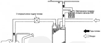
Diagram of the standard crankcase ventilation system
The crankcase ventilation system of VAZ engines consists of two circuits that operate at different load modes and speeds:
- The small ventilation circuit is connected to the valve cover and the intake manifold (behind the throttle body). This connection diagram provides intensive crankcase ventilation due to the vacuum that occurs in the intake manifold when the throttle is closed. To avoid an effect such as hyperventilation, the cross-section of the small circuit is limited by a jet in the cable throttle body with a diameter of 1.7 millimeters. This circuit operates in the region of 800-1500 rpm.
- A large ventilation circuit is connected to the valve cover and the air pipe (in the pre-throttle space). This scheme provides intensive crankcase ventilation at high speeds. The cross section of the large contour is 16-18 millimeters
Examples demonstrating the shortcomings of the standard crankcase ventilation system:
- A car is going down a hill with the gear in gear. In this mode, the engine operates at higher speeds with a reduced load. A high vacuum is created in the crankcase, and a large ventilation circuit is connected, in which there are no control valves. Since both circuits are connected to one volume of the oil trap, a strong vacuum in the crankcase will draw a fresh portion of air bypassing the throttle. The mass air flow sensor will show increased air flow, and the ECU will try to close the throttle. Having realized that this is not possible (it is already closed), the lean mixture will be corrected by increasing the fuel supply (fuel consumption will increase). As a result, the entire internal volume of the engine will work as a parallel receiver of very significant volume, connected to the intake, bypassing the throttle. It is this volume that will interfere with the formation of a high-quality mixture.
- A car in a traffic jam drives under tension with additional consumers (for example, the air conditioner is on). The compressor clutch is connected, the load increases abruptly. The engine does not have enough air, it begins to pull it from the crankcase, bypassing the throttle. But the ECU is also aware of the clutch engagement and also supplies more air by opening the throttle. The vacuum drops sharply, the vacuum brake booster (VBR) does not have enough strength to hold the car. Leap forward. The ECU sees an increase in oxygen and closes the throttle. A sharp increase in vacuum, VUT seizes. The car jerks, the transmission hits. And so on ad infinitum.
As a result, in both cases, when the engine is running, speed jumps occur and the engine choke under the load. Jerking and vibration are possible on manual transmissions, automatic transmissions and automatic transmissions. To eliminate these shortcomings, it is proposed to modify the design according to one of the presented schemes.
Operating principle of SVKG
Car engines have a ring gas exhaust system. The resulting gases as a result of the combustion of diesel fuel, gasoline or liquefied gas are not released into the environment, but are returned to the engine, where they are re-burned. The second end of the crankcase ventilation hose is attached to the intake manifold, with the help of which gases again enter the cylinder chamber for combustion. A significant part of the gases, when re-entered, ignite at the moment the fuel ignites, and the remaining ones are released into the atmosphere using the exhaust system. A small percentage of the gases are sent back into the cylinder chamber for re-combustion. This process is ongoing.
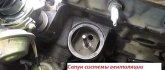
SVKG device in Lada Priora
In all brands of cars, the SVKG is built on a similar principle. Only small details differ. On the upper side of the crankcase there is an oil separator, which looks like a hollow plug. An oil deflector is placed under the plug, which is designed to clean the gases from the crankcase as much as possible from oil particles. The oil separator has an outlet for the crankcase ventilation hose.
In order for the gases to return to the cylinder chamber, a ventilation valve is placed along their path. The valve has three modes, which allows you to maintain a certain level of gas rarefaction in the crankcase.
While the engine is idling, gases move through a small circuit hose through a special passage hole in the throttle assembly. At this time, a high vacuum is created in the intake hose, which allows crankcase gases to be effectively sucked out of the throttle block. The passage hole in the throttle regulates the amount of gases that are sucked out.
This allows you to stabilize the engine in idle mode. When the car begins to move, the throttle valve opens, causing gases from the crankcase to enter the cylinder through a large circuit hose for combustion.
Priora crankcase ventilation system 16 valves
The power plant of any car is a very complex device, including mechanisms and systems that interact with each other. At the same time, the engine is not a closed hermetically sealed circuit and it also has ventilation.
Crankcase ventilation is a scheme that ensures the removal of gases from internal cavities.
The fact is that during combustion of the working mixture in the cylinders, exhaust gases are formed, which are under pressure, due to which part of them penetrates into the sub-piston space - the crankcase, where it mixes with oil mist and moisture formed as a result of condensation.
This whole mixture is called crankcase gases.
Based on this, it follows that the main task of the ventilation system is to maintain pressure inside the engine and prevent it from exceeding the permissible norm by removing crankcase gases.
Schemes for upgrading the crankcase ventilation system
Schemes for modifying the crankcase ventilation system, as well as a description, are provided by IgorRV.
For LADA cars with manual transmission and AMT (“robot”), scheme No. 1 “Crankcase ventilation scheme with PCV valve for E-GAS and cable throttle” is suitable:
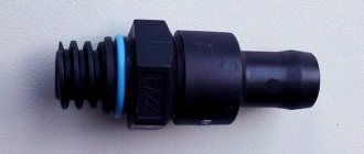
It is necessary to install a PCV valve (article 94580183, price about 400 rubles) from a foreign car into the small crankcase ventilation circuit. When connecting the PCV valve to a small circuit on an E-GAS, use a new hose (petrol-oil-resistant 8 mm without fabric reinforcement). On a cable choke, connect to the receiver, not to the choke.
As a result, the valve will shut off the circuits in transient modes, which will allow:
- Accept the load without jerking or dropping engine speed (for example, when the compressor is running, heated windows, seats, etc.).
- Reduce vibration load at idle
- Increase traction from the bottom (noted by owners of automatic transmission with VAZ-21126 engine, manual transmission with VAZ-21227, 21126 and 11186 and AMT with VAZ-21127).
- Get a sharper response to the gas pedal and faster shifts (on AMT). Perhaps due to the fact that the valve does not allow the engine to slow down, maintaining a more optimal switching algorithm.
- Reduce oil consumption through ventilation.
The valve replacement period is 40,000 km.
For LADA cars with automatic transmission (Jatco) and AMT (“robot”), scheme No. 2 is suitable:
Description of scheme No. 2: The pressure reducing valve is connected in series to a large ventilation circle. Thus, it regulates the flow of crankcase gases at high speeds and during transient processes. This allows:
- Exercise full control over the flow of crankcase gases between the small and large circuits.
- Improve engine operating mode.
- Reduce vibration load.
- Reduce oil release into ventilation.
For LADA cars with automatic transmission (Jatco) and AMT (“robot”), scheme No. 3 is suitable:
Description of scheme No. 3: To improve the operation of the braking system and facilitate the process of holding the car on the brakes in mode “D”, an “Ejection Pump” was used. Due to the flow of crankcase gases from the small circuit, the vacuum in the tube leading to the vacuum booster increases. This happens at low speeds, which is very helpful when driving in traffic jams. Keeping your foot on the brake all the time is not very easy, but this pump makes the task easier.
- Getting rid of vibrations, failures, transmission shocks.
- The engine begins to operate more calmly and softly.
- The force on the brake pedal becomes less.
- The air conditioner turns on almost imperceptibly.
- ejection pump (article 10793 VIKA, price 546 rubles);
- pressure reducing valve (article 1117701500 JP GROUP, 422 rubles);
- PCV valve (article 94580183 GENERAL MOTORS, 400 rubles);
- clamps (about 10 pieces, 600 rubles);
- thin, petrol-resistant 8 mm hose 50 cm (100 rubles);
- standard ventilation pipe.
SVKG device in Lada Priora
In all brands of cars, the SVKG is built on a similar principle. Only small details differ. On the upper side of the crankcase there is an oil separator, which looks like a hollow plug. An oil deflector is placed under the plug, which is designed to clean the gases from the crankcase as much as possible from oil particles. The oil separator has an outlet for the crankcase ventilation hose.
Cleaning SVKG in Lada Priora
After prolonged use, gas deposits accumulate in the crankcase ventilation system. This deposit makes it difficult for gases to pass into the cylinders. As a result, the gas pressure in the engine increases, which leads to oil leakage. Timely cleaning of the SVKG will help prevent this. The manufacturer of Lada Priora recommends carrying out this procedure after every 60 thousand kilometers. This service manipulation can be performed in a car workshop or independently.
To do this, you need to have tools (narrow pliers, 8mm nut wrench, Phillips screwdriver).
When cleaning the SVKG yourself, you need to perform the following steps:
- Remove the decorative engine cover.
- Remove the air filter.
- Carefully loosen the clamp on the ventilation hose clamp on the engine.
- Remove the crankcase ventilation hose (CVH) from the air supply sleeve.
- Loosen the clamp on the air supply sleeve.
- Disconnect the air vent hose from the throttle assembly.
- We loosen the clamp of the clamp and disconnect the ShVK of the large branch from the cylinder head cover (cylinder head).
- Using the same actions, we remove the small branch shvk, disconnecting it from the cylinder head cover and the throttle fittings.
- Loosen the clamp of the inlet ShVK clamp.
- We remove the supply ventilation hose and remove it from the cylinder head cover.
- Disconnect the supply ventilation hose from the cylinder head pipe.
- We wash all the hoses with gasoline, blow them out and dry them with a hairdryer. We also clean and dry all pipes and hose connections.
- Unscrew the cylinder head cover.
- We remove the separator by tightening its fastening in the form of 6 bolts, which are located inside the cylinder head cover.
- Using pliers, squeeze the oil deflector clamps and pull it out.
- Using a screwdriver, pull out the ring-shaped rubber seal. If it has lost its shape, then replace it with a new one.
- We clean the cylinder head cover and all mating surfaces from the sealant and degrease it with gasoline. Before installing the cylinder head cover, apply new sealant.
- We assemble the SVKG in reverse order.
While the engine is running, it is prohibited to break the tightness of the SVKG, as well as to remove the oil filler cap.
This will lead to the release of toxic substances into the environment and disruption of the crankcase.
Cleaning the crankcase ventilation system of the VAZ 2170 Priora
- Repair manuals
- Repair manual for VAZ 2170 (Priora) 2004+.
- Cleaning the crankcase ventilation system
Over time, tarry deposits from crankcase gases accumulate in the engine crankcase ventilation system, making it difficult to remove these gases into the engine cylinders for combustion.
Because of this, the gas pressure inside the engine increases and oil leaks through the seals appear. To avoid this, periodically clean and flush the system. According to the manufacturer's recommendation, the crankcase ventilation system must be cleaned every 60 thousand kilometers.
| Helpful Hint: Clean the crankcase ventilation system before each oil change. |
You will need: an “8” wrench, a Phillips-blade screwdriver, and pliers with narrow jaws.
1. Remove the decorative engine cover (see “Removing and installing the decorative engine cover” ).
2. Remove the air filter (see “Removing and installing the air filter” ).
| 3. Loosen the clamp... | 4. ...and disconnect the hose of the large branch of the crankcase ventilation system from the air supply hose. |
| 5. Loosen the clamp... | 6. ...and disconnect the air supply hose from the throttle assembly. |
| 7. After loosening the clamp, disconnect the hose of the large branch of the crankcase ventilation system from the cylinder head cover and remove it. | 8. Similarly, remove the hose of the small branch of the crankcase ventilation system by disconnecting it from the fittings of the throttle assembly and the cylinder head cover. |
| 9. Loosen the clamp... | 10. ...and remove the supply hose of the ventilation system by disconnecting it from the pipe of the cylinder head cover... |
11. ...and in the same way from the cylinder block fitting.
12. Rinse the hoses with gasoline or kerosene, blow with compressed air and dry. Clean the holes in the fittings and pipes for connecting the hoses.
13. Remove the cylinder head cover (see Replacing the cylinder head cover gasket).
| 14. Remove the six bolts securing the separator from the inside of the cylinder head cover... | 15. ...and remove the separator. |
| 16. Squeeze the separator oil deflector clamps with pliers... | 17. ...and remove the oil deflector from the oil separator. |
| 18. Carefully pry off the rubber O-ring with a screwdriver... | 19. ...and take it off. Replace a ring that is severely compressed or has lost its elasticity with a new one. |
| Note Before installing the cylinder head cover, clean (remove old sealant) and degrease the mating surfaces of the cylinder head and cylinder head cover. Apply a thin layer of sealant to the mating surface of the cylinder head. |
20. Install hoses and parts in the reverse order of removal.
↓ Comments ↓
1. Car structure
1.0 Car structure 1.1 General information about the car 1.2 Passport data 1.3 Car keys 1.4. Controls 1.5. Heating and ventilation of the cabin 1.6 Ensuring a comfortable air temperature in the cabin 1.7. Doors 1.8. Passive safety equipment on the car 1.9. Seats
2. Recommendations for use
2.0 Recommendations for use 2.1. Safety rules and recommendations 2.2 Running in the car 2.3 Operating the car during the warranty period 2.4. Preparing the car for departure
3. Problems along the way
3.0 Malfunctions along the way 3.1. The engine does not start 3.2 Malfunctions of the fuel injection system 3.3 Idle speed has disappeared 3.4. Interruptions in the operation of the 3.5 engine. The car moves jerkily 3.6 The car accelerates poorly 3.7 The engine stalled while driving 3.8. Oil pressure dropped to 3.9. Engine overheating 3.10. The battery does not recharge 3.13. Knocks in the engine 3.16. Wheel puncture
4. Maintenance
4.0 Maintenance 4.1. General provisions 4.2. Inspection work 4.3. Lubrication and filling works 4.4. Diagnostic work 4.5. Repair and adjustment work
5. Engine
5.0 Engine 5.1 Design features 5.2 Possible engine malfunctions, their causes and solutions 5.3 Useful tips 5.4 Checking compression in the cylinders 5.5 Removing and installing the decorative engine casing 5.6 Removing and installing the engine splash guard 5.7 Installing the piston of the first cylinder to the TDC position of the compression stroke 5.8 Replacing the drive belt gas distribution mechanism and tension roller 5.9 Replacing the power unit supports 5.11. Replacing engine seals 5.13. Engine cylinder head 5.15. Engine repair 5.16. Lubrication system 5.17. Cooling system 5.18. Power supply system 5.19. Design Features
6. Transmission
6.0 Transmission 6.1. Clutch 6.2. Gearbox 6.3. Front wheel drives
7. Chassis
7.0 Chassis 7.1. Front suspension 7.2. Rear suspension
8. Steering
8.0 Steering 8.1 Design features 8.2 Possible steering malfunctions, their causes and solutions 8.3. Steering column 8.4. Steering linkage 8.5. Steering gear
9. Brake system
9.0 Brake system 9.1 Design features 9.2 Possible malfunctions of the brake system, their causes and solutions 9.3 Bleeding the brake system hydraulic drive 9.4 Removing and installing the vacuum brake booster 9.5 Replacing the brake pedal axle bushings 9.6. Main brake cylinder 9.7. Front wheel brakes 9.8. Braking mechanisms of the rear wheels 9.9. Pressure regulator 9.10. Brake hoses and tubes 9.11. Parking brake
10. Electrical equipment
10.0 Electrical equipment 10.1 Design features 10.2. Battery 10.3. Mounting block (relays and fuses) 10.4. Generator 10.5. Starter 10.6. Ignition switch (lock) 10.7. Electronic engine control system (ECM) 10.8. Ignition system 10.9. Lighting, light and sound signaling 10.10. Windshield cleaner 10.11. Washer reservoir 10.12. Electric fan of the engine cooling system 10.13. Electric motor of the heating and ventilation system fan 10.15. Cigarette lighter 10.16. Instrument cluster 10.18. Electronic anti-theft remote control system 10.19. Immobilizer 10.21. Replacing sensors and switches
11. Body
11.0 Body 11.1 Design features 11.2 Possible body malfunctions, their causes and solutions 11.3 Removing and installing windshield frame lining 11.4 Removing and installing soundproofing upholstery in the engine compartment 11.5. Removing and installing bumpers 11.6 Removing and installing the fender liner and protective wing cover 11.7 Removing and installing the front fender 11.8 Removing and installing decorative sill trims 11.9. Hood 11.10. Trunk lid 11.11. Doors 11.12. Seats 11.13. Seat belts 11.14. Rear view mirrors 11.15. Interior fittings 11.16. Instrument panel 11.17. Heater 11.20. Body care
12. Applications
12.0 Appendix 12.1 Appendix 1. Tightening torques of threaded connections, Nm 12.2 Appendix 2. Fuels, lubricants and operating fluids 12.3 Appendix 3. Nominal filling volumes 12.4 Appendix 4. Basic data for adjustments and monitoring 12.5 Appendix 5. Spark plugs used on vehicles 12.6 Appendix 6. Lamps used on a car 12.7 Appendix 7. What you need to have in a car 12.8 Appendix 8. Tools used when repairing a car
13. Electrical diagrams
13.0 Electrical Diagrams 13.1 Diagram 1. Instrument Panel Harness Connections 13.2 Diagram 2. Vehicle Front Wire Harness Connections 13.3 Diagram 3. Engine Electronic Control System (ECM) Harness Connections 13.4 Diagram 4. Vehicle Rear Wire Harness Connections 13.5 Diagram 5. Light Harness Connections license plate light 13.6 Diagram 6. Left front door wiring harness connections 13.7 Diagram 7. Right front door wiring harness connections 13.8 Diagram 8. Rear door wiring harness connections
Cons of SVKG in Lada Priora
By cleaning the atmosphere from the emission of toxic substances, SVKG creates problems for the engine. The gases that are removed from the pan, despite the presence of an oil separator, are saturated with microscopic oil particles, which after some time leads to contamination of the fuel intake system.
This leads to engine interruptions. Gas particles settle on the valve components, which leads to its failure. This disrupts the fuel injection system into the combustion chamber and increases oil consumption. If contamination is severe, fuel injection does not occur. In this case, the valve must be completely replaced. It is necessary to periodically inspect the crankcase ventilation hoses, because under the influence of the environment they age and crack.
If you detect oil stains, an increase in the amount of oil consumption, an increase in the consumption of fuel and lubricants, as well as disturbances in the engine (stopping, does not start for a long time, makes exhaust and other uncharacteristic sounds), be sure to immediately contact a service center to have the engine checked and repaired. Timely treatment will reduce the cost of engine repairs and prolong its operation.
Source
Replacing crankcase gas pipes in Lada Priora
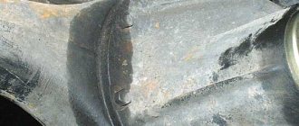
I have long noticed oil stains on the cylinder block near the breather outlet (crankcase gas pipe), it was time to replace the pipe, but since it doesn’t affect the speed, I didn’t want to go there. There was also some slight fogging at the inlet of the breather pipe into the valve cover and the upper pipe entering the throttle sleeve, and near the oil pressure sensor. The other day on Drive, the topic of engine fogging came up, and I decided not to put it off any longer and still start replacing the pipes. Since the car does not have an air conditioner, there is access to the lower clamp of the breather pipe, although it is not entirely convenient. I knew that I would rip everyone off again, but I put up with it, just so as not to crawl under the car and remove the protection, because... I have neither a pit nor a lift. Replacement is not difficult, see photos for details.
This beauty of oil and dust has grown on my cylinder block!
The breather pipe inlet into the valve cover is almost dry.
The outlet from the valve cover is also covered in oil, but the inlet to the throttle sleeve is dry.
The thin hose is also snotty.
Oil at the inlet of a thin hose into the receiver.
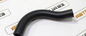
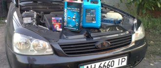
I bought two new pipes and a bottle for washing the engine.
The pipes were, as they say, dry. I decided to put them on sealant.
Heroes of the occasion!
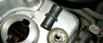
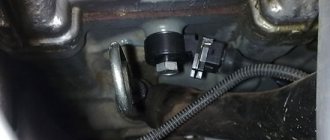
I also decided to inspect the knock sensor, because... Periodically, error 0327 (low signal level of the knock sensor) appears on the on-board vehicle. I haven’t noticed any changes in engine performance yet, but I feel that the sensor will soon be replaced.
I took off the block, the terminals are dry, the wires are intact.
Before applying the sealant, all fittings were thoroughly cleaned and degreased with gasoline.
The new pipe is in place. Engine washing liquid doesn’t do a very good job with such a layer of dirt; I wiped it with a rag as best I could.
Rinse the top. There is not a lot of dirt, the engine was washed quite recently.
Another additional seal. Self-adhesive D-shaped profile (the thickest), placed on the top bar of the grille. There is a benefit from it, since the installed seal from the classics still allows splashes and dirt to pass through the center.
I washed all the snotty places, sealed the pipes and hoses with sealant. Let's see how long the engine stays dry.
https://www.drive2.ru/l/3685250/
next article:
Replacing the thermostat and connecting engine operation monitoring with a tachometer alarm in Lada Priora
The first winter, and with the new car, I revealed some “childhood” diseases that occur in most prior drivers:
Rating 0.00 [0 Vote(s)]
Operating principle of SVKG
Car engines have a ring gas exhaust system. The resulting gases as a result of the combustion of diesel fuel, gasoline or liquefied gas are not released into the environment, but are returned to the engine, where they are re-burned. The second end of the crankcase ventilation hose is attached to the intake manifold, with the help of which gases again enter the cylinder chamber for combustion. A significant part of the gases, when re-entered, ignite at the moment the fuel ignites, and the remaining ones are released into the atmosphere using the exhaust system. A small percentage of the gases are sent back into the cylinder chamber for re-combustion. This process is ongoing.
Lada 2110 PhiX › Logbook › Refinement of the small VAZ crankcase ventilation circuit
Hi all! Recently, looking at a photo of the 127 engine, I noticed one interesting point. There is no fitting on the throttle valve for the low ventilation hose, and the hose itself is connected directly to the receiver.
The MV hose is marked in brown.
I decided to study the issue in more detail, and as it turned out, the ventilation was done in a similar way on the 8-valve grant engine.
Literally following the first link I came across a forum where this topic has been discussed for a long time, even before the appearance of new motors with a similar circuit. www.autolada.ru/viewtopic.php?t=239559&start=575
The transfer of a small ventilation circuit from the throttle to the receiver is a kind of modification aimed at reducing jerks in transient conditions. The essence of the modification is as follows: disconnect the thin crankcase ventilation hose from the throttle body and stick it into the free fitting on the intake receiver (the one that is closed with a plug). Close the loose fitting on the remote control with a plug. Thus, you increase the air flow, bypassing the throttle valve and its sharp slamming will not result in a jerk in the engine. At the same time, crankcase ventilation increases - unburned products breaking into the crankcase through the piston rings are perfectly prepared for combustion and create additional thrust at the bottom (especially noticeable at 16v).
Refinement of small crankcase ventilation - logbook Lada 2112 Dvinuyn 2005 on DRIVE2
I decided to improve the low crankcase ventilation. I’ll start by telling you why a crankcase gas recirculation system (CGR) is needed. During operation of the internal combustion engine, crankcase gases accumulate in the oil pan, which enter through piston rings that do not fit tightly to the cylinder walls. To relieve pressure in the crankcase, they came up with a crankcase gas recirculation system. If previously crankcase gases were vented into the atmosphere on cars, now it is prohibited, since we do not comply with EURO-4, 5, 6 standards... Our cars are equipped with a closed SRKG. Thus, the circulation of crankcase gases occurs. Of course, this system has its drawbacks - crankcase gases capture oil particles, forming a slight mist, and re-enter the engine, passing through the remote control, IAC, receiver, valves, and thus the intake becomes contaminated, and this in turn negatively affects operation engine (squeezes out the internal combustion engine plugs). The greater the mileage of the car, the greater the amount of deposits. You can often find cars with snotty pipes, sensors and a sweaty motor. Therefore, it is necessary to monitor crankcase ventilation.
SVKG device in Lada Priora
In all brands of cars, the SVKG is built on a similar principle. Only small details differ. On the upper side of the crankcase there is an oil separator, which looks like a hollow plug. An oil deflector is placed under the plug, which is designed to clean the gases from the crankcase as much as possible from oil particles. The oil separator has an outlet for the crankcase ventilation hose.
In order for the gases to return to the cylinder chamber, a ventilation valve is placed along their path. The valve has three modes, which allows you to maintain a certain level of gas rarefaction in the crankcase.
While the engine is idling, gases move through a small circuit hose through a special passage hole in the throttle assembly. At this time, a high vacuum is created in the intake hose, which allows crankcase gases to be effectively sucked out of the throttle block. The passage hole in the throttle regulates the amount of gases that are sucked out.
This allows you to stabilize the engine in idle mode. When the car begins to move, the throttle valve opens, causing gases from the crankcase to enter the cylinder through a large circuit hose for combustion.
Options for creating forced crankcase gas cleaning
The truth is that not everything is as simple as it seems at first glance. There are two approaches by which forced crankcase ventilation can be performed. Exhaust gases can be removed from the crankcase, and perhaps the opposite effect is the flow of air from outside.
An example of how a forced crankcase ventilation system based on exhaust gas removal is constructed is given above. In this case, the exhaust gases that have broken through are under the influence of vacuum in the intake manifold and enter through the oil separator (1), valve (2) and through hoses, having been cleared of oil particles, they again enter the engine cylinders.
An option when the ventilation system is built on the influx of fresh air is shown in the figure below. In this case, outside air enters the engine crankcase, mixes with crankcase gases, and flows back into the engine cylinders through a special PCV valve. A ventilation system constructed in this way avoids the release of internal combustion engine products into the atmosphere. This is exactly the approach used by modern automakers when designing and manufacturing cars.
To maintain normal engine operation at idle, the PCV valve blocks the exit of gases from the crankcase when there is a deep vacuum in the pipeline.
An indispensable attribute of a modern internal combustion engine is crankcase ventilation, most often designed as a closed system. It allows you to increase the reliability of the engine and reduce the negative impact of vehicle exhaust on the atmosphere. » alt=»»>
Diagnosing the cause of oil rush
Since there are a large number of reasons for oil leaking through the breather, a comprehensive check of the engine is necessary to determine exactly why the problem arose.
At the same time, to carry it out, you don’t even need to disassemble the power plant, it’s just enough to take measurements of some parameters, as well as visually assess the condition of the ventilation.
For example, let's take the already mentioned VAZ-2110. Let's assume that in the engine of this car, plaque and oil deposits were noticed in the intake manifold, which indicates oil leakage through the breather.
To determine what caused this problem, you will need little - a set of open-end wrenches, a screwdriver, a compression gauge.
We'll start the test by assessing the exhaust gases. To do this, just start the engine and look at their color shade.
If it is gray or black in color, this indicates oil getting into the cylinders due to wear or sticking of the CPG rings or problems with the timing belt. Only this can help determine the cause; read more here - the causes of smoke from the exhaust pipe.
It is also necessary to check the compression in all cylinders. In the normal state of the cylinder-piston group, it should be in the range of 11-13 MPa. The difference between the readings in the cylinders is allowed to be no more than 1 MPa.
If the compression in one cylinder is significantly lower, it can cause oil leakage.
But why exactly this is happening - rings or valves - can be determined by the spark plug that was installed on this cylinder.
Heavy carbon deposits on it will indicate a problem with the CPG.
But if the compression is low, and the spark plug has a normal working appearance without carbon deposits, you should check the valves.
Cleaning SVKG in Lada Priora
After prolonged use, gas deposits accumulate in the crankcase ventilation system. This deposit makes it difficult for gases to pass into the cylinders. As a result, the gas pressure in the engine increases, which leads to oil leakage. Timely cleaning of the SVKG will help prevent this. The manufacturer of Lada Priora recommends carrying out this procedure after every 60 thousand kilometers. This service manipulation can be performed in a car workshop or independently.
To do this, you need to have tools (narrow pliers, 8mm nut wrench, Phillips screwdriver).
When cleaning the SVKG yourself, you need to perform the following steps:
- Remove the decorative engine cover.
- Remove the air filter.
- Carefully loosen the clamp on the ventilation hose clamp on the engine.
- Remove the crankcase ventilation hose (CVH) from the air supply sleeve.
- Loosen the clamp on the air supply sleeve.
- Disconnect the air vent hose from the throttle assembly.
- We loosen the clamp of the clamp and disconnect the ShVK of the large branch from the cylinder head cover (cylinder head).
- Using the same actions, we remove the small branch shvk, disconnecting it from the cylinder head cover and the throttle fittings.
- Loosen the clamp of the inlet ShVK clamp.
- We remove the supply ventilation hose and remove it from the cylinder head cover.
- Disconnect the supply ventilation hose from the cylinder head pipe.
- We wash all the hoses with gasoline, blow them out and dry them with a hairdryer. We also clean and dry all pipes and hose connections.
- Unscrew the cylinder head cover.
- We remove the separator by tightening its fastening in the form of 6 bolts, which are located inside the cylinder head cover.
- Using pliers, squeeze the oil deflector clamps and pull it out.
- Using a screwdriver, pull out the ring-shaped rubber seal. If it has lost its shape, then replace it with a new one.
- We clean the cylinder head cover and all mating surfaces from the sealant and degrease it with gasoline. Before installing the cylinder head cover, apply new sealant.
- We assemble the SVKG in reverse order.
While the engine is running, it is prohibited to break the tightness of the SVKG, as well as to remove the oil filler cap.
This will lead to the release of toxic substances into the environment and disruption of the crankcase.
How to clean the crankcase ventilation system on a VAZ 2110-VAZ 2112?
Note! Before you start work, remove the air filter housing, as it will interfere greatly; if you do not know how to do this, then read the article entitled: “Replacing the air filter housing on dozens”!
Removal: 1) The hardest thing is to remove the cylinder head cover, but the remaining parts that relate to the ventilation system (And these are mainly hoses), removing is as easy as shelling pears, in general, let's start, first you will need to disconnect the wires from each other, namely the upper connectors (see photo 1 ) and lower connectors (Indicated by a red arrow), once this is done, remove the connectors, to do this, squeeze the two latches on one connector with your fingers and remove it (see photo 2) and do the same with the other connector, just without removing it, they will interfere, and in general you won’t be able to remove the cylinder head cover without removing these connectors, because the wires simply won’t allow you to do this, both connectors were sitting on brackets, so unscrew the bolts securing them and remove both brackets from the cylinder head cover, in more detail how to do this , look at photos 3 and 4 below.
Inspection and cleaning of the ventilation system
On the VAZ-2110 this is done like this:
- Disconnect the pipes from the breather, valve cover, air pipe and check the degree of clogging. If necessary, they can be washed in gasoline or kerosene and then dried;
Unscrew the nuts securing the valve cover and remove it. On the inside there are two bolts securing the oil separator roof, which must be unscrewed;
Remove the unscrewed cap and remove the oil separator.
It is a package of special plates that can be disassembled, washed each plate separately, assembled back and put back in place.
Since the design of the system may be different on other cars, it is performed somewhat differently. But this does not change the essence of the work - all elements are removed and washed.
As for the exhaust gas control valve, which can be installed in the ventilation system, assessing the degree of contamination and cleaning it is not difficult.
It is removed, the stroke of its rod is checked, and if it jams, then the valve is simply washed in gasoline, dried and put back in place.
This is all maintenance work on the crankcase ventilation system. They are not difficult to perform, and every car enthusiast can do it.
Finally, we note that it is recommended to clean the ventilation every time the oil is changed.
Cleaning the crankcase ventilation system on VAZ 2110, VAZ 2111, VAZ 2112
Welcome! The crankcase ventilation system is needed so that the atmosphere is not clogged and the exhaust gases are allowed to burn out again, this system was implemented in many cars, starting from the VAZ 2101 and ending with cars such as Lada Priora, Lada Granta, etc., but when the engine is worn out, this system is removed by the people themselves by removing all the hoses of the crankcase ventilation system, usually into a bottle, or just outside, we will analyze this in this article, so if your car has already covered quite a lot of mileage, then this article will be useful to you benefit.
Note! We will only disassemble cleaning the ventilation on 16 valve engines; if you have an 8 valve engine, then go to the article: “Cleaning the crankcase ventilation on a VAZ 2114”, in this article this engine is described; to clean the crankcase ventilation of a 16 valve engine, you will need stock up on: Small pliers, screwdrivers with different heads and all kinds of wrenches; in addition, you will need sealant for the cylinder head cover and a new gasket!
Summary:
What does the crankcase ventilation system consist of? From the hoses, from the oil separator, from the oil deflector, all these parts can be seen in the diagram below, all of this gets dirty over time and therefore the crankcase ventilation system needs to be disassembled from time to time and cleaned inside from dirt and oil, then the engine will work normally and everything the dirt that is in the ventilation system will not fly into the engine to burn out again, but for engines that have traveled quite a long mileage (200 thousand km and more), we recommend simply putting this system in a bottle so that it does not choke the engine of the car and he was driving more or less, and to bring the crankcase ventilation into the bottle, you will need a screwdriver and a suitable (Small) container, for more details on how to do this, see the video clip which is located at the end of the article, it shows everything in detail.
When should you clean the crankcase ventilation system? It all depends on how well the engine works; if its piston rings are worn out and it constantly throws oil into the crankcase ventilation, then it will need to be cleaned much more often, unlike if the engine is new or overhauled, it’s easy to clean it in such engines a ventilation system is needed once every 40,000 thousand km. approximately (You need to clean it before changing the oil), you can do it more often if you have free time, it won’t make it worse, but a heavily polluted crankcase ventilation will make it difficult to remove crankcase gases into the cylinders, which will cause the gas pressure inside the engine to increase and the gases to there will simply be nowhere to go except for other types of seals to come out through the oil seals, and therefore oil will begin to flow through the oil seals (Mainly due to a dirty crankcase ventilation system, oil begins to flow through the front crankshaft oil seal).
Cons of SVKG in Lada Priora
By cleaning the atmosphere from the emission of toxic substances, SVKG creates problems for the engine. The gases that are removed from the pan, despite the presence of an oil separator, are saturated with microscopic oil particles, which after some time leads to contamination of the fuel intake system.
This leads to engine interruptions. Gas particles settle on the valve components, which leads to its failure. This disrupts the fuel injection system into the combustion chamber and increases oil consumption. If contamination is severe, fuel injection does not occur. In this case, the valve must be completely replaced. It is necessary to periodically inspect the crankcase ventilation hoses, because under the influence of the environment they age and crack.
If you detect oil stains, an increase in the amount of oil consumption, an increase in the consumption of fuel and lubricants, as well as disturbances in the engine (stopping, does not start for a long time, makes exhaust and other uncharacteristic sounds), be sure to immediately contact a service center to have the engine checked and repaired. Timely treatment will reduce the cost of engine repairs and prolong its operation.
Improved crankcase ventilation of Priora
When creating new car models, special attention is paid to environmental protection. Thus, the crankcase ventilation system (Priora, Kalina) has been modernized, which meets modern environmental safety requirements. It ensures the removal of combustion products of the fuel-air mixture, which collect in the oil pan as a result of exiting through the not very tightly fitting piston rings to the cylinder walls.
Operating principle of SVKG
Car engines have a ring gas exhaust system. The resulting gases as a result of the combustion of diesel fuel, gasoline or liquefied gas are not released into the environment, but are returned to the engine, where they are re-burned. The second end of the crankcase ventilation hose is attached to the intake manifold, with the help of which gases again enter the cylinder chamber for combustion. A significant part of the gases, when re-entered, ignite at the moment the fuel ignites, and the remaining ones are released into the atmosphere using the exhaust system. A small percentage of the gases are sent back into the cylinder chamber for re-combustion. This process is ongoing.
SVKG device in Lada Priora
In all brands of cars, the SVKG is built on a similar principle. Only small details differ. On the upper side of the crankcase there is an oil separator, which looks like a hollow plug. An oil deflector is placed under the plug, which is designed to clean the gases from the crankcase as much as possible from oil particles. The oil separator has an outlet for the crankcase ventilation hose.
In order for the gases to return to the cylinder chamber, a ventilation valve is placed along their path. The valve has three modes, which allows you to maintain a certain level of gas rarefaction in the crankcase.
While the engine is idling, gases move through a small circuit hose through a special passage hole in the throttle assembly. At this time, a high vacuum is created in the intake hose, which allows crankcase gases to be effectively sucked out of the throttle block. The passage hole in the throttle regulates the amount of gases that are sucked out.
This allows you to stabilize the engine in idle mode. When the car begins to move, the throttle valve opens, causing gases from the crankcase to enter the cylinder through a large circuit hose for combustion.
Cleaning SVKG in Lada Priora
After prolonged use, gas deposits accumulate in the crankcase ventilation system. This deposit makes it difficult for gases to pass into the cylinders. As a result, the gas pressure in the engine increases, which leads to oil leakage. Timely cleaning of the SVKG will help prevent this. The manufacturer of Lada Priora recommends carrying out this procedure after every 60 thousand kilometers. This service manipulation can be performed in a car workshop or independently.
To do this, you need to have tools (narrow pliers, 8mm nut wrench, Phillips screwdriver).
When cleaning the SVKG yourself, you need to perform the following steps:
- Remove the decorative engine cover.
- Remove the air filter.
- Carefully loosen the clamp on the ventilation hose clamp on the engine.
While the engine is running, it is prohibited to break the tightness of the SVKG, as well as to remove the oil filler cap.
This will lead to the release of toxic substances into the environment and disruption of the crankcase.
Cons of SVKG in Lada Priora
By cleaning the atmosphere from the emission of toxic substances, SVKG creates problems for the engine. The gases that are removed from the pan, despite the presence of an oil separator, are saturated with microscopic oil particles, which after some time leads to contamination of the fuel intake system.
This leads to engine interruptions. Gas particles settle on the valve components, which leads to its failure. This disrupts the fuel injection system into the combustion chamber and increases oil consumption. If contamination is severe, fuel injection does not occur. In this case, the valve must be completely replaced. It is necessary to periodically inspect the crankcase ventilation hoses, because under the influence of the environment they age and crack.
If you detect oil stains, an increase in the amount of oil consumption, an increase in the consumption of fuel and lubricants, as well as disturbances in the engine (stopping, does not start for a long time, makes exhaust and other uncharacteristic sounds), be sure to immediately contact a service center to have the engine checked and repaired. Timely treatment will reduce the cost of engine repairs and prolong its operation.
Tools:
- Medium Phillips screwdriver
- Medium flat screwdriver
- Compressor
- Air blowing gun
- Open-end wrench 10 mm
- Ratchet wrench
- Extension
- 8 mm head
- Head E-8
- 13 mm head
- Narrow nose pliers
- Knife
Parts and consumables:
- Technical capacity
- Gasoline/kerosene
- Separator oil deflector seal
- Sealant-gasket type LOCTITE 5910
- Solvent type 646
- Rags
Note:
Over time, on a Lada Granta car, tarry deposits from crankcase gases accumulate in the crankcase ventilation system, making it difficult to remove these gases into the engine cylinders for combustion. Because of this, the gas pressure inside the engine increases and oil begins to leak through the seals. To avoid this, periodically clean and flush the engine crankcase ventilation system.
Clean the crankcase ventilation system on your Lada Granta before each oil change.
2. Loosen the clamps and disconnect the hose of the large branch of the crankcase ventilation system from the air supply hose and the cylinder head cover.
3. Similarly, remove the hose of the small branch of the crankcase ventilation system by disconnecting it from the fittings of the throttle assembly and the cylinder head cover.
4. Loosen the clamp and disconnect the supply hose of the small branch of the crankcase ventilation system from the cylinder head cover pipe.
5. Similarly, disconnect the second end of the supply hose from the cylinder block fitting and remove the hose.
6. Rinse the hoses with gasoline or kerosene, blow with compressed air and dry. Clean the holes in the fittings and pipes for connecting the hoses.
7. Remove the cylinder head cover as described here.
8. Using an 8 mm socket, unscrew the six bolts securing the separator from the inside of the cylinder head cover (indicated in red) and remove the separator, and also squeeze the oil deflector clamps with narrow-nose pliers (indicated by a blue arrow) and remove the oil deflector from the separator.
9. Carefully pry up the cuff with a screwdriver and remove it. Replace a cuff that is severely compressed or has lost elasticity with a new one.
10. Install the hoses and parts on the vehicle in the reverse order of removal.
Note:
Before installing the cover in place, carry out all the sealing work as indicated here.
The article is missing:
- Photo of the instrument
- Photos of parts and consumables
good day friends) somehow wandering around the expanses of the drive, I came across a similar modification - www.drive2.ru/l/7059669/ in short, make a small crankcase gas circuit like on the 127 engine. The essence of the modification is “that you increase the air flow, bypassing the throttle valve and its sharp slamming will not result in a jerk in the engine. At the same time, crankcase ventilation increases - unburned products breaking into the crankcase through the piston rings are perfectly prepared for combustion and create additional traction at the bottom (especially noticeable at 16Ve).”
Drives oil through the breather: diesel and gasoline internal combustion engines
Engine diagnostics for oil leaks through the breather requires an integrated approach. There is no need to disassemble the power unit to check. It becomes clear that at the initial stage you should assess the condition of the breather, make sure it is working and clean the device if necessary. The oil level is also checked using the dipstick. If everything is fine with the level and there are no other additional signs of a problem, then it is optimal to replace the breather with a known good one.
After making sure that the breather is working properly and ventilation is at an acceptable level, you will need to make a series of measurements and assess the condition of the CPG. As already mentioned, the cause may be failed rings, that is, you will need to measure the compression in the engine.
Also, the color of the exhaust gases can additionally indicate the need to measure compression. To check, just start the engine and then evaluate the exhaust. If the engine smokes blue or gray smoke, then this may be a sign of engine oil getting into the cylinders due to worn piston rings. When checking compression, you need to take readings in each individual cylinder. In the normal state of the CPG, compression should be at 11 MPa and above (it is recommended to consult the technical literature in relation to a specific type of internal combustion engine). If a run-up is detected according to the readings in the cylinders, the differences should not exceed 1 MPa.
Failure to reduce compression will indicate that further checks will be related to the ventilation system. The method for testing this system will be considered using the example of the domestic VAZ 2110 model. Other cars may have some individual features, but the general principle will be similar.
- At the very beginning, you need to disconnect the tubes from the valve covers, breather and air duct pipe. Then the degree of contamination should be assessed. If the tubes are clogged or dirty, then they can be cleaned with carburetor cleaner or gasoline. Afterwards you will need to blow them with compressed air or dry them naturally.
- Next you need to get to the oil separator by unscrewing the fixing bolts and removing its cover. After this, the oil separator itself is removed. This device is made of special plates. It is necessary to disassemble the element and wash it. Washing can be done in gasoline and then dried.
- At the same time, it is recommended to inspect and flush the valve, and also check the stroke of the rod. This is possible after removing the device. Valve jamming can also be eliminated by washing. The entire list of actions described allows you to keep the crankcase ventilation system clean and maintain its functionality.
Let's sum it up
Taking into account the above, it becomes clear that an increase in crankcase gas pressure and oil leakage through the breather indicate a number of problems with the breather or internal combustion engine. Quick detection and elimination of faults will reduce the cost of repairing the power unit. This is true if the problem is eliminated at an early stage, that is, without the consequences that arise after a long period of ignoring the malfunction and further active operation of the engine.
Finally, we note that quite often heavy oil leaks through the breather do not appear immediately. In other words, the lubricant may leak slightly, which is sometimes unnoticeable. In other cases, about 0.5 or a liter of lubricant can escape through the breather from the lubrication system, taking into account a short mileage (on average, 1-3 thousand km). With such a significant leak, the operation of the internal combustion engine is stopped, diagnostics and repairs are carried out.
What malfunctions are indicated by the emulsion on the oil dipstick and oil filler cap? Ways to independently determine the causes of this problem.
Purpose and principle of operation of the breather. Why are breathers installed on internal combustion engines, gearboxes and axles? When it is necessary to clean the breather, useful tips and recommendations.
How to determine a burnt engine valve yourself. The main symptoms of a burnt valve, exact clarification of the causes of engine tripping. Diagnostics, useful tips.
Why oil leaks from under the gasket or valve cover housing: causes of lubricant leaks. How to fix an oil leak from under the valve cover yourself.
The main reasons for engine oil getting into spark plug wells. What should a driver do if oil flows into the spark plug well, how to carry out repairs with his own hands.
Why does engine oil start to drip or leak at the junction of the engine and gearbox. How to accurately determine the cause of a lubricant leak, methods of diagnosis and repair.
Symptoms of a Stuck PCV
- Engine misfires at idle
- Lean air-fuel mixture
- Presence of engine oil in PCV valve or hose
- Increased oil consumption
- Hard engine start
- Rough, unstable engine operation at idle
Additionally, a stuck PCV valve can cause a check engine light due to increased air flow. And the diagnostic computer may mistakenly show this error due to the mass air flow sensor or oxygen sensor, making it difficult for you to identify the real source of the problem.
Schemes for upgrading the crankcase ventilation system
Schemes for modifying the crankcase ventilation system, as well as a description, are provided by IgorRV.
For LADA cars with manual transmission and AMT (“robot”), scheme No. 1 “Crankcase ventilation scheme with PCV valve for E-GAS and cable throttle” is suitable:
It is necessary to install a PCV valve (article 94580183, price about 400 rubles) from a foreign car into the small crankcase ventilation circuit. When connecting the PCV valve to a small circuit on an E-GAS, use a new hose (petrol-oil-resistant 8 mm without fabric reinforcement). On a cable choke, connect to the receiver, not to the choke.
As a result, the valve will shut off the circuits in transient modes, which will allow:
- Accept the load without jerking or dropping engine speed (for example, when the compressor is running, heated windows, seats, etc.).
- Reduce vibration load at idle
- Increase traction from the bottom (noted by owners of automatic transmission with VAZ-21126 engine, manual transmission with VAZ-21227, 21126 and 11186 and AMT with VAZ-21127).
- Get a sharper response to the gas pedal and faster shifts (on AMT). Perhaps due to the fact that the valve does not allow the engine to slow down, maintaining a more optimal switching algorithm.
- Reduce oil consumption through ventilation.
The valve replacement period is 40,000 km.
For LADA cars with automatic transmission (Jatco) and AMT (“robot”), scheme No. 2 is suitable:
Description of scheme No. 2: The pressure reducing valve is connected in series to a large ventilation circle. Thus, it regulates the flow of crankcase gases at high speeds and during transient processes. This allows:
- Exercise full control over the flow of crankcase gases between the small and large circuits.
- Improve engine operating mode.
- Reduce vibration load.
- Reduce oil release into ventilation.
For LADA cars with automatic transmission (Jatco) and AMT (“robot”), scheme No. 3 is suitable:
Description of scheme No. 3: To improve the operation of the braking system and facilitate the process of holding the car on the brakes in mode “D”, an “Ejection Pump” was used. Due to the flow of crankcase gases from the small circuit, the vacuum in the tube leading to the vacuum booster increases. This happens at low speeds, which is very helpful when driving in traffic jams. Keeping your foot on the brake all the time is not very easy, but this pump makes the task easier.
- Getting rid of vibrations, failures, transmission shocks.
- The engine begins to operate more calmly and softly.
- The force on the brake pedal becomes less.
- The air conditioner turns on almost imperceptibly.
Required:
- ejection pump (article 10793 VIKA, price 546 rubles);
- pressure reducing valve (article 1117701500 JP GROUP, 422 rubles);
- PCV valve (article 94580183 GENERAL MOTORS, 400 rubles);
- clamps (about 10 pieces, 600 rubles);
- thin, petrol-resistant 8 mm hose 50 cm (100 rubles);
- standard ventilation pipe.
Installing the PCV valve on Granta
:
Installing the PCV valve on Vesta:
By the way, there are other ways to modify the crankcase ventilation system. Are you ready for such modernizations? Let us remind you that modification of the ignition system (installation of capacitor ignition coils in the harness) is also common among owners of LADA cars.
Keywords: lada xray engine | Lada Vesta engine | Lada Largus engine | Lada Granta engine | Lada Kalina engine | Lada Priora engine | Niva engine | universal article
0 0 0 0 0 0
Share on social networks:
Removing and replacing the Priora oil pump
This operation must be carried out either in an inspection pit or on a special lift, unless, of course, you remove the engine from the Priora. So the process begins.
First of all, all the oil from the pan must be drained into a substitute container by unscrewing the pan plug. Unscrew the mounting bolts and remove the pan. Using the “8” key, unscrew the oil intake mount and remove it.
Use a No. 5 hex to remove the timing belt cover. Unscrew the damper. After squeezing the rollers, remove the belt from the crankshaft gear. Remove the gear itself. Remove the key from the crankshaft. Carefully wipe all surfaces with a rag and unscrew all six mounting bolts of the Priora oil pump housing.
After this, carefully pry up the unit housing and remove it from the crankshaft along with the gasket. Now all that remains is to replace the Priora unit. Clean the seat on the block and wipe with a rag.
Install a new gasket on the unit prepared for replacement and assemble in reverse order. Fill with the recommended oil and start the engine. Wait until the oil pressure warning lamp goes out. That's it, the Priora oil pump has been replaced.
In the video, removal and disassembly of the VAZ-2112 oil pump and modifications. Replacing a unit on a Priora is similar:
Operating principle of oil pressure blower
The VAZ-2170 engine, like all other engines in this series, is equipped with a gear-type vortex oil pump. The rotation of the gears, driven by the crankshaft, creates a turbulent (vortex) flow, which sucks oil into the working chamber and then sends it on a journey throughout the entire lubrication system.
This unit has the same device as all engines of VAZ front-wheel drive cars. Therefore, speaking about any of them, you can be sure that this device is the same on other engines.
Possible malfunctions of the Priora oil pump
There are several main malfunctions of this important unit.
- gear wear;
- wear of the pressure reducing valve spring;
- damage to the pump housing.
In the first two cases, repairs can be made and the pressure blower can be returned to its place. But in the latter it is easier to replace the entire unit. This will give confidence that the lubrication system will operate normally, and replacing the oil supercharger will not be necessary in the near future.
Signs of malfunction of the Priora unit
The first and most noticeable sign of such a breakdown is the warning lamp signal on the instrument panel. If it does not go out after starting the engine, it means either there is not enough pressure in the lubrication system, or the sensor is faulty.
Therefore, at the slightest doubt, you need to check the condition of all nodes. First of all, replace the sensor with a working one and start the engine. This is a simple procedure; it is located in the block head. On a 16 valve engine - above the thermostat. On the 8 valve above the manifold in the area of the first cylinder.
If the light continues to light after the sensor has been replaced, the Priora oil pump needs to be replaced or repaired.
Source