The VAZ 2108 device, like any other vehicle, involves powering electrical circuits from a battery. To ensure that the battery is always in good condition and does not let you down at the most inopportune moment, a generator is always connected to it.
The battery is especially important when the engine is ignited; while driving, when the car develops sufficient speed, the entire electrical circuit is powered by the generator.
When the question arises about connecting additional powerful electrical appliances to the car, it is very important to match their load with the permissible power of the generator. To do this, it is important to know its technical characteristics. And if the battery lack of charge indicator suddenly lights up, it’s better not to even look under the hood without understanding how the electrical charging circuit, voltage regulator and ignition work.
After reading today's article to the end, you will learn about the connection diagram and dimensions of the VAZ 2108 generator, the main reasons for failure and how to check the voltage in the circuit. If trouble happens to the generator, then don’t worry, we will clearly show you the process of removing and installing it.
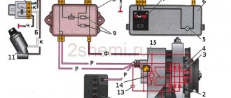
VAZ 2108 generator circuit
The VAZ-2108 generator has a rather massive stator winding, since it uses a large cross-section wire. It is with its help that electricity is generated. The wire is wound evenly over the entire inner surface of the stator into recesses specially provided for this purpose in the magnetic core.
It’s worth talking about the latter separately. The middle part, the generator stator, consists of a series of thin metal plates pressed tightly together. They are often boiled on the outside to prevent separation.
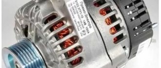
- Alternator. The 37.3701 or 94.3701 series can be installed.
- Negative diode.
- Additional diode.
- Positive diode.
- Alternator warning lamp, also known as battery discharge lamp.
- Instrument cluster.
- Voltmeter.
- Relay and fuse box located in the engine compartment in the compartment between the engine and the vehicle interior.
- Additional resistors built into the fuse mounting block.
- Ignition relay.
- Egnition lock.
- Accumulator battery.
- Capacitor.
- Rotor winding.
- The voltage relay is located in the engine compartment.
Initial excitement
When starting, the initial excitation comes from the battery. Then, when the generator starts working, it itself transfers part of its current to excitation.
When the ignition is turned on, the current from the battery goes to the plus of the generator, from this point through the mounting block it goes to the ignition switch 30\1, through the closed contacts of the ignition switch the ignition relay is turned on. Through the contacts of the ignition relay, from point 30\1 the ignition system and the generator excitation circuit are powered. Through the 5th fuse, the initial excitation current passes into the instrument panel, through the battery discharge lamp, again passes through the mounting block and comes to the connector on the generator. From this connector it goes directly to the voltage regulator. The voltage that reaches point L opens the regulator transistor and the excitation current passes through the brush into the rotor, and from it, through the open regulator transistor to ground.
The current flowing in the circuit from the battery lights up the light bulb, which is an indicator and confirms that the excitation circuit is intact. A small current from this circuit creates a magnetic field in the rotor and the generator is excited.
The generator started working. Exciting the generator through additional diodes
The voltage at the output of the generator quickly increases and becomes higher than the battery voltage, now the generator becomes a source, it begins to charge the battery and power all devices.
The excitation current can be taken from the output of the generator, but in this case this is not the case. The generator output is connected directly to the battery. If you use the generator output for excitation, then there may be such a problem - when the ignition is turned on, if the engine does not start, the battery begins to discharge through the rotor winding along the excitation circuit and, after a few hours, the battery will be completely discharged. This happened with generators of previous releases with conventional diode bridges without additional ones. diodes. (58.3701, G221, etc.)
In this generator, the excitation current is obtained directly from the generator winding. For this, an additional rectifier consisting of three small diodes is provided.
After the initial excitation from the battery, the excitation winding current comes from the additional rectifier. This current flows inside the generator and does not use external circuits and the ignition switch, the circuit is more reliable and accidental discharge of the battery through the excitation winding is excluded.
Technical characteristics of the VAZ 2108 generator
The following generator models are installed on VAZ 2108 cars:
- 3701
- 3701
Technical characteristics of the first:
- The value of the delivered current (at 6000 rpm-1 and a voltage of 13 V) – 55 A — The voltage value – 13.6 – 14.6 V
- Rotor rotation direction – right – Maximum rotor speed – 13000 rpm-1
- Engine/generator gear ratio 1/2.04
Technical characteristics of the second:
- The value of the delivered current (at 6000 rpm-1 and a voltage of 13 V) – 80 A — The voltage value – 13.2 – 14.7 V
- Rotor rotation direction: right
A normally working, serviceable generator of VAZ 2108, 2109, 21099 cars and their modifications produces a voltage in the range of 13.6 V - 14.6 V. This can be visually tracked by a voltmeter on the instrument panel, but it is better to measure the voltage with a voltmeter (multimeter, autotester
Generator 37.3701
1 – clamping sleeve; 2 – bushing; 3 – buffer sleeve; 4 – back cover; 5 – screw for fastening the rectifier unit; 6 – rectifier block; 7 – rectifier block valve; 8 – capacitor; 9 – rear bearing of the rotor shaft; 10 – slip rings; 11 – rotor shaft; 12 – brush connected to terminal “B” of the voltage regulator; 13 – pin “30” for connecting consumers; 14 – output “61” of the generator; 15 – brush connected to terminal “Ш” of the voltage regulator; 16 – terminal “B” of the voltage regulator; 17 – voltage regulator; 18 – stud securing the generator to the tension bar; 19 – impeller; 20 – pulley; 21 – bearing mounting washers; 22 – thrust ring; 23 – front rotor shaft bearing; 24 – rotor winding; 25 – rotor pole piece; 26 – stator winding; 27 – stator; 28 – front cover.
Reasons for failure of the VAZ 2108 generator
Experts believe that the main reasons for the failure of the VAZ 2108 generator are:
- voltage regulator failure;
- damage to the diode bridge (aka rectifier);
- wear of current collecting brushes;
- defects in the charging circuit wires;
- damage or operational wear of the pulley;
- wear of slip rings or commutator;
- short circuit of individual turns on the stator winding;
- bearing failure.
Every self-respecting car enthusiast should understand what causes generator malfunctions most often and how they can be dealt with. It is also necessary not to forget that timely prevention helps to avoid serious problems. Towards the end of the article, we will look at some tips that will help you learn how to test the generator yourself. But let's first learn about the internal structure of the node.
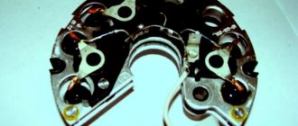
Generator 9402.3701
1 – casing; 2 – output “B+” for connecting consumers; 3 – capacitor; 4 – common terminal of additional diodes (connected to the “D+” terminal of the voltage regulator); 5 – holder of positive diodes of the rectifier unit; 6 – holder of negative diodes of the rectifier unit; 7 – positive diode; 8 – negative diode; 9 – voltage regulator; 10 – back cover; 11 – tightening screw; 12 – front cover; 13 – stator winding; 14 – thrust ring; 15 – front rotor shaft bearing; 16 – pulley; 17 – nut; 18 – rotor shaft; 19 – conical washer; 20 – washer; 21 – rotor pole pieces; 22 – stator core; 23 – bushing; 24 – rotor winding; 25 – rear bearing of the rotor shaft; 26 – bearing sleeve; 27 – slip rings; 28 – brush holder; 29 – stator winding terminals; 30 – additional diode; 31 – pin “D” (common pin of additional diodes).
How to check the voltage of the VAZ 2108 generator
In order to check the performance of the VAZ 2108 generator, you need to perform the following steps:
- Using a voltmeter, diagnose the voltage at the battery terminals. When the engine is running and the generator unit is operating normally, this parameter should be around 13.8-14.5 volts.
- Try placing your palm on the unit body with the engine running, you need to feel the vibration. If there is vibration, you will notice it immediately. Moreover, it may be due to wear of bearing parts.
- It is also necessary to diagnose the tension of the device strap, while the motor must be turned off. Press the strap with your finger - the deflection should be no more than 1.5 cm
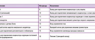
Wiring diagram for windshield wiper and washer
| Position number on the VAZ diagram | Explanation of the position on the diagram |
| 1 | motor with gearbox for windshield wipers |
| 2 | thermobimetallic fuse |
| 3 | electric motor for washer pump VAZ 2108 brand 33.5205 |
| 4 | electromagnetic throttle for windshield washer |
| 5 | relay and fuse block |
| 6 | ignition lock |
| 7 | ignition switch |
| 8 | switch for windshield wipers and washer |
| K3 | windshield wiper switch |
| A | sequence of conditional numbering of contacts in the wiper block |
| B | to terminal “30” of the generator |
| A | 2nd speed cleaner brush |
| b | 1st speed cleaner brush; |
| V | limit switch spring plate |
| g, d | limit switch contact posts |
| C1, C2 | noise suppression capacitors |
| L1, L2 | chokes |
Windshield wipers are available from domestic or Hungarian manufacturers. They are interchangeable in connection and mounting dimensions. The motors with gearboxes of these devices are also interchangeable, although they have some differences in design.
Interchangeability of the VAZ 2108 and VAZ 2106 generator
The idea of replacing a generator on a classic is as old as the history of the car itself, because everyone who installs more bells and whistles on their own car than a weak Chinese radio, the native 42A G-221 is no longer enough for everyone.
True, even those who neglect the hassle of installing a more powerful generator are annoyed by the weak low beam at idle and poor battery charge. Once, an acquaintance fitted me with a 55A generator on a ball and the idea arose about telling you how to install it in our classic.
Having scoured the Internet to find at least something about installing and connecting it to a car, I didn’t find anything useful, a lot of comments like “Plug it in and forget it” or long discussions of professional electricians, but they spoke in a language that would suit a simple Russian to a person, it’s like a Chinese song, nothing is clear.
In this regard, it was decided to write an understandable article for ordinary people in order to help them do this simple procedure of replacing the generator themselves, without any problems and special skills in working with electricity, but with their hands.
It is important to know: There are many alternatives to a standard generator, since with the appropriate skills, means and desire it is possible to install any generator. In the provided article I examine only “economical” VAZ generators from other models, because:
- They are cheaper.
- They are more common.
- They are easier to change - you don’t need to find or make any special fasteners and completely change the electrical system.
How to remove the generator on a VAZ 2108 yourself step by step instructions
In order to remove the VAZ 2108 generator with your own hands, you must perform the following procedure:
- In order to easily remove the VAZ 2108 generator, it is necessary to remove the engine protection.
- During the dismantling process, the VAZ generator must be removed together with the bracket, since its fastening bolt will be impossible to pull out due to the position of the body side member.
- Now disconnect all electrical terminals from the generator
- Then you need to loosen the adjusting nut and the generator mounting nut from below.
- Move the generator forward and remove the loose belt
- Unscrew the bolt and remove the adjusting bar
- We find it at the bottom of the engine compartment (shown in the photo) and unscrew the two bolts securing the bracket.
- Then, carefully pushing down, remove the VAZ 2108 generator
- After repairing or purchasing a new generator, we install it in the reverse order, taking into account the fact that the long bolt securing the bracket should be closer to the generator drive.
- After completing the installation of the VAZ 2108 generator, tension the drive belt
Dismantling the electric generator
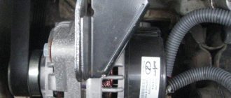
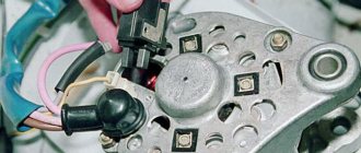
Before removing the generator, you will need to turn off the engine, turn the steering column all the way to the right and look under the hood. On the 2108, the device is located in the lower part, to the left of the engine, next to the cooling radiator. Once you have located the generator, be sure to free the battery terminals before starting work. If you suspect brush wear, you should first remove the charging relay, which is located on the back of the generator housing.
It is secured with two bolts. After unscrewing the hardware and disconnecting the contact plug, you need to inspect the condition of the brushes. If their resource is exhausted, you will need to purchase a new charging relay. This is determined by simply measuring the length of the brush; its size must be at least 4 cm. When the brushes are in working condition, it is enough to fasten the relay back. In case of other problems, you will need to completely dismantle the generator itself.
First of all, you need to disconnect the wiring, which is divided into 2 parts. The first one includes two red wires, they are connected to the back of the generator housing and secured with hardware. The second part consists of one red wire, it is connected to the generator terminal using a plug on the same side of the device. Having disconnected both wiring, you need to dismantle the generator in a certain sequence.
First, the hardware that is attached to the belt tensioner bar (on top of the generator) is untwisted. Then the nut securing the same bar to the motor block is unscrewed. After this, you need to unscrew the nut that secures the generator bracket to the engine block. Next, remove the device belt and unscrew the hardware securing the generator to the car body. After completing these steps, you can remove the generator with a slight movement and begin disassembling it.
How to install and connect a VAZ 2108 generator - step-by-step instructions
Installation of a new generator is carried out in the reverse order. Take a close look at the condition of the bottom bolt. If there is damage to the threads, it is better to replace it.
It will be easier for you to repair the generator later. When installing, pay special attention to belt tension. If it is not tensioned enough, your battery will not charge well. But if you tighten the belt too much, the bearing in the front cover will be destroyed. As a result, you will get an unpleasant whistle when the engine is running. And the reason for this is the appearance of play in the bearing.
The installation of the generator on the VAZ 2108 must be carried out in such a way that even the slightest distortion does not occur.
Video: Removing and installing the VAZ 2108 generator - step-by-step instructions
The principle of operation of the device and its diagram
The electric generator acts as an autonomous source of energy in any car; it is designed to evenly recharge the battery. If the generator fails or wears out, the battery stops receiving the required amount of energy and cannot ensure stable operation of the technical component of the machine.
As soon as its charge runs out, the vehicle stalls. Starting a car after something like this is not the easiest task. To get a visual representation of the operation of the electric generator, you will need its diagram. The VAZ 2108 generator diagram is shown in the figure. All elements that are important in the operation of the device are numbered on it.
- Electric generator.
- Negative diode.
- Spare diode.
- Positive diode.
- Battery discharge control lamp.
- Instrument block.
- Voltmeter.
- Mounting block.
- 100 ohm backup resistors.
- Ignition relay.
- Ignition power.
- Battery battery.
- Capacitor.
- Rotor winding.
- Voltage controller (available only in car models produced before 1988).
VAZ 2108 generator diagram. 1 - generator; 2 - negative diode; 3 - additional diode; 4 - positive diode; 5—battery discharge warning lamp; 6 — instrument cluster; 7 - voltmeter; 8 — mounting block; 9 — additional resistors of 100 Ohm, 2 W; 10 - ignition relay; 11 — ignition switch; 12 — battery; 13 - capacitor; 14 — rotor winding; 15 - voltage regulator
The electric generator on the VAZ 2108 is located under the hood of the car; it operates using a special belt. The main reasons for equipment failure are:
- brush wear;
- charging relay failure;
- diode bridge malfunction;
- rotor shaft bearing stopper.
Characteristics of generators VAZ 2108, 2109
The generator of VAZ 2108, 21081, 21083, 2109, 21091, 21093, 21099 cars is a synchronous, three-phase electric machine, alternating current with electromagnetic excitation.
It has a built-in rectifier (diode bridge) based on silicon diodes and an electronic voltage regulator. In addition, there is a rotor - the rotating part of the generator and a stator - the stationary part. The rotor is driven by a belt from a pulley on the engine crankshaft. On VAZ engines 2108, 21081, 21083 there is a V-belt, on 2111 there is a poly-V belt. A number of cars were equipped with generators made in Bulgaria, Slovenia, and Germany. Their characteristics are similar to domestic generators, but they may differ slightly in design. A 37.3701 generator is installed on VAZ carburetor engines, and a 9402.3701 generator is installed on the 2111 engine. Both generators are similar in design and characteristics, the only differences are in the amount of current supplied (9402.3701 is more powerful).
Technical characteristics of generator 37.3701
— The magnitude of the delivered current (at 6000 rpm-1 and voltage 13 V) – 55 A
— Voltage value – 13.6 – 14.6 V
— The direction of rotation of the rotor is right
— Maximum rotor speed – 13000 rpm-1
— Gear ratio engine/generator 1/2.04
Technical characteristics of the generator 9402.3701
— The magnitude of the delivered current (at 6000 rpm-1 and voltage 13 V) – 80 A
— Voltage value – 13.2 – 14.7 V
— The direction of rotation of the rotor is right
Notes and additions
A normally working, serviceable generator of VAZ 2108, 2109, 21099 cars and their modifications produces a voltage in the range of 13.6 V - 14.6 V. This can be visually tracked using a voltmeter on the instrument panel, or it is better to measure the voltage with a voltmeter (multimeter, autotester...). Based on this, generator malfunctions come down to just two problems:
- the generator does not provide charging current at all , or provides it in a small volume (the voltage is low - the voltmeter needle is in the red zone or close to it);
— the generator produces too much charging current (the voltage is higher than normal, the voltmeter needle points too far to the right).
In the first case, the battery is undercharged and, after some time, starting the engine will be problematic. In the second case, the battery is overcharged and, as a result, its electrolyte boils away (the battery “boils”), the plates fall off, and then the final failure occurs.
It is advisable to have at least the simplest tester in order to diagnose generator malfunctions with a high degree of probability. In addition, based on the instrument readings, you can also draw certain conclusions about the performance of the generator set.
Several articles on our website provide the most common malfunctions of VAZ 2108, 2109, 21099 car generators, recommendations for diagnosing and eliminating them.
In addition, articles on the design and technical data of generators for VAZ 2108, 2109, 21099 cars, their electrical circuits and connection diagrams have been added. We hope that all this will help many car enthusiasts in independently solving problems that arise when operating their cars.
Let's sum it up
Taking into account the above information, it becomes clear that timely noticed and identified breakdowns can not only avoid problems during vehicle operation, but also often increase the service life of the generator.
It is also important, when identifying problems, to carry out all repair work on the automobile alternator efficiently. At the same time, it is important to implement the correct connection during reassembly, which guarantees the full functionality of the repaired or replaced device.
Sources
- https://les74.ru/connecting-generator-vaz-2108-we-connect-and-repair-the-generator-at-the-eight-in-the-home.html
- https://twokarburators.ru/tehnicheskie-harakteristiki-generatorov-2108-2109/
- https://electro-shema.ru/auto-moto/remont-generatora-vaz-2108-2109-21099.html
- https://twokarburators.ru/polnaya-razborka-generator-37-3701/
- https://Vaz-Russia.com/remont-vaz-2108/remont-generatora-na-vaz-2108-vaz-2109-vaz-21099.html
- https://www.tdbate.ru/podkl-generatora-vaz2109.htm
- https://remont-inomarki.ru/generator-vaz-2108.html
- https://zapchasti.expert/generator/generator-vaz-21099-2109-2108.html
- https://provaz2109.ru/elektrika-i-datchiki/generator-vaz-2109-remont-zamena-ustrojstvo.html
- https://KrutiMotor.ru/generator-vaz-2109-ustrojstvo-neispravnosti-remont/
Installing a generator on a VAZ 2108
Finally bought some goodies for my eight to install a generator)))
not a complete set
What I needed:
1. Generator 115A 2. Lower mounting of the VAZ 21082 generator with mounting bolts! 3. Upper fastener for 8-valve valves 4. Alternator belt (this is a separate topic) 5. Plug for genes or small mother
I didn’t install it myself, so I’ll describe everything from the words of the master.
Everything fit without problems, except the belt. To find the one we needed, we traveled all over the city. As a result, it came from 8-mic valves of the first generation. I can’t write more precisely.
After installation, with a sharp acceleration of the gene, the spar caught (perhaps my muzzle was behaving) I had to distort it, but in the end it worked.
I also read that a 330 Ohm 5 W resistor should be installed on the “L” contact, where the gene excitation wire is connected... But I haven’t found it yet.
Heater fan motor connection diagram
| Position number on the VAZ diagram | Explanation of the position on the diagram |
| 1 | Relay and fuse block for VAZ 2108 |
| 2 | ignition switch |
| 3 | additional resistor |
| 4 | electric heater fan motor VAZ 2108 brand 45.3730 |
| 5 | heater electric motor switch |
| A | to terminal "30" magneto |
Device Description
Before we tell you how to check and repair the 2108 generator yourself, we suggest that you familiarize yourself with basic information about the device. First, let's look at the principle of operation and device. A detailed diagram of the device is shown in the photo.
Principle of operation
The purpose of the unit is to provide electrical appliances and vehicle equipment with energy, and first of all we are talking about the battery. If the mechanism breaks down, the battery stops charging normally, and due to lack of voltage, the battery does not allow the operation of electrical equipment. When the device's charge runs out, the car will simply stall, and it will not be so easy to start it later.
Designation of mechanism components in the diagram
The system is powered by the rotation of the pulley on which the belt is installed. The VAZ generator pulley receives mechanical force from the crankshaft through a belt. The latter can be either wedge or polywedge.
Device components
We will not fully list what components the generator on a VAZ 2108 car or the mechanism on a classic consists of, since the device of different generators is almost identical.
Let's look at the main elements:
- A diode rectifier used to convert alternating current to direct current.
- The generator belt, which transmits power.
- The pulley on which the belt is mounted.
- Brush unit.
- A voltage regulator relay, the purpose of which is to protect the battery from overvoltage.
- A light bulb that is displayed on the dashboard. It is used to notify the driver about malfunctions in the operation of the device (the author of the video is the Engine Repair channel! And interesting!).
Replacement and removal of the electric generator
The generator on a VAZ car is removed either for complete replacement in case of failure or to carry out repair work to replace faulty parts. To perform dismantling, prepare a standard set of tools; it is advisable to drive the car into the inspection hole.
- Disconnect the battery.
- Remove the protective rubber cap from terminal “30” and unscrew the nut and remove it from the wire stud.
- Disconnect the block with wires from the generator connector.
- We loosen the tightening of the generator to the adjusting bar, then lift it all the way up to the cylinder block and remove the belt from the pulleys.
- Completely unscrew the bolt securing the adjusting bar to the cylinder block, then from the bottom of the car unscrew the 2 bolts securing the lower bracket to the block and remove the generator, pulling it out of the engine compartment.
Source
How to check the generator?
To check the functionality of the unit in your car, you need to follow these steps:
- Using a voltmeter, diagnose the voltage at the battery terminals. When the engine is running and the generator unit is operating normally, this parameter should be around 13.8-14.5 volts.
- Try placing your palm on the unit body with the engine running, you need to feel the vibration. If there is vibration, you will notice it immediately. Moreover, it may be due to wear of bearing parts.
- It is also necessary to diagnose the tension of the device strap, while the motor must be turned off. Press the strap with your finger - the deflection should be no more than 1.5 cm (video author - Vyacheslav Lyakhov).
Electrical diagram of the rear window heating system
| Position number on the VAZ diagram | Explanation of the position on the diagram |
| 1 | Relay and fuse box |
| 2 | rear window heating connector |
| 3 | ignition switch |
| 4 | rear window heating switch; |
| 5 | rear window heating connection control |
| 6 | rear window heater |
If the glass does not warm up when the heating is connected, you need to check fuse F4, the wires and their connections, as well as the switch and relay 2.
If the rear window heater breaks down, the manufacturer recommends replacing the entire glass, but now the retail chain has special kits for repairing broken heater threads, which consist of the necessary components, tools and instructions for use.
Typical malfunctions and methods for their elimination
To prevent unit failure, it is necessary to ensure its high-quality and timely maintenance. As you can see from the photo of the diagram, the unit consists of many different components, so the likelihood of it breaking due to improper maintenance is quite high.
So, in what cases is a VAZ generator repaired:
- The indicator light on the dashboard does not turn on, although the unit and all equipment are working normally. Most likely, the problem is an open circuit or burnout of the indicator itself. In some cases, the reason is poor contact of the diode with the wiring; in this case, you only need to clean the contacts of the connection connector.
- The indicator on the tidy, as well as the instruments themselves on the control panel do not work. Apparently, the reason for this is the failure of the safety element, which will need to be replaced. Also, the reason may be a break or unsoldering of the wiring.
- The warning light comes on after the engine starts, but it disappears after the driver presses the gas. The essence of the problem lies in the fact that the generator unit is not excited at low engine speeds; in most cases, this is due to the desoldering of the resistor elements in the block. Conduct their diagnostics and, if necessary, solder them again.
- Another malfunction is that the indicator continues to light when the engine is turned on, while the voltmeter needle on the dashboard is in the red zone. In this case, there may be several reasons for the problem. First of all, it could be the strap slipping - you need to check it and, if necessary, tighten it. Also, the reason may be a short circuit or breakdown in the diode elements of the winding; much less often, a malfunction occurs when the voltage regulator fails.
- Another sign is that the indicator does not light up when the engine is running, but the voltmeter needle on the dashboard is in the red zone. In this case, you first need to diagnose the presence of contact between the regulator connector and the brushes. If the contact is normal, then check the brushes (they may freeze), as well as the slip rings; for the latter, the problem of oxidation is relevant. In addition, the cause of the problem may lie in the failure of the voltage regulator; usually we are talking about a break in the wiring between the contact and ground. The same symptoms appear in the event of a short circuit on the positive valves of the rectifier element.
- When the engine is running, the voltmeter needle is located in the red zone - this symptom indicates damage to the voltage regulator. In particular, we are talking about a short circuit that can occur between ground and also contact Ш. The problem can only be solved by replacing the regulator.
- If the unit is significantly louder than usual, there may be several reasons for this. First, you should check the functionality of the bearing elements, as well as the tightness of the pulley nut. In some cases, the loud operation of the unit is due to the creaking of the brushes. The brushes themselves may be of poor quality, but it is possible that the problem is dust getting on the slip rings.
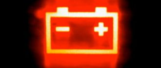
The light bulb is a convenient indicator that allows you to monitor the operation of the generator.
When the ignition is turned on, the light bulb lights up and excitation current flows through it to initially excite the generator. The light bulb limits this current by its resistance to 100 mA. This current is sufficient for the first excitation impulse, then the generator itself begins to energize the excitation winding through an additional rectifier.
The circuit through the light bulb remains closed after the generator starts operating, but if the engine is not running and the ignition remains on, the battery discharge through this circuit is unnoticeable, because the current is specifically limited by the light bulb (the light is on - this is a request to turn off the ignition)
The light bulb, when the generator is running, receives the plus from the additional diodes, and on the other side the positive from the output of the generator continues to act, it turns out that the same plus acts on the light bulb on both sides, in this case the voltage is zero and the light goes out.
Thus, if after starting the engine the light goes out, then everything is fine and the generator is working.