Ignition timing is a very important parameter on which the normal operation of the engine depends. If this timing (ignition timing) is set incorrectly, the engine will start poorly, operate unstably at idle, not develop full power, overheat and consume gasoline unnecessarily. In addition, if the ignition timing is too large (“early” ignition), detonation may occur - a very dangerous phenomenon, often leading to emergency engine damage.
In a contactless ignition system, ignition timing (ignition timing) can only be set using a strobe light
A strobe light is available to almost every motorist, as it can be purchased at almost every auto parts store at an affordable price.
The ignition timing is checked and set at engine idle (at a crankshaft speed of 820–900 rpm). The angle should be within 1°± 1° BTDC.
Check the ignition timing using the mark on the flywheel and the scale of the crankshaft rear oil seal holder (the rubber plug has been removed). When the marks on the flywheel are combined with the middle division (notch) on the scale, the piston of the first cylinder is installed at TDC. One division on the scale corresponds to 2° of crankshaft rotation.
The ignition timing can also be checked and set using the marks on the generator drive pulley and the front camshaft drive belt cover. The long mark corresponds to the installation of the first cylinder at TDC, the short mark to the ignition advance by 5° of crankshaft rotation. These marks are used to set the ignition timing on the stand.
1. For ease of operation, remove the air filter (see “Removing and installing the air filter”).
2. Disconnect the hose from the vacuum regulator.
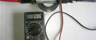
3. To check the ignition timing, connect the “+” clamp of the strobe to the “+” terminal of the battery, and the “ground” clamp of the strobe to the “–” terminal of the battery.
4. Remove the tip of the high-voltage wire from the spark plug of the first cylinder and connect it to the strobe sensor in accordance with the instructions included with the strobe.
5. Remove the rubber plug from the clutch housing hatch.
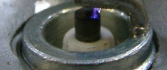
6. Start the engine and direct the flashing strobe light into the clutch housing hatch.
The stroboscopic effect is based on the inertia of human vision. With frequent alternation of bright flashes, the eyes see objects only at the moment of the flash. If the frequency of repetition of flashes coincides with the frequency of rotation of an object, this object appears motionless. When adjusting the ignition timing, the flywheel with a mark on it appears motionless.
Illuminated by strobe flashes, rotating engine parts (crankshaft and generator pulleys, cooling system radiator fan), as well as the generator drive belt, appear stationary or slowly moving. Be careful not to get injured.
7. When the ignition timing is correctly set, mark 1 on the flywheel should be between the middle division 2 and the previous division 3 of the scale. Otherwise, it is necessary to adjust the ignition timing.
Video “Instructions for replacing the ignition coil”
Learn more about how to replace the ignition coil in Oka with your own hands from the video below (author - Butovsky Gulyak channel).
Good day!
Some time ago I noticed that my Oka periodically shoots at the silencer. At the same time, I have never heard detonation on it, except very briefly when starting off very sharply. I noticed that the distributor was turned 1 division counterclockwise relative to its average position (i.e., 8 degrees along the crankshaft, as they say in the book). I turned the distributor approximately 1/4 notch clockwise (that is, I set it to 2 degrees earlier). It became noticeably easier to move away (it became almost as easy as driving a UAZ truck - the car stopped either stalling or jerking sharply), and it seemed like the traction at the bottom increased. and the engine stopped firing from the muffler.
Maybe try to tighten it up some more?
I heard that on engines 2108/09 (and therefore on Oka, probably) detonation is not as audible as on other engines (Volga, UAZ, Lada, etc.). And in the instructions they write (unlike the UAZ) to adjust not by detonation, but by strobe (which I don’t have, of course).
How to set the ignition correctly on Oka?
Thanks for any answers!
Setting the ignition “by ear” We set the sensor firmly to “+”, not paying attention to any risks and so on. We find a flat section of the road, accelerate on it to 60-65 km/h (if the jerker is 1111 - up to 55-60 km/h), stick the fourth gas pedal firmly to the floor. Engine detonation will be clearly audible with a characteristic metallic tinkling sound (they still ignorantly say that “fingers are knocking”). We stop, turn the sensor a little to minus, and repeat the ride. The goal is to ensure that when the pedal is pressed to the floor, the detonation knock is practically one or two “dings” and immediately stops. I drove with this setup for several years and didn’t know any grief.
not having an ear for music by the way Teapot
Ignition timing
Valve?? Maybe the so-called “fingers”? (although it’s not the fingers that are knocking there, but that’s what they call it).
This means it’s not normal if you don’t deliver it earlier. There should be some margin for installation “earlier”. And the marks are not true! Whether on the Zhiduli, or on the Oka, I saw the same picture everywhere, that the mark was not exactly there, but as if half a tooth apart. So on the Oka, this situation is precisely the decisive one in the question of why the DMI (distributor on the Oka) is stuck in place and the ignition is not done earlier. According to your letter, it turns out that the mark was moved by a tooth, but the DMI was not touched at all and they did not even try to ignite it before. Well, there are some inconsistencies in the message.
..For example. That is, it was not possible to do the ignition earlier. Are you sure you’ve been to a service station with the masters? Or do they also have “valves that don’t knock” when you press the gas sharply?
Any Chinese knows the situation in domestic cars about “half a tooth”. Whether on the Six or on the Oka, this problem exists everywhere. We always puzzled over how to leave it all?! So in Oka this issue is solved simply - in a position where the distributor has a reserve to make the ignition earlier than 4 degrees before TDC. That is, if before the transfer the mark did not coincide by half a tooth BEFORE, then it will not coincide by half a tooth AFTER. Or vice versa (I’ve forgotten now, and I’m too lazy to imagine it in my head - but the general meaning is clear). The lead for OKI with a 13m engine (0.75l) is 4 degrees before TDC. It’s 6-7 degrees for me and I fill it with 95th gasoline - it’s been flying for five years now, but 92nd gasoline is contraindicated, in about the same way as using 80th instead of 92nd.
Have you ever ridden on the Oka River before this? Maybe you got into a three-liter Pradika, or from the same two-liter Corolla. There you just put the pedal to the floor and no hill is scary. And on the Oka you also need to know how to drive on the highway. The most “fun” gears on the Oka are 1 and 2. In the third, the engine is already noticeably weakening, and it’s generally better to engage fourth at least 70 mph. On a long hill only from acceleration, or you will inevitably have to stick in a third one. Especially when there is a family in the cabin and 2 bags of potatoes in the trunk.
How to set the ignition on a walk-behind tractor
Let's look at how to adjust the ignition of a walk-behind tractor. The walk-behind tractor ignition system is quite simple
Before installing the ignition, it is important to make sure that this design produces a spark, which in turn will ignite the fuel liquid located in the internal combustion chamber
In order not to turn to specialists for trifles and save your money, you need to understand how the ignition and ignition coil settings are adjusted. Let's look at how to set the ignition on the MB 1 and MB 2 walk-behind tractor.
You can set the ignition using a spark. It is necessary to turn the crankshaft so that the marks of the pulley and the gas mechanism coincide. The slider distributing the gas flows should point to the high-voltage wire of the cylinder.
You need to slightly unscrew the nut that changes the position of the mechanical structure that determines the moments of the high-voltage pulse.
Then you need to remove the high-voltage wire from the system cover. He is at its center. Then place the contacts at a distance of 5 mm from the cultivator.
After this, turn on the ignition.
Next you need to turn the mechanical structure, which determines the ignition timing, clockwise to the 200 mark
Carefully turn the above structure in the other direction
A spark occurs between the central high-voltage wire and the ground of the cultivator. After this, you need to quickly tighten the breaker nut to prevent ignition.
You can set the ignition by sound. If the owner has fairly good hearing, then this method of checking and adjusting the ignition is quite suitable. In other words, this is a non-contact test of candles.
The non-contact method involves the following procedure:
- First you need to start the engine.
- Then you need to loosen the distributor a little.
- Rotate the breaker body slowly on both sides.
- The mechanical structure, which determines the moment of spark formation, must be strengthened in the state of greatest power and the greatest number of revolutions.
- Next, listen carefully. When turning the intermittent system, clicks should be heard.
- After all the steps taken, you need to tighten the distributor nut.
The strobe method works like this:
- First you need to warm up the engine.
- After this, attach the strobe light to the walk-behind tractor.
- A sensor that responds to sound must be connected to the high-voltage wire of the cylinder.
- Remove the vacuum hose and plug it.
- The strobe light will emit a light that should be aimed at the pulley.
- Start the unit engine again and leave it idling.
- Turn the distributor.
- Fasten as soon as the pulley mark points to the mark marked on the cover of the walk-behind tractor.
- Tighten the breaker nut.
The above describes how to check the ignition coil. When installing the system, it is advisable to use the instructions, especially for owners who are encountering this for the first time.
Adjusting the reel is not a difficult task.
About the engine
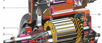
For these models, engines 2108 and 21083 were taken as the basis. They are 2-cylinder engines with an in-line vertical arrangement of cylinders. The camshaft is installed in the cylinder head. The working volume is 649 cm 3 and 749 cm 3. The increase in volume is obtained by increasing the diameter of the pistons from 76 mm to 82 mm. The cylinder blocks of these engines, heads, flywheels, and pulleys are different.
Many spare parts are unified with their 4-cylinder variants. The power supply system is carburetor, but with changed calibration data. In 1990, the timing belt on the power unit was replaced. If the previous product had semicircular teeth, then on the new one they began to have a trapezoidal shape with a groove at the top of the tooth. The pulleys were changed to match the tooth profile, but the belts themselves are interchangeable; you can use both new and old parts.
It is possible to obtain maximum efficiency from using an internal combustion engine only with the correct adjustment of the valve timing. There are marks on the timing drive for this purpose. One of them is the protrusion on the rear cover for the drive belt protection, which should coincide with the mark on the camshaft pulley. The second mark is located at the bottom of the cylinder block, and it coincides with the mark on the crankshaft pulley. The piston of the first cylinder should be at top dead center at this time.
Are the valves bending?
This question worries many owners, since after such an “incident” a costly overhaul of the power unit will follow. Mechanics know of cases where, after the pistons met the valves, in addition to bent valves, the piston heads were damaged and the guide bushings in the cylinder head were destroyed. The engine, based on the VAZ 21083 engine, is free from such shortcomings. The pistons of this internal combustion engine have recesses that prevent the valve head from meeting the upward-moving piston.
This problem can occur in two cases:
- Cutting teeth on the timing belt.
- The alignment marks on the engine being repaired are not aligned correctly.
To avoid this, you should carefully study the process of replacing the belt, or seek help from service center specialists.
Checking and adjusting ignition timing
Ignition timing is a very important parameter on which the normal operation of the engine depends. If this timing (ignition timing) is set incorrectly, the engine will start poorly, operate unstably at idle, not develop full power, overheat and consume gasoline unnecessarily. In addition, if the ignition timing is too large (“early” ignition), detonation may occur - a very dangerous phenomenon, often leading to emergency engine damage.
In a contactless ignition system, ignition timing (ignition timing) can only be set using a strobe light
A strobe light is available to almost every motorist, as it can be purchased at almost every auto parts store at an affordable price.
The ignition timing is checked and set at engine idle (at a crankshaft speed of 820–900 rpm). The angle should be within 1°± 1° BTDC.
Check the ignition timing using the mark on the flywheel and the scale of the crankshaft rear oil seal holder (the rubber plug has been removed). When the marks on the flywheel are combined with the middle division (notch) on the scale, the piston of the first cylinder is installed at TDC. One division on the scale corresponds to 2° of crankshaft rotation.
The ignition timing can also be checked and set using the marks on the generator drive pulley and the front camshaft drive belt cover. The long mark corresponds to the installation of the first cylinder at TDC, the short mark to the ignition advance by 5° of crankshaft rotation. These marks are used to set the ignition timing on the stand.
1. For ease of operation, remove the air filter (see “Removing and installing the air filter”).
2. Disconnect the hose from the vacuum regulator.
3. To check the ignition timing, connect the “+” clamp of the strobe to the “+” terminal of the battery, and the “ground” clamp of the strobe to the “–” terminal of the battery.
4. Remove the tip of the high-voltage wire from the spark plug of the first cylinder and connect it to the strobe sensor in accordance with the instructions included with the strobe.
5. Remove the rubber plug from the clutch housing hatch.
6. Start the engine and direct the flashing strobe light into the clutch housing hatch.
The stroboscopic effect is based on the inertia of human vision. With frequent alternation of bright flashes, the eyes see objects only at the moment of the flash. If the frequency of repetition of flashes coincides with the frequency of rotation of an object, this object appears motionless. When adjusting the ignition timing, the flywheel with a mark on it appears motionless.
Illuminated by strobe flashes, rotating engine parts (crankshaft and generator pulleys, cooling system radiator fan), as well as the generator drive belt, appear stationary or slowly moving. Be careful not to get injured.
7. When the ignition timing is correctly set, mark 1 on the flywheel should be between the middle division 2 and the previous division 3 of the scale. Otherwise, it is necessary to adjust the ignition timing.
8. To set the ignition timing, loosen the three nuts securing the spark timing sensor.
9. To increase the ignition timing, turn the sensor housing clockwise (the “+” mark on the flange of the sensor housing is towards the protrusion on the auxiliary drive housing. In this case, one division on the flange corresponds to 8° of crankshaft rotation). To reduce the ignition timing angle, turn the sensor housing counterclockwise (the “–” mark on the flange of the sensor housing is towards the protrusion on the auxiliary drive housing).
10. Tighten the sensor mounting nuts, check and, if necessary, repeat the ignition timing setting.
11. Connect the hose to the vacuum regulator.
source
Setting the advance angle
Setting the ignition timing is the only operation that is performed in the ignition system.
A strobe light is used to set the angle correctly. The technology for performing the work is not complicated. The algorithm of actions is as follows:
- We connect the strobe to the power source and the tip of the spark plug of the 1st cylinder (according to the instructions for the device);
- Remove the plug from the inspection window on the clutch housing;
- We start the engine (it should be idling);
- We direct the beam of light from the strobe into the viewing window;
- We determine the position of the marks (with the angle correctly set, the mark on the flywheel at the moment the strobe light beam flashes should be located between the central and rear marks on the crankcase);
- If the marks are not positioned correctly, make adjustments. To do this, loosen the bolts securing the spark moment sensor and rotating it around its axis until the marks match;
After adjustment, tighten the sensor fasteners, turn off the engine, disconnect the strobe light and replace the plug.
Modernization of the ignition system of VAZ – 1111 “Oka”
As you know, Oka cars are equipped with a rather imperfect 2-spark ignition system (similar to the options installed on some motorcycles). In general, the use of such a principle of organizing the ignition system cannot be called particularly flawed, however, due to the design features and the not very high quality of individual elements, it has a number of significant disadvantages. In particular, Oka owners are well aware of the existence of problems with starting these cars in winter (even a slightly “supercharged” battery simply cannot cope with maintaining a “push-pull” spark). The state of insulation between the high-voltage and low-voltage circuits of standard double-spark coils does not stand up to criticism either, as a result of which they very quickly fail due to moisture ingress and in damp weather. And, finally, such an unpleasant phenomenon as occasional “shots” in the muffler is also a consequence of the use of a two-spark ignition system - when an incompletely burned mixture is squeezed out by a piston into the intake manifold and, with the valves open, is ignited there by a “non-working” spark.
Be that as it may, the need to modernize the ignition system of the VAZ-1111 Oka is beyond doubt, and currently three main methods are most widespread:
In general, any of these methods allows you to achieve a certain positive result, although each of them is not without some disadvantages. So the first method reduces the overall reliability of the system due to the use of additional elements, namely a high-voltage distributor and several high-voltage wires. The second method is simply to use a more reliable version of the same two-spark system (if you can find decent equipment). Finally, the third method does not eliminate the problem of an “unnecessary” spark and is associated with energy expenditure on the second ignition coil.
Based on the above, it makes sense to carry out a more original and effective modernization, namely, leave only one curtain in the original spark sensor and add a pair of Hall sensors to the system, spaced 180 degrees apart. In other words, it is proposed to implement the third option, eliminating its shortcomings by providing ignition in each of the cylinders using Hall sensors.
Preparatory work
Implementation Features
To ensure normal operation of the system, the hall sensors must be of the same type (from the same batch), otherwise the direction of the magnets will be disrupted and, as a result, the DMI curtain will be remagnetized. Simply put, you will have to abandon the original sensor.
Power wiring for plus 12V on the relay (in the standard version, blue-black) is carried out with a wire with a cross-section of at least 4 sq mm, while for switches a stranded wire of 2.5 mm is sufficient. It is better not to use standard wiring as there are significant losses on it.
For the signal part, you can take a shielded multi-core cable with a core cross-section of 0.2 mm (the screen will help get rid of interference).
The main difficulty in manufacturing a modernized ignition system is the need to accurately position the Hall sensors on the installation platform. The main problem is that the sensors must be installed with an accuracy of 0.1 mm opposite each other (relative to the circle passing through the centers of their slots). In any case, the sensor mismatch should not exceed 1 degree of crankshaft rotation. If this condition is not met, a significant drop in engine power is observed. For the same reasons, you should ensure that all elements of the system are securely fastened.
The ignition timing is set according to the standard method.
Tags ignition VAZ, OKA VAZ-1111
Design
The ignition system of the VAZ Oka consists of only seven main elements:
- Auxiliary relay;
- Egnition lock;
- Circuit breakers;
- Switch;
- Spark moment sensor;
- Coil;
- Candles;
All elements are connected to each other by wiring.
Using the ignition switch, the driver controls the power supply to the system from a source - the battery, while the voltage passes through the auxiliary relay and fuses. The lock has three positions - “0”, in which all electrical consumers are turned off, “1” - voltage is supplied to the ignition system and a number of other devices, and “2” - current is supplied to the starter. This switching sequence ensures that the ignition system is activated at the moment the engine starts.
Spark torque sensor
The spark timing sensor is one of the main ignition components, since it sets pulses that are subsequently converted into a spark discharge between the spark plug contacts. This sensor is driven by the camshaft, which allows you to accurately set the timing of the spark in the cylinders.
The main working elements of the unit are the Hall sensor and a special screen with slots mounted on the drive shaft interacting with the camshaft. The interaction of these elements leads to the emergence of control impulses.
The sensor not only sets pulses, it also “adjusts” to the operating conditions of the motor, adjusting the advance angle depending on the operating conditions of the motor (speed, load).
The adjustment is carried out by two regulators - vacuum and centrifugal, included in the design of the spark generation moment sensor.
Until 1989, Oka used a sensor of type 55.3706, and after that it was replaced by model 5520.3706.
Switch
The switch acts as a circuit breaker for the primary winding of the coil, using control pulses coming from the spark sensor. Circuit interruption in the switch is performed by the output transistor. The switch is completely electronic, without any moving elements, so the ignition system is contactless.
Several types of switches were installed on the VAZ-1111 and 11113 - 36.3734, 3620.3734, as well as HIM-52. The switch is installed in the engine compartment near the engine panel. It is secured with two bolts, so replacing the switch is quite simple.
Coil
Oka received a two-terminal ignition coil, which made it possible to remove the distributor from the design.
It is noteworthy that the high voltage in this coil is supplied simultaneously to both spark plugs. Moreover, due to the offset strokes in the engine cylinders, only one spark discharge is working, the spark on the second spark plug is the so-called “idle”.
The standard coil on the Oka is type 29.3705, but it has an analogue that is suitable for use on a small car - 3012.3705.
Wires, spark plugs
All wiring consists of low and high voltage wires. The first ones are used to connect all the components up to the coil. These are ordinary wires of small cross-section, which is quite sufficient, since the voltage in the circuit up to the coil is low.
High voltage wires are used to connect the coil terminals to the spark plugs. For ease of connection, lugs are installed at the ends of these wires.
Recommended for use on Oka are spark plugs of type A17DVR - with an extended thread and an interference suppression resistor, as well as their analogues.
Oka gas distribution mechanism
If you compare old VAZ classic engines with a timing chain drive, you will notice significant differences in the design of the drive. The bulky metal chain was replaced with a timing belt. The design of the cylinder block has become shorter and lighter, since the opening for the chain in the timing drive mechanism has disappeared. The designers changed the principle of opening valves, it became simpler. If on old engines the camshaft cam pressed on the valve stem through the rocker arm, now it acts on it through the adjusting washer. The thermal gap is set on a cold engine by selecting a washer of the required thickness. Manufacturers make them in different sizes, the values of which are marked on the ends of the washer. If the driver adjusts the thermal gap independently, he will have to purchase a certain number of such washers, which is not always economically feasible.
The design of the timing mechanism drive is such that the belt drives the pump in the Oka engine cooling system. Often it is because of the breakdown of this pump that the toothed belt drive fails. Therefore, car manufacturers recommend that the belt drive and pump in the engine cooling system be replaced at the same time
When inspecting, you should pay attention to the condition of the tension roller in the timing mechanism.
Belt replacement procedure
The process of replacing a timing belt on Oka is not very difficult. If you carefully study the process before doing this, you can do it yourself. The work can be done on any level surface.
Before starting the operation, install wheel chocks under the rear wheels and tighten the hand brake cable. The front wheels are turned to the right as far as possible (all the way), and the battery is disconnected. The further procedure will be something like this:
Checking the ignition angle while the vehicle is moving
It is best to check the functionality of the ignition system after any adjustment while driving. This is due to the design features of the distributor and the octane number of the gasoline used. It happens that the ignition angles set according to the marks do not provide sufficient dynamics and throttle response. Adjusting by ear according to the beginning of detonation will help:
- We accelerate the car to a speed of 45-50 km/h on a flat section of the road;
- We turn on direct transmission (fourth on the VAZ 2106) and press the gas pedal all the way;
- A characteristic ringing sound (detonation) should appear, which will disappear after 2-3 seconds, and the acceleration will be smooth and powerful without failures;
- If detonation does not disappear throughout the entire acceleration, then the ignition angle is “early”;
- The complete absence of ringing and sluggish dynamics indicate a delayed spark in the cylinders;
- We adjust the position of the distributor in place, turning it by 3-5 degrees;
- When the adjustment is completed, the position of the distributor body relative to the block is marked with a mark or paint.
Ignition adjustment work should be carried out regularly. The service interval for a simple contact ignition system is 15,000 km, for an electronic one - twice as long. The condition of the spark plugs and high-voltage wires is also regularly checked. All setup operations can be easily done independently; a garage is not needed for this. The skill of independently repairing the ignition of a VAZ 2106 will always come in handy on a long journey or in winter, when problems arise with starting.
vote
Article rating
How it all works
The principle of operation of the ignition system is as follows: after turning the key to position “1” el. Energy from the battery is supplied to the ignition system components through the lock, fuses and auxiliary relay. In this case, high voltage pulses are not generated, since the spark torque sensor is not yet operational.
After activating the starter, the timing drive begins to rotate the camshaft, and accordingly the sensor shaft - the Hall sensor begins to interact with the screen, due to which control pulses are created.
Arriving at the commutator, these pulses interrupt the power supply circuit of the coil winding. When the power circuit is broken, a high voltage pulse is induced in the coil, which is transmitted through high-voltage wires to the spark plug, which leads to the formation of a spark between its electrodes.
Related link:
Generator OKA
Installing the ignition on a VAZ (“classic”)
They are equipped with one of two types of ignition. The first is contact: here the opening is carried out by turning the distributor shaft (mechanical method). The second type of ignition is electronic, non-contact: it uses a Hall sensor, which determines the time of spark formation.
How the ignition system works
When the piston reaches the TDC position, it compresses the combustible mixture with maximum force. At this time, a high voltage is formed in the coil. From the distributor cover it is supplied through high-voltage wires to the spark plugs, where a spark is formed that ignites the mixture. When the crankshaft speed increases, the ignition timing changes. This procedure is “carried out” by a vacuum regulator (attached to the ignition distributor), connected via a tube to the intake manifold. As a result, optimal power is achieved in any engine operating mode.
Symptoms of a problem
- the engine cannot be started or it runs extremely unstable (stalls);
- deterioration in driving dynamics: sluggish acceleration;
- increased fuel consumption;
- pops in the muffler;
- vibration during operation of the power plant.
How to set the ignition timing with a strobe light
This is a fairly accurate method that does not require dismantling the valve covers and distributor. The procedure takes literally a few minutes and consists of the following steps:
- with the engine turned off, loosen the nut securing the ignition distributor (key 13), noticing its original position;
- clean the front motor cover (under the pulley) from dirt so that the marks are visible (one long, two shorter);
- Connect the negative terminal of the strobe to the engine ground, the positive terminal to the ignition coil (terminal or nut on the side), fix a separate clamp on the high voltage wire of the 1st cylinder.
- start the engine and point the strobe light at the pulley;
- the mark on it should coincide with the central tide on the front cover of the BC if A80 gasoline is used, and with the longest outer one if the fuel is AI92;
- if this is not the case, smoothly turn the distributor until a match occurs.
How to set the ignition on a car using a light bulb
If you don’t have a strobe light, you can use a regular car light bulb to which you need to solder a couple of wires. A voltmeter will also work. Adjustment steps:
- Unscrew the spark plug from cylinder 1;
- rotate the crankshaft (with a handle or a wrench) until compression begins: this can be determined by inserting a screwdriver into the spark plug hole and waiting until the piston touches it and begins to move down;
- at the same time look at the marks on the engine cover: one of them (this depends on the octane number of gasoline) should align with the mark on the pulley;
- remove the PP cover: the rotor should “look” towards the 1st cylinder;
- slightly unscrew the nut securing the distributor;
- Fix one wire from the light bulb to the body, the second to the PP contact, which is located on the side;
- turn on the ignition without starting the engine: if the ignition timing is correct, the light will not light up;
- if it is on, turn the distributor until it goes out;
- secure the distributor.
How to adjust the ignition by ear
That is, you can achieve the correct setting without tools at all: you only need a 13 key. The method is effective, but only if the valves are adjusted correctly and the carburetor is in good working order:
- warm up the power unit to operating temperature;
- loosen the distributor fastening with a 13mm wrench and slowly turn it clockwise and counterclockwise;
- achieve smooth, stable engine speed at idle (800-850 rpm);
- fix the PP in the found position.
How to check correct ignition while driving
To do this, you need to accelerate the car to a speed of 50 km/h in fourth gear and sharply press the gas pedal. If the ignition angle is set correctly, a detonation ringing will appear, disappearing after a couple of seconds. If it does not disappear, the ignition is too early.
If there is no detonation at all, and acceleration is sluggish, this indicates late ignition of the mixture in the cylinders. In such cases, stop the car and turn the RR 3-5 degrees, then accelerate again. Repeat the operation until you achieve the desired result.
Operation of the Oka car ignition system and possible problems with it
To ensure normal engine starting in any weather, many different mechanisms and elements are used. But they are all combined into one system - the ignition system (I). We will tell you more about the SZ for the Oka car below. What functions does the Oka ignition coil perform, what malfunctions are typical for SZ in general, and how to set the advance angle - read below.
Contactless SZ scheme on Oka
Before we talk about how to set and adjust the ignition on the Oka with your own hands in accordance with the diagram, let's understand the features of the SZ.
The ignition system on any car includes several different components, the main ones:
- Spark timing controller. This device is equipped with vacuum and centrifugal regulators. The device is designed to ensure the timing of spark formation, taking into account its standard installation, the number of engine revolutions, and the load on the motor. The signal reading procedure is based on the Hall effect.
- The switching device is designed to open the supply circuit of the primary winding of the short circuit, thus converting control signals into current pulses. When the ignition is activated, the connector of the switching device must not be disconnected under any circumstances, since this will lead to damage not only to this unit, but also to other elements of the SZ.
- Coil. In the ignition systems of Oka cars, in accordance with the diagram, a two-terminal short circuit with an open or closed magnetic circuit is used.
- Candles. This element is designed to transmit a high-voltage pulse, which contributes to the ignition of the combustible mixture in the cylinders of the internal combustion engine. The service life of spark plugs is about 10 thousand km, but this figure can be changed upward in accordance with the specifics of the spark plugs themselves. Or to a lesser extent, if for some reason the service life of the spark plugs is reduced.
- High-voltage cables designed to connect spark plugs to a distributor. In Oka, high-voltage circuits with distributed resistance are used. Do not touch them while the engine is running, as this may cause serious injury. It is also prohibited to start the power unit if the high-voltage circuit is broken (the wires may be broken or crushed, or the insulation on them may be damaged). If the insulation is broken, then other elements of the system may fail in accordance with the diagram.
- Egnition lock. According to the diagram, the lock is designed to start the engine by supplying voltage to an additional relay when the key is turned (video author - Nail Poroshin).
Typical system malfunctions
Among the malfunctions of the SZ, the following should be highlighted:
- Coil failure. This problem doesn't happen often, but it can happen nonetheless.
- Distributor failure. You can read more about distributor malfunctions, as well as troubleshooting, here.
- Spark plugs are worn out or have carbon deposits on them. This problem is relevant for many of our compatriots. Read about the reasons why soot appears and what ways to eliminate this problem exist in this article.
- Malfunction of high-voltage wires. The wires may be broken (broken) or their insulation may be damaged. Operating a car with such a problem is not allowed.
- Broken ignition switch. Wear on the inside of the lock will result in the driver being unable to start the engine with the existing key. Replacing the lock cylinder will solve the problem (the author of the video is Mikhail Burashnikov).
Ignition of the Eye
When designing the small car VAZ Oka 1111 and 11113, many components and mechanisms were “borrowed” from other VAZ models, which made it possible to reduce the cost of car production and speed up the start of production.
But the designers had to significantly rework some components in order to adapt them to the features of the Oka engine. One of these components is the ignition system. When creating the ignition system, the designers used modern developments of those years. The VAZ Oka received a non-contact ignition system. At the same time, the features of the power plant made it possible to somewhat simplify the system and reduce the number of components, which had a positive impact on the reliability of this component of the power plant.
OKA car gas distribution mechanism
Maximum engine efficiency can be achieved only by correctly adjusting the valve timing. This is largely facilitated by the timing marks marked on the drive. The first of them, in the form of a protrusion, is located on the cover of the drive belt protective cover. It should coincide completely with the one located on the crankshaft pulley. The second mark is located at the bottom of the cylinder block and must also coincide with the mark on the crankshaft. When setting the marks, the cylinder piston must be at the top point (TDC).
If you compare old VAZ model engines that have a chain timing drive, which is bulky and noisy, it is not difficult to notice very significant differences. The bulky chain is replaced by a timing belt. The design of the block has changed a lot; it has become shorter and lighter. The opening of the valves has also changed, the principle has become simpler.
Structurally, the drive is designed so that it operates a pump that pumps engine coolant. Often, due to damage to the pump, the belt breaks, so designers recommend that when changing the timing belt, if possible, also replace the cooling system pump. This will avoid many further problems. You also need to inspect the tension roller; you may have to change it too.
Oka gas distribution mechanism
If you compare old VAZ classic engines with a timing chain drive, you will notice significant differences in the design of the drive. The bulky metal chain was replaced with a timing belt. The design of the cylinder block has become shorter and lighter, since the opening for the chain in the timing drive mechanism has disappeared. The designers changed the principle of opening valves, it became simpler. If on old engines the camshaft cam pressed on the valve stem through the rocker arm, now it acts on it through the adjusting washer. The thermal gap is set on a cold engine by selecting a washer of the required thickness. Manufacturers make them in different sizes, the values of which are marked on the ends of the washer. If the driver adjusts the thermal gap independently, he will have to purchase a certain number of such washers, which is not always economically feasible.
The design of the timing mechanism drive is such that the belt drives the pump in the Oka engine cooling system. Often it is because of the breakdown of this pump that the toothed belt drive fails. Therefore, car manufacturers recommend that the belt drive and pump in the engine cooling system be replaced at the same time
When inspecting, you should pay attention to the condition of the tension roller in the timing mechanism.
Belt replacement procedure
The process of replacing a timing belt on Oka is not very difficult. If you carefully study the process before doing this, you can do it yourself. The work can be done on any level surface.
Before starting the operation, install wheel chocks under the rear wheels and tighten the hand brake cable. The front wheels are turned to the right as far as possible (all the way), and the battery is disconnected. The further procedure will be something like this:
In the engine compartment, remove the spare wheel and the windshield washer fluid reservoir. You will also have to dismantle the air filter housing and ignition coil. After loosening the tension on the generator set drive belt, remove it from the pulleys. After this, you can remove the protective plastic timing case. Next, rotate the crankshaft clockwise until all the timing marks in the timing drive are aligned. It is not yet possible to remove the toothed belt; the generator set drive pulley on the engine crankshaft is in the way. There is a hole on the right mudguard in the direction of travel of the car. A 19mm socket wrench is inserted into it to unscrew the bolt on the crankshaft pulley. Before doing this, you should secure the motor from turning. This can be done through a hole in the top of the flywheel housing by inserting a strong screwdriver or suitable pry bar between the flywheel teeth. An assistant should hold it. Unscrew the bolt securing the generator pulley and remove it from the shaft. Next, loosen the tension of the timing belt. To do this, you need a 17mm wrench to loosen the tension roller nut. If it is replaced, then completely remove it from the axle. There is an adjusting washer in front of the roller on the block side. If the pump in the engine cooling system is being replaced, drain the antifreeze and then remove it from the engine block. Remove the timing belt
Important! The engine cannot be cranked after this, so as not to bend the valves. Carefully inspect the condition of the timing drive pulleys, clean them of possible contamination and traces of engine oil. Installing a new timing belt is done in the reverse order. Before this, carefully check once again how the timing marks match in the timing drive mechanism
At the end of the work, manually turn the engine several times, and again check how the marks match.
Setting up and checking the ignition for the Neva walk-behind tractor
There are several factors on which the ignition setting will depend:
- the specific model of the unit and the presence of SZ modifications;
- what kind of spark plugs are used;
- then at what time you will adjust the system - the primary adjustment is carried out during the first run-in, the secondary adjustment is carried out during subsequent work.
The video shows how easy it is to adjust the ignition of a walk-behind tractor with a LIFAN 168F engine in “field” conditions. The method is also applicable to cultivators with Russian engines
To correctly and quickly check the coil of Neva walk-behind tractors, you need to:
- Fold the A4 sheet 4 times.
- Loosen the module mounting bolts.
- Place the paper under the pillow.
- Press it down and hold it until the bolts are tightened.
- Turn the flywheel and check for spark.
There is also a second method, similar to the previous method of setting the ignition on a motor-cultivator engine, only a small piece of cardboard cut from a cigarette pack acts as a probe.
When should adjustment be made?
The valve clearance on the Oka, according to the manufacturer’s recommendations, should be adjusted every 30 thousand km. But this is far from an accurate indicator, since much depends on operating conditions. Thus, lubricants, fuel, climatic conditions, features and intensity of use of the car can significantly affect the operation of the timing belt, and work on adjusting the thermal gap will have to be carried out earlier.
There are a number of signs indicating a change in the thermal gap:
- Increased engine noise (the sound of the unit is similar to a diesel unit);
- Power drop;
- Poor launch;
Some note that fuel consumption also increases. This is true, but the Oka uses a carburetor power system (except for the latest models equipped with a Chinese 3-cylinder unit), so it is simply unrealistic to determine the amount of fuel consumed, and such a sign of a change in the thermal gap can be ignored.
This type of maintenance can be done with your own hands, since the whole process is not complicated, but you need to know how to properly adjust the valves on the Oka.
The main thing you need to know is what valve clearance on the Oka is considered normal. Here it all depends on what kind of valve it is: for the intake valve it is 0.2 mm (an error of 0.05 mm is allowed), and for the exhaust valve it is 0.35 mm (the same error).
Installing timing marks m103.940 2.6l.
#1 OFFLINE maxim210390
- Users
- Posts: 54
- City: Balakovo
- Car: W124,260E,1986
I found a thread where a guy already asked about tags. So I can’t figure out which mark to set on the crankshaft. There's something like a scale on the pulley. 5,4,3,2,1,0,1,2,3 I set it to 0, the car starts and drives. but there is no traction at all! I’m driving like I’m on the edge.
MB 260E 2.6l. 103 doors Manual transmission 1986
- Top
#2 NOW ON THE KOTYARA FORUM
- City: St. Petersburg
- Car: Mercedes
I found a thread where a guy already asked about tags. So I can’t figure out which mark to set on the crankshaft. There's something like a scale on the pulley. 5,4,3,2,1,0,1,2,3 I set it to 0, the car starts and drives. but there is no traction at all! I’m driving like I’m on the edge.
adjustment and repair of injection KE-Jetronik 8-952-368-51-41
- Top
Features of ignition adjustment on walk-behind tractors Cascade and LIFAN
The engines on the LIFAN and Cascade walk-behind tractors are equipped with an electronic ignition system that provides the spark plugs with a constant spark, so all the tips on how to adjust the system boil down to the following:
- Do not skimp on candles, give preference to Japanese manufacturers (for example, models BP6ES and BPR6ES(NGK)).
- Every 100 hours of engine operation, perform maintenance on the spark arrester and clean the filter from carbon deposits.
- Monitor the idle speed, it should be within 1700 (±150) rpm. Its deviation indicates a motor malfunction.
Do you adjust the SZ on the walk-behind tractor yourself or contact service centers?
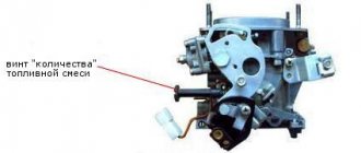
SeAZ Oka Okula › Logbook › Adjusting the ignition and carburetor
There is no need to demand any intelligible traction from the Okula, this is not what this kart was created for, but nevermind, before the visit to the carburetor engineers, it was completely choking on gasoline, the idle speed was high, the ignition was late. Consumption was about 8 liters in the city and 6 on the highway.
I came to the service center, they removed the carb, blew it out/washed it, everything was displayed at face value on a special stand. After several years of inactivity, the carb was completely clogged.
Initially, on the gas analyzer at idle, the exhaust contained more than 6 units. CO, and adding gas, the value increased. After tuning at idle, CO was 3 units. and about 1 unit. when adding gas.
We set the ignition on the strobe light, it was late.
Now the engine is almost inaudible, the idle speed is smooth, and the dips in traction when adding speed have disappeared. I’ll go again in 3-4 days to check)