Parts of the engine gas distribution mechanism experience heavy loads and high temperatures during operation. When heated, they expand unevenly, as they are made of different alloys. To ensure normal operation of the valves, the design must provide a special thermal gap between them and the camshaft cams, which closes during engine operation.
The clearance must always remain within the specified limits, so the valves require periodic adjustment, that is, selecting pushers or washers of the required size. Hydraulic compensators, sometimes called simply “hydriki” or hydraulic pushers, can eliminate the need to adjust the thermal gap and reduce noise on a cold engine.
Design and principle of operation of hydraulic compensators
| The dimensions of the parts of a running internal combustion engine increase due to heating. To prevent this from leading to breakdowns, accelerated wear, and deterioration in the performance of power units, thermal gaps are created between some parts at the design stage. When the engine warms up, due to the expansion of the parts, they are “selected” (absorbed). However, as parts wear out, their heating is not enough to absorb the gaps, which negatively affects engine performance. The thermal gap in the valve drive mechanism directly affects the performance of the power unit. Since valve clearances are constantly changing due to wear of parts, at the beginning of the last century a mechanism for adjusting them was introduced into the engine using ordinary wrenches. This had to be done regularly, which means that the labor intensity of maintenance increased and its cost increased. Hydraulic compensators (HC) allow you to avoid these problems. They must completely absorb the gaps between the working surfaces of the camshaft and the rockers, rocker arms, valves, rods - regardless of the temperature conditions and the degree of wear of the parts. |
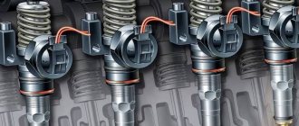
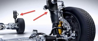
Hydraulic compensators can be installed on all types of gas distribution mechanisms (GRM) - with rocker arms, levers, rods - and with any camshaft location (upper or lower, Fig. 1).
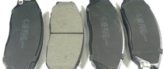
Depending on the design of the timing belt, there are four basic types of hydraulic compensators (see photo below): hydraulic pushers; hydraulic supports; hydraulic supports designed for installation in levers or rocker arms; roller hydraulic pushers.
Historical excursion
Hydraulic compensators, also known as hydraulic pushers, or in common parlance “hydriki”, appeared quite a long time ago. Let's look at why compensators are needed and how they appeared in the engines of many cars.
Drivers largely owe their appearance in the design of gas distribution mechanisms of cars to Japanese auto engineers, since it was they who began to massively use “hydraulic valves” in the design of engine timing systems. At that time, when designing an internal combustion engine, much attention was paid not only to its main components (crankshaft, pistons, connecting rods), but also to the details of the gas distribution mechanism. Engineers gradually “brought” previous generations of their power units to perfection. Thus, hydraulic pushers replaced the usual mechanical pushers.
Design of hydraulic compensators
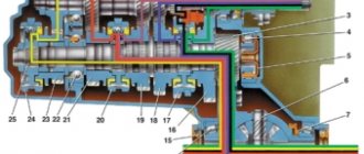
Let's look at the design and principle of operation of a hydraulic compensator using the example of a hydraulic pusher installed in the cylinder head. The remaining types of hydraulic compensators, although different in design, work on the same principle. The hydraulic pusher is a housing, inside of which a movable plunger pair with a ball valve is installed. The body is movable relative to the guide seat made in the cylinder head. If the hydraulic valve is mounted in valve drive levers (in rockers or rocker arms), its moving part is only a plunger, the protruding part of which is made in the form of a ball joint or support shoe.
The main part of the main body is a plunger pair. The gap between the sleeve and the plunger is only 5-8 microns, which ensures a high tightness of the connection, while maintaining the mobility of the parts. There is a hole at the bottom of the plunger for oil to enter, which is closed by a spring-loaded check ball valve. A fairly stiff return spring is installed between the sleeve and the plunger.
Operating principle of hydraulic compensators
When the camshaft cam is positioned with its back to the tappet housing (Fig. 2a), there is no external compressive load and there is a gap (H) between the housing and the cold engine cam. The return spring pushes the plunger until this gap is “selected” - reduced to almost zero. At the same time, oil from the engine lubrication system through the ball valve and the bypass channel enters the internal cavity of the plunger and fills it.
As the shaft turns, the cam begins to put pressure on the pusher body and moves it down, blocking the oil channels - the engine lubrication system and the bypass channel (Fig. 2b). The ball valve closes and the oil pressure under the plunger increases. Since the fluid is incompressible, the plunger pair begins to act as a rigid support, transmitting the force of the cam to the engine valve stem.
Although the gap in the plunger pair is very small, a little oil is still forced back through the technological gap between the plunger and the bushing, so the pusher lowers (“sags”) by 10-50 microns. The amount of “drawdown” depends on the engine crankshaft speed. If they increase, by reducing the time of pressing on the hydraulic pusher body, oil leaks from under the plunger are reduced.
The formation of a gap when the cam leaves the pusher is eliminated due to the action of the plunger return spring and the oil pressure in the engine lubrication system. Thus, the hydraulic compensator ensures the absence of gaps - due to a constant rigid connection between the timing elements. Due to engine heating, the length of the parts of the hydraulic compensator itself changes slightly, but it automatically compensates for these changes.
"Pros" and "cons" of using hydraulic compensators in engines
The introduction of the hydraulic valve made it possible to avoid adjusting the clearances of the valve mechanism and make its operation “softer”; reduce shock loads, that is, reduce wear on timing parts and eliminate increased engine noise; more accurately observe the duration of the valve timing, which has a positive effect on the safety of the engine, its power and fuel consumption.
With all their advantages, hydraulic compensators also have disadvantages, and engines equipped with them have some operating features. One of the design flaws of simple hydraulic compensators manifests itself in poor performance of a cold engine in the first seconds of start-up, when there is no oil pressure in the lubrication system or it is minimal. Read about the features of operation, repair and maintenance of engines with main thrusters in the following issues of AC.
| There are no consequences |
Intake and exhaust valves heat up to different temperatures, so the thermal clearances required for them are different: for intake valves - 0.15: 0.25 mm, and for exhaust valves - 0.20: 0.35 mm and even more. If these values are not met, the consequences can be very different:
|
| Historical reference |
| The first patents for hydraulic valve lash compensators were registered in the USA in 1920. Since 1960, 90% of all American passenger cars have been mass-produced with hydraulic lifters. Production of HA in Germany began in 1971. Since 1978, most other leading automobile companies have been using this technology as standard. |
A little history
Hydraulic compensators have replaced less efficient mechanical regulators of gas distribution mechanisms. As a rule, a regular engine valve, say on a classic VAZ 2105 - 2107 engine, does not have a hydraulic compensator, so it often had to be adjusted, on average after 10,000 kilometers. Valve adjustment on VAZ 2105 - 2107 was done manually, that is, you had to remove the valve cover and set the gaps using a special feeler gauge, which varied in thickness, which means you could choose it for your mileage.
If adjustments are not made, the car engine begins to make noise, dynamic characteristics decrease, and fuel consumption increases. I made a detailed video on why you need to adjust the valves, watch it useful.
After 40 - 50,000 kilometers, the valves generally should have been changed. That is, mechanical valve adjustment, to put it mildly, has outlived its usefulness, it was necessary to do something, to improve the design, so to speak.
So on front-wheel drive VAZ engines, they began to install mechanical pushers in front of the valve. To exaggerate, a large “cap” was simply put on top of the valve; it has a larger diameter (than the old design), and therefore wear was much reduced, because it is much more difficult to wear out a larger diameter than a small one. But adjustment still remains, of course not every 10,000 kilometers, much less often, but it is still recommended to do it. This usually happened by placing repair “washers” of increased height. Mechanical adjustments are quite effective and are still used by some manufacturers; adjustment with washers is recommended no earlier than 40 - 50,000 kilometers (if we talk about our VAZs); on some foreign cars the pushers last even longer. The big advantages are the simplicity of the design, unpretentiousness (semi-synthetic oils can be poured), as well as the relative cheapness of the design. The disadvantages can be noted that when the “washers” on top were worn out, the engine began to work noisier, the dynamic characteristics dropped and the consumption increased. What was needed was a design that automatically adjusted the gap.
And now, mechanical valve adjustment has been replaced by a completely new technology. Everything is simple here - now you don’t need to adjust the valves manually, hydraulic compensators will do everything for you. They themselves will set the required engine valve clearance, due to which the engine life is increased, power is increased, fuel consumption is reduced, and the mechanism runs for quite a long time - 120 - 150,000 kilometers (with proper maintenance). In general, a step forward.
The other side... supports
The main reasons for the failure of the hydraulic compensator (HC) are contamination of the engine oil channels and wear of the working surfaces of the check valve and plunger pair, manufactured with a high degree of precision. Contamination is caused by the use of inappropriate oil, failure to comply with oil change intervals, or a malfunction of the oil filter that allows dirty oil to pass through the bypass valve.
As the seating gap in the plunger pair increases, oil leakage from the high-pressure chamber increases. The hydraulic compensator loses its “stiffness”, so the efficiency of transmitting the force of the cam to the timing valve stem decreases. The same thing happens when the check valve of the high-pressure chamber wears out. Malfunctions in the engine lubrication system slow down the filling of the main gearbox with oil and do not allow gaps in the timing belt to be absorbed.
The internal volume of the HA must be filled with oil. An empty or partially filled ("aired") hydraulic compensator does not fulfill its main purpose - eliminating gaps in timing parts. As a result, shock loads occur, which manifest themselves as a characteristic knock. This leads to accelerated wear of timing parts and deterioration of engine performance. Breakdowns can also be caused by particles of worn parts getting into the hydraulic fluid with oil: the unit can jam. Depending on the position in which this happened, large gaps will either appear in the timing belt, or the valves will be “pinched” (the load on the camshaft increases, power decreases, etc.).
To avoid this, you must:
- control and maintain the internal cleanliness of the engine - change the oil and oil filter within the time limits recommended by the car manufacturer, with a reduction factor of 0.6 - 0.9, taking into account the operating conditions of the vehicle;
- Flush the engine before the next oil change, using slow-acting “mileage” flushes. If the internal surfaces of the engine are contaminated (which is discovered, for example, when removing the timing case), it is not recommended to use quick-acting flushing agents, since exfoliated pieces of dirt with the flow of oil can get into the internal cavities of the compensators and damage them.
You need to know that small gaps between the moving elements of the hydraulic compensator determine the use of high-quality low-viscosity oils in the engine - synthetic or semi-synthetic (SAE 0W40, 5W40, 10W30, etc.). It is not recommended to use mineral oils (for example, SAE 15W40) due to their high viscosity and tendency to form tar deposits.
Diagnostics and replacement of hydraulic compensators
When one or more main valves fail, a knock similar to a valve valve appears. This sound travels well in metal, so a phonendoscope is used to determine a faulty hydraulic compensator. An analogue of this device can be made independently from a steel rod about 700 mm long and 5-6 mm in diameter. A beer can with the top cut off is attached to one end of the rod, and a wooden handle is attached to its middle. By placing your ear to the can and alternately placing the free end of the “phonendoscope” against the head of the block in the area of each compensator, the faulty one is determined by ear by the increased knocking. The “suspicious” HA should be dismantled and checked.
You can remove the main body from the seat using a magnet. If this fails (the main body is “stuck” or jammed), it is removed with a puller, having first welded a rod with a hook to it. Some hydraulic compensators can be disassembled, which allows you to determine the degree of wear of internal parts. Disassembly should be done with extreme care so as not to damage the surfaces of the mating elements.
The hydraulic supports are disassembled after removing the retaining ring; the internal parts of the hydraulic pusher are “shaken out” by gently tapping its body on a metal surface. The contaminated compensator is washed in acetone or another solvent.
Visual inspection allows you to detect external damage to the end surface of the hydraulic compensator exposed to loads (potholes, scratches or scuffs). During operation, a depression may even form on it.
There is another simple and effective way to monitor the condition of a dismantled main body: after filling with oil, it should not shrink when hand force is applied. Otherwise, it is faulty and must be replaced. An efficient main body, compressed in a clamp, exhibits significant resistance and slightly reduces the length only after 20-30 seconds.
Secrets of installing hydraulic compensators
For the normal functioning of the timing belt with hydraulic compensators (after replacing them), certain rules must be followed:
- New HAs are filled at the factory with a preservative oil composition, which does not need to be removed during installation. After starting the engine, this composition is mixed with oil from the engine lubrication system without any consequences;
- You should not install empty hydraulic compensators in the timing belt, the “airiness” of which was formed as a result of disassembly and washing. First they need to be filled with oil. Failure to comply with this rule can lead to significant shock loads, especially when starting the engine for the first time (while the lubrication system is being pumped);
- After installing the main gear on the engine, it is recommended to turn the crankshaft using the ratchet 5-7 times with a key and wait 10-15 minutes before starting the engine for the first time. This is necessary so that, under the pressure of the camshaft cams, the plunger pairs of loaded compensators take their working position;
- When repairing and replacing the engine, you need to flush the oil system, replace the oil filter, and fill the engine with fresh oil. By rotating the crankshaft, you can visually check the flow of oil through the oil channels to the installation seats (with the hydraulic compensators removed);
- When repairing the engine of a car with a mileage of over 150-200 thousand km, it is advisable to replace the hydraulic valve clearance compensators (with such mileage, as a rule, they fail). The use of low-quality oils and failure to comply with the timing of their replacement can halve the service life of the hydraulic system;
- if there are one or more faulty hydraulic compensators, it is advisable to change the entire set, otherwise you will soon have to re-open the timing belt for repairs.
Hydraulic compensator for a car - simple about complex things!
In order to understand the principle of operation of the hydraulic compensator, and therefore determine why it fails and how to repair it, you need to remember the design of the engine. Do you remember how the valves are located and what they are for? The intake valve is responsible for the supply of fuel, and the exhaust valve is responsible for the exit of gases exhausted during fuel combustion in the engine.
So, a hydraulic compensator is a device that regulates the valve clearance automatically, thus ensuring a uniform supply of fuel to the working chamber of the engine and the exhaust outlet. Installing hydraulic compensators eliminates the process of manually adjusting the valves for the manufacturer's servicemen, which, by the way, is very labor-intensive and time-consuming.
Bleeding hydraulic compensators
Under certain operating conditions of the vehicle (long breaks in operation, wear of the hydraulic valve plunger pairs), partial leakage of oil from the hydraulic compensators (airing) may occur. This is manifested by knocking noises in the timing drive of a warm engine.
You can remove air from the compensators as follows: first let the engine run for 2-3 minutes. at constant speeds (2-2.5 thousand rpm), then at variable speeds (2-3 thousand rpm), and after that 30-50 seconds at idle. The noise in the timing belt should disappear, but if it persists, the entire cycle is repeated, sometimes several times. If this does not help, you should look for faulty main valves and the reason for their failure.
Prices
Replacing compensators is not a cheap pleasure. The cost of one new civil code, depending on its type, is 27-109 UAH. The work of replacing a set of hydraulic compensators at a service station will cost the owner another 150-170 UAH. If the valves “knock” (due to wear of the plunger pair), you can temporarily postpone the repair by replacing the engine oil with a more viscous one. It is possible to replace synthetic oil with semi-synthetic oil, and in used foreign cars - even with mineral oil. Although in the latter case, as we previously mentioned, other negative phenomena may appear.
Debugg
Since there are several hydraulic compensators in a car, it is worth using acoustic diagnostics to determine the faulty one, i.e. to the sound. After detecting a faulty one, it must be washed, returned to its place and the engine restarted. But if this does not help, then it needs to be replaced.
How to wash the hydraulic compensator?
The mechanism in question must be washed in a room protected from dust and drafts.
Prepare three containers for the size of the compensator and a flushing liquid, for example, kerosene or 92-octane gasoline.
Before washing, leave the car in the garage for a day to allow as much oil as possible to drain into the pan.
Further actions are as follows:
- Disconnect the battery to de-energize the car.
- Get rid of the air filter.
- Remove the bolts to remove the cylinder head cover.
- Remove the hydraulic compensator from its sockets after removing the rocker arm axles.
- Use a synthetic bristle brush to clean the outside of parts.
- Wash the hydraulic compensators in the first container. To do this, immerse each of them in the liquid and press the ball valve through the hole in the plunger using a wire. Be careful not to break the spring. Next, press the plunger itself. As soon as you notice that the movement has become easier, carefully squeeze out the valve ball and drain the fluid from the compensator. Use a syringe to additionally rinse the channels in the body and proceed to a similar rinse in the second container.
- At the final stage, you will be tested; for this you will need a third container with flushing liquid. How to check hydraulic compensators before installing them in place? It is enough to dip them into the third container, draw liquid into the HA and lower the valve, then remove the part with the plunger up. If you press the plunger with your finger, it should not move.
- If there is no movement, return the parts to their place by installing the rocker arms, cylinder head cover and other elements. Remember to tighten the bolts from the middle to the edges.
After the assembly is completed, start the engine and wait a couple of minutes until it idles, at which there should be no knocking after flushing. Cleaning also helps get rid of knocking after the engine warms up and reaches operating temperature.
Replacing the hydraulic compensator
- Remove the faulty mechanism using a puller or magnet. The latter method is advisable only when the hydraulic compensator moves freely. If it is stuck to the outer surface, only a puller will help.
- Wash the entire oil supply system, replace the oil filter and fill in new oil, check its supply to the seat of the compensators by turning the crankshaft. The hydraulic compensator should already be removed.
- It is strictly prohibited to install expansion joints without oil, otherwise critical shock loads will occur.
- After installing the new mechanism in its seat, do not start the power unit immediately. Use the wrench to turn the crankshaft a few turns and wait half an hour. During this time, the parts will find their jobs, and the internal pressure will normalize.