The Torsen differential is a type of limited-slip limited-slip worm differential. Like any other differential, it is designed to distribute torque between the drive wheels or between the drive axles. The name of the mechanism comes from the phrase Torque Sensing, which translates as “torque sensitive”. Let's consider the operating principle, main components, as well as the pros and cons of this transmission device of different generations.
Advantages and disadvantages
Let's start with the advantages of the Torsen differential:
- high precision work
- smooth operation
- low noise level during operation
- The distribution of vehicle engine power between the wheels or drive axles occurs automatically and does not require driver participation
- instant redistribution of torque does not affect the braking process
- with correct operation, practically no maintenance is required (only monitoring the transmission oil level and its timely replacement are necessary)
Disadvantages of the Thorsen differential:
- high cost due to the complexity of manufacturing and assembling the mechanism
- increased fuel consumption due to friction losses of mechanical device elements
- relatively low efficiency
- predisposition to jamming
- high wear of loaded elements
- the mechanism requires special lubricants due to significant heat generation during operation
- accelerated wear of parts when using wheels of the same axle with different characteristics (for example, when installing a spare wheel that differs from the installed wheels)
Device
Design and principle of operation of the multitronic gearbox
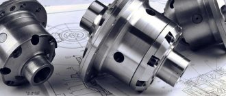
This mechanism is made of familiar elements - the device is similar to any planetary unit. You can highlight the main parts - this is the body, worm gears, satellites.
As for the general concept, there are not many differences here when compared with ordinary mechanisms. The housing is rigidly mounted on the drive unit of the transmission. Satellites are installed inside the case. They are fixed on special axes. The satellites are in rigid engagement with the axle gears. The gears of the axle shafts are mounted on shafts, to which torque is transmitted.
And now regarding the Thorsen mechanism itself. In this unit, the axle gear has helical teeth. This is nothing more than a traditional worm shaft.
The satellites are a pair of helical gears. One element of this pair forms a worm pair with the axle gear. A pair of satellite gears can also interact with each other due to spur gearing. The design has as many as three satellites, each of which represents a pair of gears.
Main components of a node
Torsen consists of the same components as any planetary node and includes:
- body (cup);
- worm gears;
- satellites.
Torsen T2 layout
The overall concept of the Torsen is also no different from a conventional differential. The housing of the unit is rigidly fixed to the drive element of the transmission. Inside this cup there are satellites mounted on the axles and having gearing with semi-axial gears mounted on the shafts to which rotation is transmitted.
Now about the features of Torsen . The teeth of the semi-axial gear are helical, that is, this element acts as a worm (drive element of the transmission).
Torsen satellites are presented in the form of pairs of helical gears. One element of such a pair forms a worm pair with its drive gear (semi-axial). In this case, a pair of satellite gears also interacts with each other through spur gearing. In total, the differential design uses three satellites, each of which consists of two gears.
Torsen T1 device
Purpose
What is 4wd all-wheel drive and how does it work? principle of operation and why it is needed
So, what is this mechanism for? The simplest differential is capable of distributing power or torque between two wheels equally, evenly. If one wheel slips and cannot grip the road surface, then the torque on the second wheel will be zero. Improved models, and the vast majority of them are differentials with a self-locking mechanism, are equipped with a system that blocks the suspended axle shaft. Then the torque is distributed so that the maximum power is on the wheel that maintains good grip.
The Thorsen differential is the most optimal solution for an all-wheel drive vehicle, which is operated mostly in difficult conditions. “Thorsen” is not the name of the developer, but an abbreviation. This stands for Torque Sensing.
Application
Design and principle of operation of a manual gearbox
Torsen self-locking differentials are used both as inter-wheel and inter-axle torque distribution devices. The Torsen Audi Quattro differential is widely known. In modern all-wheel drive vehicles, this mechanical device is installed quite often. Note that the Torsen center differential is used on almost all Hummer cars.
The popularity of the Thorsen torque vectoring device is due to the lack of communication with any electronics or clutches. This transmission element is a relatively simple mechanism, characterized by instantaneous operation and the absence of a negative impact on the braking process. That is why leading automakers use this type of differential in their cars.
DPS
Dual Pump System - a system with two pumps that automatically connects the second axle when one is not enough. Used in Honda all-wheel drive systems. Advantages: works automatically, saves gasoline on good roads. Disadvantages: limited cross-country ability, complexity, towing restrictions.
Gear self-locking differentials
There are three types of such differentials:
- planetary
- Quaife
- Torsen.
All of them are based on the property of a helical or worm gear to “jam” at a certain torque ratio. Such differentials transfer most of the torque (up to 80%) to the non-slip wheel. Used in SUVs and racing cars. Disadvantages: complexity; greater power loss than a conventional differential. The Torsen type differential was invented in 1958 by the American Vernon Glizman. It has the advantages of a viscous coupling and does not have its disadvantages. The operating principle is based on the “wedging” property of the worm gear. The name Torsen comes from the English. Torque sensitive. Torsen is a trademark of JTEKT Torsen North America Inc.
There are not so many types of designs - three main ones can be distinguished:
First type (T-1).
The worm pairs are the drive axle gears and satellites.
In this case, each axle axis has its own satellites, which are connected in pairs with the satellites of the opposite axle axis by a conventional spur gear. It should be noted that the satellite axis is perpendicular to the semi-axis. With normal movement and equality of moments transmitted to the axle shaft, the worm pairs “satellite / drive gear” are either stopped or rotated, providing a difference in the angular speeds of the axle shafts when turning. As soon as the differential tries to transfer torque to one of the axle shafts, the worm pair of this axle shaft begins to wedge and block with the differential cup, which leads to partial blocking of the differential. This design operates in the widest range of torque ratios - from 2.5/1 to 5.0/1, that is, it is the most powerful in the series. The operating range is adjusted by the angle of the worm teeth. Fig.10 Fig.11 Second type (T-2).
The author of this type is the Englishman Rod Quaife. In this case, the axes of the satellites are parallel to the semi-axes.
The satellites are located in peculiar pockets of the differential cup. In this case, the paired satellites have a helical gearing, which, when wedged, also participates in the blocking process. EATON's TrueTrac differential has a similar device. Even here in Russia, the production of similar differentials has appeared for domestic UAZ cars, etc. Fig. 12 Fig. 13 The third type (T-3).
The planetary structure of the structure allows the nominal torque distribution to be shifted in favor of one of the axes. Partial locking occurs when there is a 20–30% difference in the torques transmitted to the axis. This differential structure makes it compact, which in turn simplifies the design and improves the layout of the transfer case. Fig. 14 Unlike other designs, torque sensors work in almost any conditions. Even if the wheels rotate at different speeds (turning, going over bumps), they still always receive torque based on traction. Fig. 15 In general, a shift in the nominal torque distribution between the axles is possible in the range from 65/35 to 35/65. Partial locking occurs when there is a 20–30% difference in the torques transmitted to the axis. Also, such a structure of the differential makes it compact, which in turn simplifies the design and improves the layout of the transfer case. The torque sensitive differentials described above are very popular in motorsport. Moreover, many manufacturers install such differentials on their models as standard, both as center and cross-axle differentials. For example, Toyota installs such differentials both on passenger cars (Supra, Celica, Rav4, Lexus IS300, RX300, etc.) and SUVs (4Runner / Hilux Surf, Land-Cruiser, Mega-Cruiser, Lexus GX470) and buses (Coaster Mini-Bus). These differentials do not require the use of special oil additives (unlike friction-based differentials), however, it is better to use high-quality oil for loaded hypoid gears. Not lower than API GL-5.
Kinds
Designers have developed three types of Torsen differentials , which are designated by the letter index “T” with a digital prefix. The differences between them come down to the layout of the unit and the shape of the working elements, which in turn affects the performance indicators.
Types of Torsen designs
The first type is Torsen T1. Its distinctive features are the arrangement of satellite pairs perpendicular to the axle axes and the use of helical teeth on both axle gears and satellites. The satellites of the pair interact with each other using spur gearing. The operating principle described above is discussed using the T1 version as an example. Has a high degree of “natural” friction.
Torsen T2 is the second generation of this limited-slip differential. It differs from the first type by the parallel arrangement of the satellites. It has helical teeth only on the satellites, but the semi-axial gears are helical. The engagement of the satellites with each other is also carried out by screw teeth, which participate in the blocking process (they can also wedge).
This generation has a lower degree of "natural" friction, early setting with less locking compared to T1. It has become widespread on civilian cars. But there is a modification called T2R, which can withstand high torque and is used exclusively on powerful cars such as the Ford Mustang. In design, it differs only in that it uses a splined coupling with helical teeth, through which it engages with the sun gear. In such a design, the characteristics of “natural” friction can change depending on driving conditions.
The last type is T3. Structurally, it is in many ways similar to the T2 version (parallel arrangement of satellites with helical teeth, helical semi-axial gears), but its layout was somewhat revised and a planetary structure was used in its design. This made it possible not only to reduce the overall parameters of the unit, but also to provide the ability to set the torque distribution ratio along the axes. Because of this feature, Torsen T3 is used only as a center differential, while T1 and T2 are used both between axles and as a cross-axle differential.
Device and main components
Audi Quattro
Let's look at what basic elements Thorsen consists of:
- Housing (other name: “differential cup”). It transmits torque from the main gear to the side gears through the satellites. The driven gear of the main gear is mounted on it. Inside the differential cup there are axles on which the satellites are mounted.
- Right and left side gears (other name: “sun gears”). They transmit torque to the axles/half shafts through a spline connection.
- Satellites of the right and left semi-axial gears. The differential cup and side gears are connected. Thorsen has four satellites in its design.
- Output shafts.
Note that this type of self-locking differential has the most advanced design.
Types of limited slip differentials
To eliminate the above shortcomings, a differential was introduced into the vehicle’s transmission, which should also transfer all loads received from the engine to the wheels. On cars of earlier releases, planetary differentials of a classical design with a symmetrical torque distribution scheme were installed.
This differential only partially eliminated these shortcomings. Since the 30s of the last century, research has been carried out on the use of limited slip differentials. They were installed first on sports cars, and then in production SUVs and road cars. The most widely used limited slip differentials are: FRICTIONAL
• self-locking friction multi-disc differential.
Consists of a housing, satellites, satellite axle, output axle shafts, axle shaft gears, disk packages. The discs are alternately connected to the differential housing and the axle gears. The discs are spring loaded. The work is based on the synchronous rotation of the axle shafts with the body on a straight section of the road and the difference in rotation when performing maneuvers. In this case, the clutch comes into operation and supplies additional torque to the lagging gear. Having in their design spring-loaded friction disc packs. They have a static pretension (actuation moment) from 2 to 12 kg/m. Used in motorsports, they wear out quickly and require intervention to restore performance after each race. • self-locking gerotor differential. The design is similar to the differential described above, only instead of springs a pressure piston and a hydraulic pump are installed. The friction discs are compressed by a piston under fluid pressure from one or two gear pumps. The disadvantages are approximately the same as for a spring-loaded clutch • cam (gear) differential. Consists of a separator, an outer sprocket, an inner sprocket, crackers, two axle shafts, a driven gear of the main gear, and a housing. Based on the use of cam (gear) pairs instead of a planetary mechanism. With a small difference in the angular velocities of the axle shafts, the gear pairs rotate mutually, and when they slip, the axles are blocked. Positive aspects: simplicity of design, easy installation, low cost. Negative aspects: harsh operation, low efficiency, increased fuel consumption. In this regard, they are installed mainly on military and special equipment. • viscous coupling. It consists of a housing, a drive shaft, a driven shaft, a package of disks (drive and driven shaft disks), a hub, a pressure plate, 2 annular injection pistons, an annular working piston, and a balancing spring. The operating principle is based on filling the inter-disc space of the clutch with a dinatant liquid, silicone, capable of thickening and increasing in volume as the temperature rises. As the difference in the rotation of the axle shafts increases, the temperature from friction increases, and accordingly, the viscosity of the fluid increases and, as a result, the adhesion of the discs. Advantages: simplicity of design and operation. Disadvantages: low efficiency, cumbersome design, inertness in use. Due to their massiveness, they are mainly used for center differentials. GEAR
• self-locking differential (QUIF). Consists of a housing, satellites of the left and right rows, semi-axial gears (left and right), 2 output shafts. In this differential, the axles with satellites are closed in the housing (in special holes), located in two rows parallel to the axis of rotation of the housing. Satellites from different rows engage each other in pairs with helical teeth. • “torsen” of the first type. Consists of a housing, satellites of the left and right rows, right and left axle gears, 2 output shafts. "Torsen" of the first type. Each axle axis has its own satellites, connected in pairs with the satellites of the other axle axis. The gearing is spur-toothed, the satellite axis is perpendicular to the axle axis.
• “torsen” of the second type. Consists of a housing, a satellite connected to the right axle gear, a satellite connected to the left axle gear, right and left side gears, left and right output shafts. "Torsen" of the second type. Helical gears of axle shafts and screw satellites are used. The axes of the satellites are parallel to the semi-axes.
Hard lock
The main feature of the rigid type of locking is that, once engaged, it distributes the torque equally between the axles. That is, the drive axle begins to work as if there was no differential in its design at all.
The simplest design of a complete lock is to create a rigid connection between the differential housing mounted on the driven gear of the main gear and one of the axle shafts. As a result of this connection, the differential loses the ability to distribute rotation and transmit it to only one wheel.
The simplest design of a complete lock is reduced to fitting an additional clutch with a control mechanism onto the splines of the axle shaft. This clutch, as well as the differential housing, has teeth that engage these elements.
To lock, you just need to engage the clutch with the body and the axle shaft becomes rigidly connected to the main gear.
Mechanical interlock
Full locking is used on both cross-wheel and center differentials of SUVs and has exclusively forced manual engagement. At the same time, this mechanism is often not used on the front axle so as not to affect the car’s handling.
The operating principle of the full locking mechanisms is identical for all options; the differences are only in the design. But their drives can be different:
- mechanical;
- hydraulic;
- pneumatic;
- electric.
In this case, all types of drives perform one task - they engage the coupling with the housing.
The mechanical type of drive is presented in the form of a system of rods and levers, the hydraulic one is represented by two cylinders (main and working) connected to each other by a pipeline, the pneumatic type is represented by a pneumatic cylinder with a working chamber, and the electric one is by an electric motor.
The advantage of hard locking is to ensure high cross-country ability of the car, since under any conditions the wheels always move at the same speed.
But there are also disadvantages:
- Increased load on the transmission;
- Inability to drive on paved roads;
- High speeds of movement are not allowed;
- Manual control.
Despite this, many fans of full-fledged SUVs prefer this type of locking.
Pros and cons of a Torsen differential
increased consumption of lubricants Torsen differentials correct operation reliable operation of the worm pair with different characteristics
Hypoid pairs are the gears of the drive axles and satellites. In this case, each axle axis has its own satellites, which are connected in pairs with the satellites of the opposite axle axis by an ordinary spur gear (in this case, the axis of the satellite is perpendicular to the axle axis). During normal movement and equality of torques transmitted to the axle shafts, the hypoid pairs “satellite / drive gear” are either stopped or rotated, providing a difference in the angular speeds of the axle shafts when turning.
As soon as one of the axle shafts begins to slip and the torque on it drops, the hypoid axle/satellite pairs begin to rotate and wedge, creating friction with the differential cup and with each other, which leads to partial locking of the differential. Due to the friction moment, the differential redistributes torque in favor of the lagging axle shaft.
This design operates in the widest range of torque distribution - from 2.5/1 to 5.0/1. The operating range is structurally regulated by the angle of inclination of the worm teeth.
T-2, Type B
To uncover…
This type of differential was invented by the Englishman Rod Quaife. It uses helical gears of the axle shafts and helical gears of the satellites (the axes of the satellites are parallel to the axle shafts). The satellites are located in peculiar pockets of the differential cup, while the paired satellites form another screw pair between themselves, which, when wedged, also participates in the locking process. The T-2 differential uses a slightly different arrangement of the same device. In it, paired satellites are connected to each other on the outside by sun gears. Compared to the first type, these differentials have a lower locking ratio, but they are more sensitive to torque drop and operate earlier (starting from 1.4/1).
In particular, True Trac and Electrac differentials (the latter is equipped with forced electric locking) from Tractech have such a device. Russia also produces similar differentials for domestic cars.
T-3, Type C
To uncover…
The third type is used mainly for center differentials. As in the second type, this differential uses helical axle gears and helical pinion gears. The axes of the satellites are parallel to the semi-axes. The planetary structure of the design allows the nominal torque distribution to be shifted in favor of one of the axles (for example, 4Runner 4th generation: 40/60 in favor of the rear axle). Accordingly, the entire range of partial blocking is shifted: from 53/47 to 29/71. In general, the nominal torque distribution between the axles can be shifted in the range from 65/35 to 35/65. Partial blocking occurs already at 20-30% of the torque difference. This structure of the differential makes it compact, which, in turn, simplifies the design and improves the layout of the transfer case.
Three operating modes
If we consider the full operating principle of the Thorsen differential, we must say that the system can operate in three different modes. The specific mode depends on the level of resistance on the wheel. When it is the same, the torque is distributed evenly.
If the resistance on one of the wheels increases, then the worm pair is switched on, and thus the second pair is activated, despite the slight resistance on it. This leads to the redistribution of torque as needed. In this case, one wheel will slow down. The second one will spin faster.
If one of the tires completely loses resistance, then this will be accompanied by blocking or jamming of the worm pair due to high friction. Then the second pair immediately slows down. The torque is leveled out. The operation of the Thorsen differential in this mode is similar to straight-line movement.
Operating principle
Let's look at the essence of Torsen's work using an example where the unit is inter-wheel. When moving in a straight line, the drive wheels encounter the same resistance, so the unit evenly redistributes the torque between the wheels. During this movement, the satellites do not rotate and directly transfer force from the cup to the semi-axial gears (hard transmission).
When entering a turn, the wheel running along the inner radius encounters more resistance and slows down. As a result, the worm pair of this wheel is put into action - the semi-axial gear begins to rotate its satellite gear. That, in turn, transmits force to the second satellite gear, which additionally turns its side gear, increasing the torque on the wheel moving along the outer radius. Since the difference in moments on the axes is small, the friction force in the second worm pair is low and self-braking does not occur.
When one of the wheels hits a slippery surface, the resistance on it drops and the torque tends to this wheel. The side gear begins to spin its satellite gear, which then transmits force to the second satellite, and this is where the self-braking effect occurs. The satellite gear cannot act as a driving element and rotate the semi-axial gear due to the nature of the worm gear. Therefore, this worm pair jams. When jammed, it slows down the rotation of the second worm pair and the moment on the axle shafts is equalized.
The principle of operation of the differential between the axles
If we consider the whole principle of operation briefly, then Torsen can operate in three modes, depending on the resistance on the wheels. With the same resistance, the differential distributes torque evenly (the worm pairs are immobilized, and the differential appears to be locked).
When the resistance on one wheel increases, its worm pair is activated and forces the second to rotate, despite the appearance of a small resistance force in it, which leads to a redistribution of the moment in the desired ratio (one wheel slows down, and the second rotates faster).
The loss of resistance on one of the wheels is accompanied by jamming of the worm pair (due to high friction forces), which immediately slows down the second pair, so the torque on both wheels is equalized. In this case, Torsen begins to work in the same mode as during straight-line movement.
Classic: Quattro with self-locking Torsen.
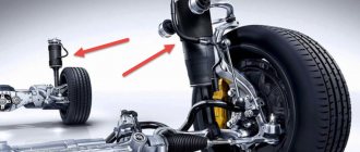
Quattro permanent all-wheel drive with self-locking center differential.
This type of all-wheel drive has been in use since 1988. It is based on a Torsen self-locking differential. Of course, over 30 years the differential itself has undergone changes, which mainly concern torque distribution. If the differential was originally symmetrical, then in the newest Audi models it distributes torque between the axles in unequal proportions. Today, a self-locking center differential provides asymmetrical dynamic torque distribution of up to 70% to the front axle or up to 80% to the rear. Torque redistribution occurs without any
delay and does not require regulatory intervention of the ESC system. Quattro all-wheel drive with a Torsen self-locking center differential can now be found on the largest Audis. For example, on the new Q7. For an additional fee, it can be “crossed” with a sports rear differential. But the second generation Audi Q5 has already switched to a drive called Quattro Ultra.
Installing a limited slip differential.
Differentials are installed on all types of cars. On machines with one drive axle, one differential is installed on the drive axle, between the wheels. On cars with a connected second drive axle, two differentials are installed, one on the axle, and also between the wheels. On vehicles with permanent all-wheel drive, three differentials are installed: one center differential, and one each on the axles between the wheels. The inter-wheel differential distributes the load between the wheels, depending on their operating conditions, and the inter-axle differential distributes the load between the axles. All types of differentials under consideration can be installed between the axles of all-wheel drive vehicles, as well as between the axle axles (interwheel) of all-wheel drive vehicles and those with a single axle drive. The viscous coupling, due to its massiveness, is installed mainly between the axles. To install a differential, it is necessary to thoroughly examine the design features of the machine’s transmission and determine what type of differential is suitable for installation (despite the universality of differential manufacturing, there are differences that do not allow installation without modifications, replacement of parts or units). The installation of limited slip differentials must be performed by highly qualified specialists. If it is necessary to carry out modifications, there may be a need for turning, milling, grinding and other machines.
Principle of operation
General view of the Torsen differential
Thorsen is a worm-type limited slip differential. This means that automatic differential locking occurs when there is a difference in torque on the body of the mechanical device and on the drive shaft. The differential itself consists of driven and driven worm gears, which are called “semi-axial” and “satellites”, respectively. The worm gear has one feature: it does not rotate from other gears, but it can itself rotate other gears. This property (wedging) allows the differential to be partially blocked.
Let's look at how the center worm differential works.
If the wheels of a car have good grip on the road surface and move smoothly, then the torque between the axles is distributed equally. With a sharp increase in torque, the drive worm gears try to start moving in the opposite direction. The driven gears are overloaded, the output shafts are blocked, and excess torque from the machine's engine is transferred to the other axle.
The inter-wheel self-locking worm differential is activated when one of the wheels slips. When slipping occurs, the torque on one wheel drops, Thorsen locks and transfers torque from the car engine to the other wheel. In this case, the blocking of the slipping wheel is partial, and the degree of blocking depends on how much the torque has decreased.
The Torsen limited-slip differential can redistribute the torque as much as possible up to a ratio of 7:1 (86%:14%).
How does a Thorsen differential work?
Most often, such a system is produced on all-wheel drive vehicles, where distribution can be carried out directly to each wheel or axle. However, it is not uncommon to have a self-locking differential on front-wheel drive Thorsen or even on front-wheel drive cars of domestic production.
The principle of operation of the device is to transfer the released torque from the transmission to a specific axle or wheel in various proportions. This ratio in the first series was 50 to 50, that is, 1 to 1. In modern devices, this ratio can be 7 to 1, which allows you to transfer almost all the torque to a single wheel with traction.
When the wheel slips, the worm gear is blocked, thereby stopping its movement - the differential is put into operation. Then, as a result of wedging, it is transferred to the axis that is involved in the work.
By transmitting torque, power is “transferred” to a separate section, which allows you to effectively cope with control and overcome a difficult section of the road or get out of a difficult ice or snow drift.
The Thorsen differential on the VAZ also takes place in the domestic market. It is installed on both rear-wheel drive and front-wheel drive models to improve off-road performance. It will not be able to turn a passenger car into an SUV, but in combination with good ground clearance and acceptable geometric cross-country ability, it makes these models much more adaptable to deteriorated road conditions.
Purpose
The use of differentials in car transmissions is due to the need to ensure the rotation of the drive wheels of the same axle at different frequencies. First of all, this is necessary in turns, but also when the diameter of the drive wheels is different, which is possible when forced to install tires of two different sizes or when there is a difference in tire pressure. If both wheels have a rigid kinematic connection, any mismatch in rotational speeds for the above reasons leads to the emergence of so-called parasitic power circulation. This certainly harmful phenomenon causes the wheel to slip with less adhesion force relative to the road surface, destabilizes the vehicle’s movement in an arc, loads the transmission and engine, increases fuel consumption and is more pronounced the smaller the turning radius and the higher the adhesion forces acting on the wheels. The differential, installed in the section of the drive shafts of the wheels of one axle, allows you to break the rigid kinematic connection between the wheels and eliminate the parasitic circulation of power, without losing the ability to transfer power to each wheel with an efficiency close to 100%. Such a differential is called “inter-wheel”, and this area of application is the main one for differentials in general, since the inter-wheel differential is present in the drive of the drive wheels of all passenger cars, trucks and the absolutely overwhelming majority of off-road vehicles
,
sports
and
racing
cars.
In addition to driving the driving wheels of a car, differentials are also used:
- In the drive of two or more constantly driven axles from one engine (the so-called “center differential”).
- In the drive of coaxial air and water propellers of counter-rotation (as a differential and a gearbox
at the same time). - In differential turning mechanisms of tracked vehicles (in a combination of one, two or three differentials with different principles of joint operation).
- When adding the power transmitted by rotation from two engines with arbitrary rotation speeds onto one common shaft.
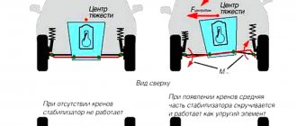
When a car turns, all its wheels travel different lengths, and if there is a rigid connection between the two driving wheels, they will begin to slip. Wheel slipping when turning leads to increased fuel consumption, tire wear, instability, etc.
The differential allows the driven shafts to rotate at different angular speeds and performs the functions of distributing the torque supplied to it between the wheels or drive axles. Differentials can be interwheel or interaxle (if installed between several drive axles).
The differential was first used in 1897. on a steam car. Currently, all cars have cross-axle differentials on drive axles. The most common is a symmetrical bevel differential, which includes: a housing, satellites, a satellite axis (or spider) and side gears. Typically, the number of satellites in the differentials of passenger cars is two, and four for trucks and off-road vehicles.
The symmetrical differential got its name for its ability to distribute the supplied torque equally at any ratio of the angular velocities of the shafts connected to it. The use of such a differential as a cross-axle differential ensures stability during straight-line movement, as well as during engine braking on a slippery road.
A significant disadvantage of a conventional differential is the reduction in the vehicle's maneuverability if one of its wheels encounters conditions of low adhesion to the supporting surface. At the same time, a wheel in normal adhesion conditions cannot be supplied with a torque exceeding that which can be realized on a wheel in conditions of low adhesion (this leads to wheel slipping). To overcome this disadvantage, some designs use differentials of all-wheel drive vehicles of various designs.
1) with electronic locking;
2) with disc differential;
3) with a viscous coupling.
The system is controlled both mechanically by the driver and with the help of special control units that take into account the angular speeds of the wheels and the difference in torque between the front and rear drive. Fully automatic systems save fuel, improve the vehicle's maneuverability, making it easier to control at high speed, and better utilize engine power.
Today, such systems of self-locking differentials have proven themselves to be the best; they are distinguished by their strength, reliability and durability, without requiring any complex maintenance and repairs during operation.
Application
Torsen self-locking differentials are used both as inter-wheel and inter-axle torque distribution devices. The Torsen Audi Quattro differential is widely known. In modern all-wheel drive vehicles, this mechanical device is installed quite often. Note that the Torsen center differential is used on almost all Hummer cars.
The popularity of the Thorsen torque vectoring device is due to the lack of communication with any electronics or clutches. This transmission element is a relatively simple mechanism, characterized by instantaneous operation and the absence of a negative impact on the braking process. That is why leading automakers use this type of differential in their cars.
A Torsen-type differential is a type of self-locking differential that operates on the basis of varying friction of mechanical parts, leading to a redistribution of torque between the wheels.
Purpose of a Torsen differential A differential is a device that transmits force from a single source (gearbox) to two wheel drives, and at the same time ensures independence (differentiation) of rotation of these drives. As a result, they can rotate at different angular speeds when cornering, when the inner wheel travels a shorter distance than the outer one. The simplest differential distributes power evenly between the wheels. Accordingly, when one wheel slips, the force on the second is zero. More advanced devices, the vast majority of which belong to the class of self-locking differentials or limited-slip differentials, are equipped with mechanisms that ensure that the suspended axle shaft is locked and force is redistributed so that maximum power is transferred to the wheel that maintains traction. The Torsen-type differential is considered the optimal solution for all-wheel drive vehicles operated in harsh conditions. Thorsen is not the name of the inventor, but an abbreviation for “Torque Sensing”, that is.
Torsen differential device
This mechanism was patented in the late 1950s in the USA and gave its name to the company of the same name. A self-locking differential is a device integrated into the vehicle system that supplies torque to the vehicle's drives. This is necessary to redistribute power from the transmission and engine to the wheels to improve cross-country ability. It is also called a torsen limited slip differential. It is widely used on vehicles with all-wheel drive and serves to block the power of the wheel when it slips and transfer it to the working drive. This effect allows the car to effortlessly overcome road obstacles in bad weather or under extreme road conditions compared to conventional vehicles. Typical situations in which this system is used are as follows:
The design features of the Thorsen center differential include:
Also, during its existence, this product has gone through the release of 3 generations. The current family is installed on many modern models.
Positive and negative qualities
Torsen is one of the best options for self-locking differentials and this is due to its following advantages:
- Operation in fully automatic mode without third-party intervention (there are no manual or electronic control mechanisms);
- Instant speed of blocking;
- Silence;
- Possibility of use both between axles and between wheels;
- Smooth operation;
- Maintenance of the unit comes down to timely replacement of lubricant.
But at the same time, this unit also has many disadvantages. The entire operating principle of Torsen is based on the frictional force generated in worm gears under certain conditions. And this leads to a decrease in the overall efficiency of the unit and accelerated wear of working elements.
Another weak point that all worm differentials have is diagonal hanging, with which they become absolutely helpless.
In addition, Torsen is an expensive unit due to the complexity of manufacturing and the need to use high-strength materials.
Purpose
So, what is this mechanism for? The simplest differential is capable of distributing power or torque between two wheels equally, evenly. If one wheel slips and cannot grip the road surface, then the torque on the second wheel will be zero. Improved models, and the vast majority of them are differentials with a self-locking mechanism, are equipped with a system that blocks the suspended axle shaft. Then the torque is distributed so that the maximum power is on the wheel that maintains good grip.
You may be interested in: Where is the VAZ-2112 starter relay located? Location, purpose, replacement and device
You may be interested in: Band brake: device, principle of operation, adjustment and repair
The Thorsen differential is the most optimal solution for an all-wheel drive vehicle, which is operated mostly in difficult conditions. “Thorsen” is not the name of the developer, but an abbreviation. This stands for Torque Sensing.
Three types of “Torsen”
In the first option, gears of the driving axle shafts, as well as satellites, are used as worm pairs. Each axle axis has its own satellites, connected in pairs with those on the opposite axis. This connection is carried out using spur gearing. The axes of the satellites are perpendicular to the semi-axes. This version of the Thorsen differential is recognized as the most powerful among all similar designs. It is capable of operating over a very wide torque range.
The second option differs in that the axes of the satellites are parallel to the axle axes. The satellites in this case are installed differently. They are located in special seats of the cup. The paired satellites are connected by a helical gearing, which, when wedging, participates in blocking.
The third option is the only one among the entire series where the design is planetary. It is used as a center differential in all-wheel drive vehicles. The axes of the satellites and the drive gears are also parallel to each other here. Due to this, the unit is very compact. Thanks to the design, it is initially possible to distribute the load between two bridges in a ratio of 40:60. If partial blocking is triggered, the proportion may deviate by 20%.
Generations of Torsen differential
The Torsen self-locking differential has three generations:
- T-1 is the first generation of self-locking torque distribution device. In it, satellites and gears of the driving axle shafts act as worm pairs. The satellites of the axle shafts are connected by spur gearing. The axes of the satellites are perpendicular to the semi-axes. The first generation Thorsen cross-axle differential allows the car's wheels to rotate at different speeds. When a wheel slips, the mechanism tries to transfer most of the car engine power to another axle shaft, after which the worm pair of this axle shaft becomes wedged. In this case, the friction force that arises in the worm gear due to the difference in torque values on the wheels blocks the differential. The first generation of Torsen differential is the most powerful of all designs in its class.
- T-2 is the second generation of the device. The main differences from the first generation: the axes of the satellites here are located along the semi-axes; the satellites themselves are located in special pockets of the differential housing; The gears of the paired satellites participating in the process of blocking the mechanism when wedging are helical.
- T-3 is the third generation of differential. Has a planetary design. The third generation of Thorsen is used mainly as a center differential on vehicles with all-wheel drive. The mechanism has compact dimensions due to the fact that the drive gear and the axes of the satellites are located parallel in the structure.
For the future and fuel economy: Quattro Ultra
In 2022, Audi introduced a new type of all-wheel drive: Quattro ultra, which was first used on the Audi A4 allroad in mid-2022. It is noteworthy that previously the ultra prefix was not applied to drive types, but to Audi models, which were particularly economical. These models are intended mainly for economical Europe. The Quattro ultra all-wheel drive is actually designed to further reduce fuel economy by reducing transmission losses. Quattro ultra can only be combined with 2-liter engines in combination with a manual transmission or S tronic automatic transmission.
So, Quattro ultra is a permanent all-wheel drive that actively regulates the torque supplied to the rear axle. At the heart of this transmission is an electronically controlled multi-plate clutch with hydraulic drive. It is docked to the gearbox. Another clutch – with a cam actuator – is integrated into the rear final drive.
The peculiarity of the Quattro ultra drive is the interaction of the all-wheel drive clutch with the dog clutch in the rear final drive. It allows you to immobilize the transfer case (main pair) with the rear axle drive shaft when the all-wheel drive clutch is open, separating them from the rest of the transmission. When both clutches open, the rear axle drive shaft and rear final drive parts become stationary, reducing friction losses. This significantly saves fuel and reduces CO2 emissions. Savings of 0.3 l/100 km are promised.
The Quattro ultra all-wheel drive clutch distributes torque in a free proportion. When all-wheel drive is not needed and the need for it is not expected in the near future, it switches to front-wheel drive, which is more efficient in terms of fuel consumption.
In this case, the all-wheel drive clutch is first opened and the driving performance of the vehicle is assessed when driving on front-wheel drive only. If the ride quality is stable, the dog clutch in the rear final drive opens.
The all-wheel drive control unit constantly monitors the parameters of wheel rotation and acceleration and allows you to predict the car going into a skid 500 ms before the onset of this negative situation. These 500 ms are enough for the Quattro ultra actuators to activate all-wheel drive.
To engage all-wheel drive, the dog clutch in the rear final drive must close again. It is impossible to turn it on instantly, since in front-wheel drive mode the rear differential box is motionless. It needs to be “spinned up” and the speed of its rotation must be synchronized. Therefore, when all-wheel drive is engaged, the all-wheel drive clutch first closes, accelerating the driveshaft and the rear final drive driven gear connected to it. When the rotation speed of the rear differential box has become approximately synchronous, the dog clutch is activated.
Differential lock and stability control
Forced differential lock with hydraulic drive
In order for the torque of the axle shafts to become the same again, it is necessary to block the action of the satellites or ensure its transmission from the cup to the loaded axle shaft.
This is especially true for off-road vehicles with 4X4 all-wheel drive. Not only because they are designed for driving in areas with difficult road conditions. If a car equipped with three differentials (two interwheel, one center) loses grip at least at one of the four points, the torque of the remaining wheels will go to zero, and the car will refuse to move.
Locking helps to avoid troubles, which can be either partial or complete (depending on the degree of redistribution of forces between the axle shafts), as well as either manual or automatic (depending on the degree of control on the part of the driver).
They have proven themselves well, distributing torque, taking into account its difference on the axle shafts or based on the values of angular velocities.
The most complex and perfect way to eliminate the shortcomings of the unit is an electronic lock, implemented on the basis, the sensors of which monitor all the necessary parameters while the car is moving. Based on the data received, the vehicle’s operation is adjusted automatically.
Device and main components
Audi Quattro
Let's look at what basic elements Thorsen consists of:
- Housing (other name: “differential cup”). It transmits torque from the main gear to the side gears through the satellites. The driven gear of the main gear is mounted on it. Inside the differential cup there are axles on which the satellites are mounted.
- Right and left side gears (other name: “sun gears”). They transmit torque to the axles/half shafts through a spline connection.
- Satellites of the right and left semi-axial gears. The differential cup and side gears are connected. Thorsen has four satellites in its design.
- Output shafts.
Note that this type of self-locking differential has the most advanced design.
Advantages and disadvantages
Let's start with the advantages of the Torsen differential:
- high precision work
- smooth operation
- low noise level during operation
- The distribution of vehicle engine power between the wheels or drive axles occurs automatically and does not require driver participation
- instant redistribution of torque does not affect the braking process
- with correct operation, practically no maintenance is required (only monitoring the transmission oil level and its timely replacement are necessary)
Disadvantages of the Thorsen differential:
However, if you love cars and technology, the countless and varied ways to do so are exciting and knowing that they can make you a better driver. So to start with this wheel issue, what do I need to get all 4 wheels to drive my car?
You basically need 3 things for this.
- Front differential rear differential.
- One way to connect to two.
This is called speed offset, and the same principle applies to the front and rear axles, as shown here. As you can see, the inside wheel moves less distance when cornering than the outside wheel, and the same goes for the front and rear axles.
- high cost due to the complexity of manufacturing and assembling the mechanism
- increased fuel consumption due to friction losses of mechanical device elements
- relatively low efficiency
- predisposition to jamming
- high wear of loaded elements
- the mechanism requires special lubricants due to significant heat generation during operation
- accelerated wear of parts when using wheels of the same axle with different characteristics (for example, when installing a spare wheel that differs from the installed wheels)
Differential Thorsen
Today I want to present to you the famous Thorsen differential and its generations.
The Torsen differential is a type of self-locking differential that operates on the basis of varying friction of mechanical parts, leading to a redistribution of torque between the wheels. Differential is a device that transmits force from a single source (gearbox) to two wheel drives, and at the same time ensures independence (differentiation) of rotation of these drives. As a result, the wheels of the same axle can rotate at different angular speeds when cornering, when the inner wheel travels a shorter distance than the outer one. The simplest differential distributes power evenly between the wheels. Accordingly, when one wheel slips, the force on the second is zero. More advanced devices, the vast majority of which belong to the class of self-locking differentials or limited slip differentials, are equipped with mechanisms that ensure blocking of the “hung” axle shaft and redistribution of force so that maximum power is transferred to the wheel that maintains traction.
The Torsen differential is considered the optimal solution for all-wheel drive vehicles operating in harsh conditions. Thorsen is not the name of the inventor, but an abbreviation for “Torque Sensing,” that is, “sensitivity to torque.”
The history of the Torsen differential
The schematic diagram of this type of Torsen differential was invented in 1958 by the American engineer Vernon Glizman. The patent for the production of a self-locking mechanical differential of this type is held by Torsen, whose name became the name of the type of limited-slip differential.
Design and principle of operation of a Torsen differential
If in a classic differential all drives are bevel, then in “torsens” there are worm gears. Due to the mechanical property of the worm gear to “wedge” at a certain torque ratio, the slipping wheel is blocked, and without the use of electronics that reduce the overall reliability, up to 83% of the power is “transferred” to the impeller. Thus, unlike the classic design, Thorsen does not equalize the torque on the wheels, but directs it to the “loaded” axle shaft.
Generation of Torsen differentials
In the first
(T-1), the worm pairs are the drive axle gears and satellites. Each axle shaft has its own satellites, which are connected in pairs with the satellites of the opposite axle shaft by a conventional spur gear. The satellite axis is perpendicular to the semi-axis. When turning, the semi-axial gear connected to the lagging wheel turns the satellite engaged with it, which, in turn, rotates the second satellite and another semi-axial gear. This sequence allows the car's wheels to rotate at different speeds. But when slipping, when the differential tries to transfer most of the power to one of the axle shafts, the worm pair of this axle shaft begins to wedge, and the friction forces arising in the worm gear from the difference in torques on the wheels lock the differential. Torsen Type 1 is the most powerful design in the class because it operates over the widest range of torque ratios, from 2.5/1 to 5.0/1.
In the second Torsen
(T-2) the axes of the satellites are parallel to the semi-axes. The satellites are located in special pockets of the differential cup. The paired satellites have helical gearing, which, when wedged, also participates in the blocking process.
In the third Torsen
(T-3) is the only one in the series with a planetary design. Used primarily as a center differential in all-wheel drive vehicles. The axes of the satellites and drive gear are also parallel, which is why the entire assembly is quite compact. The T-3 design allows you to initially redistribute the load between the bridges - usually 40/60. Partial blocking occurs when there is a deviation from this proportion of 20-30%.
Pros and cons of a Torsen differential
Among the main disadvantages of limited slip differentials, which include Torsen, are relatively low efficiency and increased fuel consumption due to high friction losses, as well as high wear of loaded parts and a tendency to jam. In addition, the significant heat generation of differentials of this type requires special measures for its cooling and special lubricants. The advantages of “torsens” include smoothness and high accuracy of operation, as well as a relatively low noise level. And, of course, the fact that the fight against road troubles does not require any special body movements from the driver - the distribution of engine power between the wheels occurs automatically.
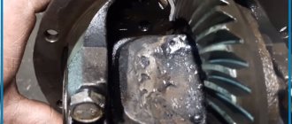
Torsen differentials, as a rule, do not require maintenance when used correctly. For their reliable operation, it is enough to regularly change the transmission oil and monitor its level. If signs of wear appear (most often this is the characteristic noise of the gearbox), it is better to replace the entire assembly, since “amateur” replacement of individual parts can cause failure of the entire transmission. It is also necessary to remember that rapid wear of a differential with a worm pair can be caused by driving with different characteristics of wheels on the same axle - for example, using a “non-standard” spare wheel.
Source
"Haldex"
THIS NAME is derived from the name of the Swedish company “Haldex”, which was the first in the world to develop and patent a differential based on an electronically controlled multi-plate clutch. Recently, such devices have become more and more popular. Moreover, the vast majority of automakers use differentials on their models produced directly by Haldex. The fact is that such couplings are produced in the form of a single unit, easily adaptable for installation on almost any car.
In its design, the Haldex coupling is partly similar to a visco coupling, but differs from it in its operating principle. In the Swedish device, blocking is done not by changing the properties of the liquid poured into the body, but by compressing the disks using an electronically controlled hydraulic drive. For example, if the sensors detect that one differential shaft has begun to rotate faster, the control unit immediately commands the electric pump to increase the pressure in the system and press one disk against the other. Thus, “Haldex” is blocked. And by adjusting the compression force of the disks, the electronic unit also controls the degree of clutch locking.
Relatively low cost, minimal delays in operation and flexibility of settings are the main advantages of the Haldex type hydraulic multi-plate clutch. Therefore, on modern cars such devices are widely used both in conjunction with a conventional differential (to lock it) and instead of it (for example, to connect all-wheel drive on many SUVs). Nissan X-Trail, Renault Koleos, VW Tiguan, Mitsubishi Outlander XL, Toyota RAV4, Audi TT, Audi A3, etc. can boast of such a transmission, based on a multi-plate hydraulic clutch. VW Golf 4Motion” and, naturally, all all-wheel drive “Volvo” models.