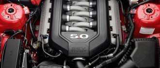
An injector is a kind of system that is designed to transport fuel into the cylinders of a car. For this purpose, injectors are used, which receive an electronic signal from the vehicle's control unit. It is worth noting that fuel supply is carried out exclusively by a point method. The injection system is considered quite common today. These designs are significantly more modified versions of the carburetor.
It is worth noting that the first such system was developed at the end of the 19th century. But the introduction into the automotive industry itself occurred only in the second half of the 20th century. The fact is that experts considered this mechanism to be too complex and unreasonably expensive.
Today, all modern engines equipped with fuel injection systems operating on a point-by-point supply of fuel to the cylinders are manufactured with special electronic control units. An alternative could be a controller or engine management system. But, in any case, all these devices are computer devices. They provide the injection system with the necessary information, on the basis of which it can operate, adjust the fuel dose, injection frequency, and more.
When did the injector appear?
The carburetor, apparently, has already mixed the amount of fuel allocated to it with air in the 20th century and its time is rapidly coming to an end. Despite the fact that the fuel injection system appeared much earlier than the carburetor, it is just beginning to take root under the hoods of cars. The injection owes its origin to the Italian physicist and inventor Giovanni Venturi, who invented an injector with a variable cross-section and modestly called it the Venturi Tube.
The guys from Leon Levassor's garage started using it in cars. They installed something like modern injection on their cars back in 1902. After that, automotive power systems rushed about in search of a better device, and the injector found application in aircraft engines. By the end of the 40s, all military fighters used an injection power system until military aviation switched to jet propulsion.
Central fuel injection
Single injection is the simplest mechanism. The second name is central injection. And he was the first in history. It was widely used in the USA at the beginning of the 2nd half of the 20th century. How does central injection work? Simplicity is exactly what appealed not only to car owners, but also to manufacturers. The design is very similar to a carburetor, only a nozzle is used instead.
It is installed on the intake manifold - one for all engine cylinders, regardless of their total number. Fuel enters the manifold constantly, as does air. As a result, a fuel-air mixture is formed, which is distributed among the cylinders.
Main advantages of the injection system
Modern experts note several advantages of these types of fuel supply systems. Namely:
- It was possible to achieve a significant reduction in fuel consumption. This became possible thanks to precise control of fuel supply.
- This system helps increase power. For comparison, carburetor internal combustion engines have an average power of 10% less than identical injection engines.
- Automated injection system. It is worth remembering that in carburetor cars, the adjustment function is performed by the suction and adjusting screws. In this case, the driver does not have to waste time, and the system will do everything for him.
Advantages and disadvantages
The advantages of a central injection system:
- simplicity and low cost of design;
- To change operating modes, it is enough to adjust one nozzle;
- When changing a carburetor to an injector (single injection), no significant changes are made to the power system.
The disadvantages include the fact that it is not possible to achieve high levels of environmental friendliness. Therefore, today cars with single injection cannot be found for sale and operation in developed countries of America, Europe and Asia. Unless in third world countries they will travel freely on the roads.
And the biggest inconvenience is that if the injector fails, the engine stops and it is impossible to start it.
Variety of injection systems
In modern times, there are two types of injectors. The first refers to mono-injection systems. In this case, one injector supplies fuel to the manifold to all cylinders. Among motorists, such a system is better known as an electronic carburetor. However, modern manufacturers have already moved away from this technology, and a similar system can only be found in older models.
The second system involves distributed injection, that is, multipoint injection. In this case, a separate injector is installed in the intake tract of each cylinder and each of them supplies a certain volume of fuel into the combustion chamber.
Based on the method of injection distribution, such systems are divided into:
- Simultaneous. The system is very rare, but still occurs. Its peculiarity is that in just one revolution of the crankshaft, absolutely all injectors fire at the same time.
- Pairwise parallel. In this case, the injectors work in pairs. In other words, only one pair of injectors operates per revolution of the crankshaft.
- Consistent. This type of injection distribution is the most common. A special feature is that for one revolution of the shaft, each injector opens once before the intake stroke. In this case, the adjustment occurs separately.
Types and types of injectors
There are two types of injectors:
- With single point injection. This system is outdated and is no longer used on cars. Its essence is that there is only one nozzle, installed in the intake manifold. This design did not ensure uniform distribution of fuel throughout the cylinders, so its operation was similar to a carburetor system.
- Multipoint injection. Modern cars use this type. Here, each cylinder has its own nozzle, so this system is characterized by high dosage accuracy. Injectors can be installed both in the intake manifold and in the cylinder itself (direct injection system).
A multipoint fuel injection system can use several types of injection:
- Simultaneous. In this type, an impulse from the ECU is sent to all injectors at once, and they open together. This type of injection is not currently used.
- Paired, also known as pairwise-parallel. In this type, the injectors work in pairs. It is interesting that only one of them supplies fuel directly during the intake stroke, while the second does not have the same stroke. But since the engine is a 4-stroke, with a valve timing system, the mismatch of injection on the stroke does not affect the performance of the engine.
- Phased. In this type, the ECU sends signals to open for each injector separately, so injection occurs with a coincident timing.
It is noteworthy that a modern fuel injection system can use several types of injection. So, in normal mode, phased injection is used, but in the event of a transition to emergency operation (for example, one of the sensors has failed), the injection engine switches to twin injection.
Negative characteristics of systems
Despite the huge list of positive characteristics, this mechanism, like many others, also has its dark side. The disadvantages of this design include:
- quite high cost of repairs;
- high cost of components;
- low probability of repair;
- high requirements for fuel quality;
- Only a professional can determine the malfunction;
- diagnostics are quite expensive;
- For repairs you need to have special equipment.
It is worth noting that the injection type of fuel injection over time can lead to the intake valve becoming coked. This is due to the fact that it is simply not washed with fuel, which, in some way, cleans it.
Advantages and disadvantages
The injector has gained immense popularity in the modern world. This is due to the following advantages:
- The operating mode changes automatically, without the use of the human factor;
- There is absolutely no need for manual configuration;
- The engine is very economical;
- Fully complies with all environmental standards;
- Very easy to start in any weather, no loss of power.
Of course, there are no shortcomings. They are also worth talking about:
- Quite high cost and maintenance;
- Many parts are beyond repair. That is, they will have to be completely thrown out and replaced with new ones;
- It is almost impossible to carry out repairs and maintenance at home. This requires special equipment and experience;
- The motor is very dependent on the mains voltage.
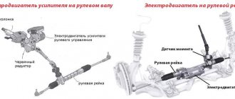
System design
The fuel injection system consists of electronic and mechanical components. The first controls the operating parameters of the power unit and, based on them, sends signals to activate the executive (mechanical) part.
The electronic component includes a microcontroller (electronic control unit) and a large number of tracking sensors:
- Lambda probe;
- crankshaft position;
- mass air flow;
- throttle position;
- detonation;
- coolant temperature;
- air pressure in the intake manifold.
Injector system sensors
Some cars may have several additional sensors. They all have one task - to determine the operating parameters of the power unit and transmit them to the ECU
As for the mechanical part, it includes the following elements:
- tank;
- electric fuel pump;
- fuel lines;
- filter;
- pressure regulator;
- fuel rail;
- injectors.
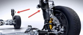
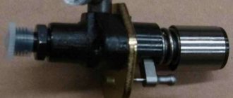
Simple fuel injection system
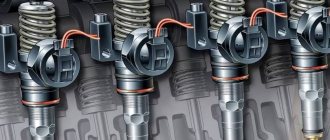
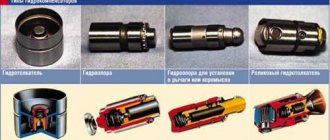
Types of injection nozzles
Injection nozzles differ in injection methods:
- Electromagnetic;
- Electrohydraulic;
- Piezoelectric.
An electromagnetic injector is quite simple and is installed on gasoline engines (in most cases). It is also equipped with engines with direct injection. Its main components are a solenoid valve equipped with a needle, as well as a nozzle. During operation, an electric discharge is applied to the valve winding. The frequency of its supply is controlled by a special electronic control unit. During the process, an electromagnetic field is formed. It retracts the needle, releases the nozzle and injection occurs, and this is done simultaneously with compression of the spring, which expands after the disappearance of the electromagnetic field and returns the needle to its original position.
Electro-hydraulic injector – used on diesel engines (including those with the Common Rail system). The main elements of this injector are the control chamber, throttles (inlet and drain) and the solenoid valve. They work due to the difference in diesel pressure on the injector and the piston: the fuel injector needle is pressed against the seat, while the solenoid valve is closed (de-energized).
When the control unit opens the valve, the throttle (drain) also opens. Next, the fuel line is filled with diesel fuel flowing through the throttle. At the same time, the diesel fuel pressure on the piston begins to decrease, while on the needle it remains the same. Because of this, the needle rises and injection occurs.
The piezoelectric injector is the most advanced (technically speaking) option. As a rule, diesel engines are equipped with it. It has many advantages, including speed of operation (compared to an electromagnetic device, it is 4 times faster), as well as extremely accurate and verified dosage. In this case, a piezoelectric crystal is used, which changes its length under voltage. This device consists of a pusher, a piezoelectric element, a valve and a needle.
The operating principle is similar to an electrohydraulic nozzle. A scheme with a difference in fuel pressure is also used here. The electric current extends the piezoelectric element, which presses on the pusher. As a result, the switching valve opens and fuel flows into the line. The pressure on the needle decreases and it moves upward, producing an injection.
How it all works
Now let’s look at the principle of operation of an injection engine separately for each component. With the electronic part, in general, everything is simple. The sensors collect information about the speed of rotation of the crankshaft, air (entered into the cylinders, as well as its residual part in the exhaust gases), throttle position (connected to the accelerator pedal), and coolant temperature. The sensors constantly transmit this data to the electronic unit, due to which high accuracy of gasoline dosage is achieved.
The ECU compares the information received from the sensors with the data entered in the maps, and based on this comparison and a series of calculations, it controls the executive part. The electronic unit contains so-called maps with optimal operating parameters of the power plant (for example, for such conditions it is necessary to submit as many - so much gasoline, for others - so much).
Toyota's first fuel-injected engine in 1973
To make it clearer, let us consider in more detail the algorithm of operation of the electronic unit, but according to a simplified scheme, since in reality a very large amount of data is used in the calculation. In general, all this is aimed at calculating the time length of the electrical pulse that is supplied to the injectors.
Since the diagram is simplified, we assume that the electronic unit carries out calculations only on several parameters, namely the base time pulse length and two coefficients - coolant temperature and oxygen level in the exhaust gases. To obtain the result, the ECU uses a formula in which all available data is multiplied.
To obtain the basic pulse length, the microcontroller takes two parameters - the crankshaft rotation speed and the load, which can be calculated from the pressure in the manifold.
For example, the engine speed is 3000, and the load is 4. The microcontroller takes this data and compares it with the table included in the card. In this case, we get a basic pulse length of 12 milliseconds.
But for calculations it is also necessary to take into account the coefficients, for which readings are taken from the coolant temperature sensors and the lambda probe. For example, the temperature is 100 degrees, and the oxygen level in the exhaust gases is 3. The ECU takes this data and compares it with several more tables. Let's assume that the temperature coefficient is 0.8 and the oxygen coefficient is 1.0.
Having received all the necessary data, the electronic unit carries out the calculation. In our case, 12 is multiplied by 0.8 and 1.0. As a result, we find that the pulse should be 9.6 milliseconds.
The described algorithm is very simplified, but in reality, more than a dozen parameters and indicators can be taken into account in the calculations.
Since data is constantly supplied to the electronic unit, the system almost instantly reacts to changes in engine operating parameters and adapts to them, ensuring optimal mixture formation.
It is worth noting that the electronic unit controls not only the fuel supply, its task is also to adjust the ignition angle to ensure optimal engine operation.
Now about the mechanical part. Everything is very simple here: a pump installed in the tank pumps gasoline into the system, under pressure, to ensure forced supply. The pressure must be certain, so a regulator is included in the circuit.
Gasoline is supplied through the highways to a ramp, which connects all the injectors. An electrical impulse supplied from the ECU causes the injectors to open, and since gasoline is under pressure, it is simply injected through the opened channel.
Catalytic converter
This device allows you to reduce the content of substances such as carbon monoxide and nitrogen in the exhaust gases by converting them into hydrocarbons. It is not controlled by the ECU, but interacts with the processing center through a sensor that determines the percentage of oxygen in the exhaust accumulations. If there is excess fuel supply, the controller receives information from the sensor and corrects it.
The converter contains ceramic elements with built-in catalysts:
- oxidative (platinum and palladium);
- restorative rhodium;
- selective;
- cumulative.
Note: leaded gasoline is detrimental to the operation of neutralizers, and refueling substances with a high sulfur content will render the elements of accumulative catalysis unusable!
Why is an injector better than a carburetor?
I remember that until relatively recently, cars with fuel injection systems caused mistrust. Perhaps the only logical explanation for this is the complexity of its design, which caused problems with repairs at first. Unlike a carburetor, fuel injection in an injector does not need to be adjusted, since this is the responsibility of the electronic control system. In addition, a car with an injection unit consumes less fuel, and its engine power is much higher. Plus, there is a significant reduction in harmful compounds in car exhaust, due to better combustion of the fuel mixture, which is possible thanks to its correct and dosed supply.
Injector types
1. The central fuel supply system (mono-injection) is represented by one nozzle, through which the fuel mixture enters the manifold, and from it is distributed to all cylinders. The simplest type, which is practically not used today.
2. Distributed fuel supply system (multipoint injection). Here, fuel is injected into the cylinders through individual injectors, that is, the number of injectors corresponds to the number of cylinders.
A multipoint injection system is:
— Simultaneous type, when all injectors open and fuel is injected during one full revolution of the crankshaft. Almost never occurs.
— Pair-parallel type, when fuel injection is carried out through paired injectors, the operating cycle of which is determined by one rotation of the crankshaft. It is also rarely used, however, it may occur due to sensor failure with a sequential type of fuel supply.
— With sequential (phased) fuel injection, in which each of the injectors opens for fuel injection during one rotation of the crankshaft. The most common and advanced fuel injection system, which allows the working mixture to be supplied directly to the cylinder, while the duration of its supply and dosage are calculated as accurately as possible. It is worth noting that the operating pressure of the system can increase to 200 atm.
However, there are also a number of disadvantages, which include the presence of many expensive elements, some of which are absolutely irreparable. Also, in injectors with a sequential fuel injection system, the intake valves very often become coked, due to the fact that they are practically not washed, and therefore are not cleaned by the fuel mixture.
Something else interesting
It is worth paying attention to the fact that, unlike carburetor systems, injection systems require regular checking of the fuel system. This is because a large number of complex electronics can fail. As a result, this will lead to undesirable consequences. For example, excess air in the fuel system will lead to a violation of the emulsion composition and an incorrect mixture ratio. In the future, this affects the engine, unstable operation appears, controllers fail, etc. Essentially, an injector is a complex system that determines when a spark needs to be applied to the cylinders, how to deliver a high-quality mixture to the cylinder block or intake manifold, when to open the injectors and what ratio of air to gasoline should be in the emulsion. All these factors affect the synchronized operation of the fuel system. The interesting thing is that without most of the controllers, the machine can work properly, and there will be no significant deviations, since there are emergency records and tables that will be used.
The efficiency of the internal combustion engine in our case is determined by how correct the data received from the controllers will be. The more accurate they are, the less likely various fuel system malfunctions are. The speed of operation of the system as a whole also plays an important role. Unlike carburetors, manual adjustment is not required, and this eliminates errors during calibration work. Consequently, we will get more complete combustion of the mixture and a better system from an environmental point of view.
Types of injection systems for gasoline engines
The injection can be:
- central (internal combustion engine with carburetors, over-throttle injection),
- distributed or manifold (carried out by a separate injector in each engine cylinder),
- direct (carried out directly into the combustion chambers, using separate nozzles), found in different variations, typical of modern cars.
Variants of fuel systems for gasoline engines (R R. Bosch)
Carburetor solutions
For the longest time, humanity has been familiar with the supply of fuel through a carburetor. And not because such solutions are the best, but because they are the first. And many years are the only ones available. The carburetor has been an integral part of the fuel system for about a hundred years. It cannot be said that carburetors have now completely disappeared from life, but they have stopped installing carburetors on passenger and commercial vehicles. They can only be seen on mechanization equipment that is used for gardening and construction work. The auto industry stopped producing cars with a carburetor system back in the 90s of the last century.
The principle of their operation is based on the principle of drawing fuel into the air flow passing through the carburetor. All this is possible due to the narrowing of the air channel and rarefaction of the air.
The volume of air that passes through the narrowing of the air channel is proportional to the volume of fuel entering through the carburetor nozzle. Thanks to this, it is easy to automatically maintain the required fuel-to-air ratio.
How does the device work?
- Fuel is taken from the tank by a pump (mechanically or electrically controlled, depending on the model).
- The internal combustion engine starts, and the air flow passing through the narrowing of the carburetor air channel creates a vacuum.
- Fuel enters the carburetor mixing chamber.
- The jet (calibrated hole) dispenses fuel.
From a work point of view, everything is quite simple. So why are carburetors becoming a thing of history? There are quite a few reasons:
- Low efficiency and, accordingly, low fuel efficiency.
- Problems with variable operating modes caused by low dynamic qualities.
- Direct dependence on the position of the engine.
- Release of a large amount of harmful substances into the environment (non-compliance with standards for the emission of gaseous harmful emissions into the atmosphere).
Features of the injection system
The main advantage of the injection system is the precise dosage of fuel required for optimal engine operation at a certain moment and under a certain load. This was achieved only by an electronic control system. Old injection systems were mechanically controlled and supplied gasoline according to the average needs of the engine. A modern injector is able to accurately calculate how much fuel is needed and at what moment it needs to be supplied. Synchronizing the power system with the ignition allows you to quickly change both the spark advance angle and the timing of gasoline supply, therefore, theoretically, injection systems should be more efficient and economical than carburetor systems.
Diagnostics of injection systems
Indeed, with the use of electronics and a distributed injection system, engines have become a little more economical, but you can’t argue with physics, and without the required amount of gasoline, the combustion chamber simply will not produce the energy that is needed. With the increasing complexity of injection systems, new problems began to appear, especially on cheap cars, since the injection system is very demanding on the materials of the fuel equipment and especially on the quality of the fuel. This is generally a sore point for all injectors. The amount of sulfur in domestic gasoline does not meet any standards, so even inexpensive injection systems often require the intervention of a mechanic.
Malfunctions of the injection system manifest themselves in different ways, but diagnostic methods at modern service stations make it possible to fairly accurately determine the non-working element. Most often, it is the fuel pumps and injectors that suffer. It’s easy to determine the fault; you don’t even need to go to a service center to do it:
- hard start;
- high consumption;
- failures in operation at medium speeds and lack of idle;
- failures in transient conditions.
All this indicates an insufficient amount of gasoline in the combustion chamber. Pumps, as a rule, are not repaired, at least not by official services, and the injectors have to be washed and cleaned.
Operating principle of the direct injection system
As a result of its operation, the direct injection system provides several types of mixture formation:
- layered ;
- stoichiometric homogeneous;
- homogeneous.
The diversity in mixture formation determines the high efficiency of fuel use (savings, quality of mixture formation, its complete combustion, increased power, reduced harmful emissions) in all engine operating modes.
Layer-by-layer mixture formation is used when the engine operates at low and medium speeds and loads. Stoichiometric (another name is flammable) homogeneous (another name is homogeneous) mixture formation is used at high engine speeds and heavy loads. With a lean homogeneous mixture, the engine operates in intermediate modes.
With layer-by-layer mixture formation, the throttle valve is almost completely open, the intake flaps are closed. Air enters the combustion chambers at high speed, forming an air vortex. Fuel is injected into the spark plug area at the end of the compression stroke. For a short time before ignition, a fuel-air mixture with an excess air ratio of 1.5 to 3 is formed in the area of the spark plug. When the mixture ignites, quite a lot of clean air remains around it, acting as a heat insulator.
The working process is supported by the movement of air in the cylinders. Depending on the load and speed modes, the intensity of air movement is regulated, while ensuring the creation of a homogeneous or layer-by-layer mixture.
Homogeneous stoichiometric mixture formation occurs when the intake flaps are open, and the throttle valve opens in accordance with the position of the gas pedal. Fuel injection is carried out during the intake stroke, which contributes to the formation of a homogeneous mixture. The excess air coefficient is 1. The mixture ignites and burns efficiently throughout the entire volume of the combustion chamber.
A lean, homogeneous mixture is formed with the throttle valve wide open and the intake flaps closed. This creates intense air movement in the cylinders. Fuel injection occurs on the intake stroke. The excess air ratio is maintained by the engine management system at 1.5. If necessary, exhaust gases from the exhaust system are added to the mixture, the content of which can reach up to 25%.
Features of fuel equipment
The car has always been the object of attention of environmentalists. Exhaust gases are released directly into the atmosphere, which can cause pollution. Diagnostics of the fuel system showed that the amount of emissions due to incorrect mixture formation increases significantly. For this simple reason, it was decided to install a catalytic converter. However, this device showed good results only with a high-quality emulsion, and in case of any deviations, its effectiveness dropped significantly. It was decided to replace the carburetor with a more accurate injection system, which was an injector. The first options included a large number of mechanical components and, according to research, such a system became worse and worse as the vehicle was used. This was quite natural, since important components and working parts became dirty and failed.
In order for the injection system to be able to correct itself, an electronic control unit (ECU) was created. Along with the built-in lambda probe, which is located in front of the catalytic converter, this gave good performance. It’s safe to say that fuel prices today are quite high, and the injector is good because it allows you to save gasoline or diesel. In addition to this, there are the following advantages:
- Increased engine performance. In particular, increased power by 5-10%.
- Improving the dynamic performance of the vehicle. The injector is more sensitive to changes in loads and itself adjusts the composition of the emulsion.
- The optimal fuel-air mixture reduces the amount and toxicity of exhaust gases.
- The injection system starts easily regardless of weather conditions, which is a significant advantage over carburetor engines.
Flushing the injection system
There are several ways to clean the injection system. If the engine is not yet in critical condition, then flushing with fuel additives can help. They dissolve deposits in the pump, fuel line, and most importantly, in the injectors, and to some extent clean the system of dirt and toxins. This is not always possible and it is not always safe for the engine, so ultrasonic baths are considered the most effective way to clean injectors. This is not a mechanical cleaning method and the process is quite effective.
The fuel injection system continues to improve, completely replacing carburetors. The systems are quite functional, but in order to avoid unnecessary problems with cleaning and adjustments, it is worth monitoring the quality of the fuel exactly as much as our oil refineries allow. Clean gasoline to everyone, and good luck on the road!
Sensor feedback
One of the main sensors, based on the readings of which the computer regulates the opening time of the injectors, is the lambda probe installed in the exhaust system. This sensor determines the residual (unburnt) amount of air in the gases.
Thanks to this sensor, so-called “feedback” is provided. Its essence is this: the ECU carried out all the calculations and sent an impulse to the injectors. The fuel entered, mixed with air and burned. The resulting exhaust gases with unburned mixture particles are removed from the cylinders through the exhaust gas exhaust system, in which a lambda probe is installed. Based on its readings, the ECU determines whether all calculations were carried out correctly and, if necessary, makes adjustments to obtain the optimal composition. That is, based on the already completed stage of fuel supply and combustion, the microcontroller makes calculations for the next one.
It is worth noting that during the operation of the power plant, there are certain modes in which the readings of the oxygen sensor will be incorrect, which can disrupt the operation of the engine or a mixture with a certain composition is required. In such modes, the ECU ignores information from the lambda probe, and it sends signals to supply gasoline based on the information stored in the cards.
In different modes, feedback works like this:
- Start the engine. In order for the engine to start, you need an enriched fuel mixture with an increased percentage of fuel. And the electronic unit provides this, and for this it uses the specified data, and it does not use information from the oxygen sensor;
- Warm up In order for the injection engine to reach operating temperature faster, the ECU sets increased engine speeds. At the same time, it constantly monitors its temperature, and as it warms up, it adjusts the composition of the combustible mixture, gradually depleting it until its composition becomes optimal. In this mode, the electronic unit continues to use the data specified in the maps, still not using the lambda probe readings;
- Idling. In this mode, the engine is already completely warmed up, and the temperature of the exhaust gases is high, so the conditions for the correct operation of the lambda probe are met. The ECU is already starting to use the readings of the oxygen sensor, which makes it possible to establish the stoichiometric composition of the mixture. With this composition, the greatest power output of the power plant is ensured;
- Movement with a smooth change in engine speed. To achieve economical fuel consumption at maximum power output, a mixture with a stoichiometric composition is needed, therefore, in this mode, the ECU regulates the supply of gasoline based on the readings of the lambda probe;
- A sharp increase in speed. In order for an injection engine to respond normally to such an action, a slightly enriched mixture is needed. To ensure this, the ECU uses map data rather than lambda probe readings;
- Motor braking. Since this mode does not require power output from the engine, it is enough that the mixture simply does not allow the power plant to stop, and a lean mixture is also suitable for this. To display it, the lambda probe readings are not needed, so the ECU does not use them.
As you can see, although the lambda probe is very important for the operation of the system, the information from it is not always used.
Injection engine sensor system
Without these components, the operation of the fuel injection system is impossible. It is the sensors that provide the control unit with all the information that is necessary for the actuators to operate normally. Malfunctions in the power supply system of an injection engine are mostly caused by sensors, since they can make incorrect measurements.
- The air flow sensor is installed after the air filter, since the design contains an expensive platinum thread, which, if small foreign particles enter, can become clogged, causing the readings to be incorrect. The sensor counts how much air passes through it. It is clear that it is not possible to weigh the air, and measuring its volume is problematic. The essence of the work is that there is a platinum thread inside the plastic tube. It heats up to operating temperature (more than 600º, this is the value set in the ECU). The air flow cools the thread, the control unit records the temperature and, based on this, calculates the amount of air.
- An absolute pressure sensor is necessary for more accurate readings of the amount of air consumed by the engine. It consists of 2 chambers, one of which is sealed and has a vacuum inside. The second chamber is connected to the intake manifold. In the latter there is a vacuum at the inlet. A diaphragm with a piezoelectric element is installed between the chambers, which generates a small voltage during pressure changes. This voltage value is supplied to the input of the control unit.
- The crankshaft position sensor is located next to the alternator pulley. If you look closely, you can see that there are teeth on the pulley, and they are located at the same distance from each other. The total number of teeth is 60, the axes of neighboring ones are located at a distance of 6º. But if you look even more closely, you can see that 2 are missing. This gap is necessary for the sensor to record the position of the crankshaft as accurately as possible. The sensor produces a voltage that is greater the higher the rotation speed.
- The timing (camshaft) sensor operates on the Hall effect. The design contains a disk with a cut out segment and a coil. When the disk rotates, voltage is generated. But at the moment when the slot is above the sensing element, the voltage drops to 0. At this moment, the first cylinder is at TDC on the compression stroke. Thanks to the phase sensor, a spark is accurately supplied to the spark plug and the injector opens in a timely manner.
- The knock sensor is located on the engine block between cylinders 2 and 3 (clearly in the middle). It works on the piezoelectric effect - in the presence of vibration, voltage is generated. The stronger the vibration, the higher the signal level. The control unit uses a sensor to change the ignition timing.
- The throttle sensor is a variable resistor to which a voltage of 5 V is applied. Depending on the position of the throttle, the voltage decreases. Sometimes breakdowns occur - in the initial position, the sensor readings jump. The resistive layer is erased, repair is impossible, it is more efficient to install a new one.
- Coolant temperature sensor, the quality of ignition of the air-fuel mixture depends on it. With its help, not only the ignition timing is corrected, but also the electric fan is turned on.
- The lambda probe is located in the exhaust system. In modern systems that meet the latest environmental standards, you can find 2 oxygen sensors. The lambda probe monitors the amount of oxygen in the exhaust gases. It has an outer part and an inner part. Due to the spraying of precious metal, it is possible to estimate the amount of oxygen in the exhaust gases. The outer part of the sensor “breathes” clean air. The readings are transmitted to the control unit and compared. Effective measurements are only possible when high temperatures are reached (over 400º), so a heater is often installed so that even when the engine starts running, there are no interruptions.
Actuators of injection systems
As the name suggests, these devices do what the control unit tells them to do. All signals from the sensors are analyzed, compared with the fuel map (a huge scheme of operation under certain conditions), after which a command is sent to the actuator. The following actuators are part of the injection system:
- Electric fuel pump installed in the tank. It pumps gasoline into the ramp at a pressure of about 3.5 MPa. This is the pressure in the fuel system that should be at which the spraying of the mixture will be of the highest quality. As the crankshaft speed increases, gasoline consumption increases; you need to pump more of it into the ramp to keep the pressure at the level. A filter is installed at the bottom of the pumps, which must be changed at least once every 30,000 km.
- Electromagnetic injectors are installed in the ramp and are designed to supply the air-fuel mixture to the combustion chambers. The longer the nozzle valve is open, the more mixture will enter the combustion chamber - this is the dosing principle that underlies it.
- The throttle mechanism is driven by a pedal from inside the cabin. But in recent years, the electronic gas pedal has been gaining popularity. This means that instead of a cable, there is a potentiometer on the pedal and a small electric motor on the throttle.
- The idle air control valve is designed to control the amount of air entering the fuel rail when the throttle valve is fully closed. On carburetor engines, a similar function is performed by the “suction”. Despite the fact that the fuel system is different, the essence of the work remains the same - the supply of the mixture and its combustion.
- The ignition module is a box containing 4 high-voltage coils. A good design, but extremely unreliable - high-voltage wires tend to deteriorate. It will be much more effective to use a separate coil made in the form of a tip for each candle.
Homogeneous mixture formation and 2-stage mode
Power mode (homogeneous mixture formation) is an ideal solution for aggressive driving in urban conditions, overtaking, as well as driving on highways and highways. In this case, a conical torch is used; it is less economical compared to the previous option. Injection occurs during the intake stroke, and the resulting emulsion usually has a ratio of 14.7:1, that is, close to stoichiometric. In essence, this automatic fuel supply system is exactly the same as the distribution system.
The two-stage mode involves fuel injection on the compression stroke and also on the start stroke. The main task is to sharply increase the engine. A striking example of the effective operation of such a system is driving at low speeds and sharply pressing the accelerator. In this case, the likelihood of detonation increases significantly. For this simple reason, instead of one stage, injection takes place in two.
At the first stage, a small amount of fuel is injected during the intake stroke. This allows you to slightly lower the air temperature in the cylinder. We can say that the cylinder will contain an ultra-lean mixture in a ratio of 60:1, therefore, detonation is impossible as such. At the final stage of the compression stroke, a jet of fuel is injected, which brings the emulsion to a rich emulsion in a ratio of approximately 12:1. Today we can say that such an engine fuel system has been introduced only for vehicles on the European market. This is due to the fact that Japan is not characterized by high speeds, therefore, there are no high loads on the engine. In Europe, there are a large number of highways and autobahns, so drivers are used to driving fast, and this puts a lot of stress on the internal combustion engine.