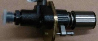
The design of modern diesel and gasoline power units may vary depending on the fuel system that the manufacturer uses in its cars. One of the most progressive developments of this system is the Common Rail fuel rail.
In short, its operating principle is as follows: a high-pressure fuel pump (read about its design here ) supplies diesel fuel to the rack line. In this element, the portion is distributed among the nozzles. Details about the operation of the system have already been described in a separate review , but the process is regulated by the ECU and the fuel pressure regulator.
Today we’ll talk in more detail about this part, as well as its diagnostics and operating principle.
Functions of the fuel pressure regulator
The function of the RTD is to maintain optimal fuel pressure in the engine injectors. This element, regardless of the intensity of the load on the unit, maintains the required pressure.
When engine speed increases or decreases, the amount of fuel consumed can either increase or decrease. To prevent a lean mixture from forming at high speeds and a too rich mixture at low speeds, the system is equipped with a vacuum regulator.
Another benefit of the regulator is compensation of excess pressure in the rack. If the vehicle were not equipped with this part, the following would happen. When less than the required amount of air enters through the intake manifold, but the pressure remains the same, the control unit would simply change the time of spraying the fuel (or the finished VTS).
However, in this case it is not possible to completely compensate for the excessive pressure. Excess fuel still has to go somewhere. In a gasoline engine, excess gasoline will flood the spark plugs. In other cases, the mixture will not burn completely, causing particles of unburned fuel to be removed into the exhaust system. This significantly increases the “gluttony” of the unit and reduces the environmental friendliness of automobile exhaust. The consequences of this can be very different - from heavy soot while driving to breakdown of the catalyst or particulate filter.
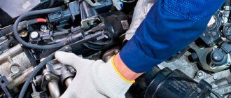
Checking the technical condition of the regulator
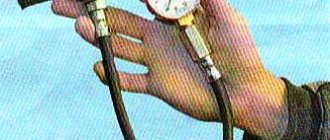
On models equipped with a standard pressure gauge, it is enough to simply read the readings of the device and compare them with standard data. For simpler models, you will need to connect an external pressure gauge to the system. In this case, the following sequence of work is performed:
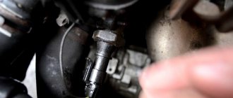
- Unscrewing the spool from the inner surface of the fitting.
- Attaching the pressure gauge hose to the fitting.
- Starting the internal combustion engine and reading the instrument readings.
- Removing the vacuum hose from the pressure regulator.
- Repeated readings at short intervals.
An increase in pressure by 20...80 kPa during repeated measurements will indicate the serviceability of the regulator. If the readings remain the same, the part should be considered faulty.
Operating principle of the fuel pressure regulator
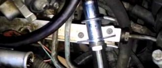
The fuel pressure regulator operates according to the following principle. The injection pump creates pressure, the fuel flows through the line into the ramp in which the regulator is located (depending on the type of vehicle).
When the volume of pumped fuel exceeds its consumption, the pressure in the system increases. If it is not reset, sooner or later the circuit will break at its weakest link. To prevent such a breakdown, a regulator is installed in the rail (it can also be located in the gas tank), which reacts to excessive pressure and opens an outlet to the return circuit.
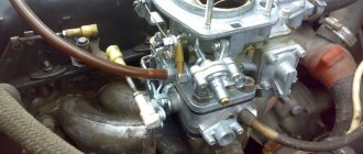
Fuel leaks into the fuel system hose and flows back into the tank. In addition to relieving excess pressure, the RTD reacts to the vacuum that is created in the intake manifold. The higher this indicator is, the less pressure the regulator will withstand.
This function is necessary so that the engine consumes less fuel while operating at minimum load. But as soon as the throttle valve opens further, the vacuum decreases, causing the spring to become stiffer and the pressure to increase.
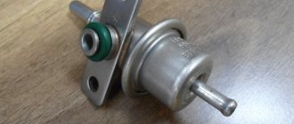
Device
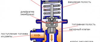
The design of classic regulators consists of the following parts:
- Durable metal housing (must have perfect tightness, as it is subject to changes in fuel pressure);
- The interior of the body is divided into two cavities by a diaphragm;
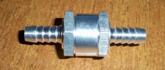
- To ensure that the fuel pumped into the ramp is retained there, a check valve is installed in the housing;
- A rigid spring is installed under the diaphragm (in the part where there is no fuel). This element is selected by the manufacturer in accordance with the modification of the fuel system;
- There are three fittings on the body: two for connecting the supply (input to the regulator and output to the injectors), and the other for return;
- Sealing elements for sealing the high pressure fuel system.
