Print this article Font size 16
On a VAZ 2110 car, the brake system has a hydraulic dual-circuit drive. It’s no secret that you can’t go far in a car without brakes and safety in this case is close to zero.
Today we will talk to you about how the brake system works on the domestic VAZ 2110 car, or, more simply, the “ten”, we will analyze its main malfunctions, as well as ways to eliminate potential and existing problems.
Principle of operation
Hydraulic dual-circuit brakes with diagonal distribution are predominantly efficient and reliable. This is due to the fact that if one circuit fails, the second will allow your car to brake.
The circuit system is arranged as follows - one of them is responsible for the left rear and right front wheel, and the second circuit is responsible for the left front and right rear wheel.
This way, you will be able to brake without damaging the brakes or causing other problems with the system.
Checking the brakes
After bleeding the master cylinder as well as the wheel cylinders, you need to check the functionality of the brakes before you go on a trip. So:
- The first is the pedal. She must take it high. Pump the pedal a few times, then press and check if the pedal falls off when pressed for a long time. If it falls, we pump the brakes again or look for another reason (we diagnose the brake system).
- Before leaving the garage, press the pedal several times.
- Select a suitable, spacious area to test the brakes.
- Accelerate the car a little (first gear will be enough).
- Let go of the steering wheel and apply the brakes. If the brakes work correctly, then all wheels will brake (visible from the marks of braking) and the car will not pull to the side.
- If it pulls away, it means that one wheel is working weaker. The reason for this may be the presence of air in the brake circuit of the wheel or a malfunction of the brake elements (working cylinder, piston or pads).
Watch the video which clearly shows how to bleed your brakes. Take care of the condition of your car, and it will serve you for a long time and safely!
Braking system design
The most important component of the VAZ 2110 brake system circuit is a vacuum booster and a dual-circuit regulator. The latter is responsible for creating pressure in the rear brake devices.
The brake drive is equipped with a piping system, which is divided into two circuits, brake devices and hoses. They allow the front and rear wheels to brake.
To activate the braking system, a special pedal is located inside the passenger compartment at the driver’s feet. In the VAZ 2110 car it is located in the middle.
The main elements of the hydraulic drive are:
- Vacuum booster. Its design helps create pressure directed towards the master cylinder piston. This creates a braking effect.
- Pressure regulator drive. Through it, the brake fluid is directed to the rear devices of the braking system.
- Directly the brake pressure regulator of the VAZ 2110. Its function is to be responsible for the pressure force. The unit reduces or increases this indicator, depending on the load on the rear axle of the car.
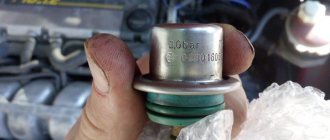
- Master cylinder with reservoir and pistons. On the filler neck of this tank there is a sensor that monitors the emergency level of brake fluid.
- Front wheel brake mechanism. Its design includes cylinders, pads and a disc, plus a special alarm that warns of wear or malfunction of the lining.
- Rear wheel brake mechanism. Here the system is not disk, but drum. At least, this is the design the factory envisages. Some VAZ 2110 owners believe that drum mechanisms are not reliable and efficient enough, and therefore install disk devices in their place.
System malfunctions
There are quite a lot of elements in the system, so it can be very difficult to determine the malfunction. The main malfunctions and their symptoms are described below:
- Braking is too slow.
A common problem that can be caused by grease or brake fluid getting into the friction area of the brakes. Also, a decrease in efficiency occurs due to wear or damage to the pads (only replacement will help). If the adjustment is made incorrectly, the system will overheat, and as a result, braking efficiency will noticeably decrease. Dismantling the amplifier - Increasing pedal stroke. Usually, with such a defect, the braking force decreases significantly, but sometimes it remains at the same level. The most common reason is a leak. First of all, you need to inspect the drums and calipers. If a damaged part is found through which the liquid escapes, it must be replaced. Air in the system hydraulic line can also cause an increase in stroke - to eliminate the problem, the brakes need to be properly bled (the process is described in detail below).
- After braking is completed, the “ten” wheels are partially released. The cause of the defect may be a violation of the protrusion of the adjusting nut on the vacuum booster rod. This malfunction can also be caused by jamming of one of the parts of the brake mechanism.
Why do you need a pressure regulator?
Not every owner of a domestic “ten” will understand why the brake pressure regulator on a VAZ 2110 needs to be replaced. Simply, this name is not familiar to everyone. A popular designation for a regulator is a sorcerer.
This very sorcerer is located on the rear suspension of your car. It has a lever with a movable position. Depending on the moment of load on the spring, its position changes.
The voltage generated during actuation is directed and distributed to the brake piston. Pressing the piston pedal reduces the load on the rear pads. If the brake system is working properly, the loads are distributed evenly.
In order for the unit to function efficiently and without errors, it is necessary to adjust the brake pressure regulator on your VAZ 2110. This way you can prevent untimely wheel locking.
Leveling up
So, we come to the main question - how to properly bleed the brakes on a VAZ 2110. But the important point here is whether you are going to do the work yourself, or call a friend for help. Depending on this, pumping is performed in a slightly different way. Let's talk about each of them.
Self-leveling
If you couldn’t find an assistant, you can easily handle the task yourself.
Container with TJ
To get started, arm yourself with:
- Brake reservoir cap without sensors, regular black;
- Automotive nipple;
- Use a round file or a 14 mm drill.
- Make a hole in the lid, insert a nipple into it so that there are no gaps and the element fits tightly. This device replaces a ready-made aerator, which is sold in stores.
- Using the manufactured device, connect the valve of the spare tire or removed wheel with the valve of the reservoir.
- Jack up the car and remove all wheels.
- Unscrew the fitting intended for bleeding the brakes. The air will expel the brake fluid with air bubbles.
- If it is not possible to use a tire or you have a compressor, use it. Just make sure the pressure is no more than 1 atmosphere.
- Perform a similar sequence of procedures on each brake, following the sequence indicated above.
https://youtube.com/watch?v=jkYHTz9lNgM
With an assistant
If you still managed to find a partner to work with, that’s good. This way, pumping the brakes is not only more convenient, but also more fun. Plus, the quality of the operation is often higher.
Top up
The sequence of your actions in this case will be as follows.
- Check the car for brake fluid leaks.
- Add TJ into the tank to the maximum level. It is designated as MAX.
- Hang up the wheel on which you plan to bleed the brakes. You already know the sequence.
- The rear brakes have a pressure regulator that can be locked with a screwdriver. It is inserted between the plate and the piston.
- The brake device has an air release valve. Dry it thoroughly, remove the cap and place the rubber hose on the head.
- Prepare a transparent container with a volume of about 3 liters in advance and pour into it some of the brake fluid used in your car. The other end of the hose must be immersed in this brake fluid.
- Command your assistant to sharply press the brake pedal about 5 times in a row. During the last press, the pedal is held in the down position.
- While he holds the pedal, you open the valve about 50-75 percent and watch the brake fluid flow out through the hose.
- Initially, liquid with bubbles should come out. As soon as the leak stops, the valve closes.
- Is the valve closed? Then tell your friend to release the pedal.
- But this is not how the brakes on a VAZ 2110 are pumped in just one step. For a high-quality procedure, you will have to repeat it 3 more times. You need to achieve a result in which no air bubbles come out of the hose.
- Carry out a similar procedure with all brake mechanisms in the specified bleeding sequence. Don't forget to remove the screwdriver that is blocking the pressure regulator.
As you can see, bleeding the brake system is not as difficult as it might seem at first glance. The easiest way is to work together, since then the process is much easier and does not require the creation of any special devices.
The main thing in this matter is not to rush. Consistent operation, careful actions in a strict sequence of brakes. Doing all this yourself is not a problem if you competently tackle bleeding the brake system of your car.
Loading …
Improvement of the braking system
Many VAZ 2110 owners agree that the factory brake system is far from perfect. Therefore, they decide to modernize and improve the unit using technical tuning.
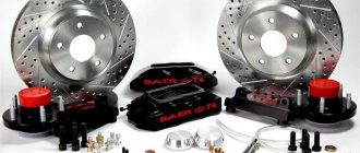
A popular solution to the issue of brake efficiency is to replace drum mechanisms with disc ones. Of course, in the case of the “ten” we are talking about the rear wheels. When replacing brakes, be sure to take into account the fact that the rear wheels must brake more softly and somewhat later than the front wheels. This way the car won't skid and you won't fly off the road.
Another option is to remove the factory brake master cylinder and vacuum booster. Instead, units from Priora are excellent. Such tuning will eliminate vibrations and also allow you to use the brake pedal effectively and without excessive effort.
Regardless of the changes made to the brake system, after each modification it is mandatory to pump the brakes.
Brake system for VAZ 2110 - design, repair
If the brakes are faulty, driving a car is strictly prohibited, so it is important to monitor the condition of the brake system. The brake system needs to be monitored and repaired in a timely manner, and repairing the brake system on a VAZ 2110 is not lengthy and labor-intensive, but if you lack the skills and tools, it is better to contact specialists.
In order to know for sure whether the technical condition of the most important function of the car is in order, you need to understand how the brake system on the VAZ 2110 is designed. What sore spots do all the well-known “ten” have and how to solve possible or already pressing problems yourself.
Problems and their solutions
There are several common problems associated with brakes on a VAZ 2110 car. The reasons for their occurrence may be different, but the solution is always the same - timely and high-quality repairs.
- The brakes have completely lost their effectiveness, pressing the pedal does not cause any reaction. In such a situation, it is categorically impossible to drive anywhere under your own power, even if we are talking about a trip to a service station? How do you brake? About a wall or pillar? Call a tow truck and start repairs. In some situations, the problem can be solved on the spot, but these are temporary measures.
- During braking, strong vibrations are observed, most often in the steering column. At the same time, when you press the pedal, it is difficult to hold the steering wheel in your hands. There may be several reasons for this: If you have non-ventilated discs installed, similar situations may arise during rain or when braking through a puddle. Such devices do not like moisture, so to get rid of vibrations, replace the disks with ventilated ones;
- Another cause of vibrations is faulty drums. If there are dark spots on the working surface of the drums, the unit wears unevenly. Immediate repair or complete replacement of mechanisms is required;
- Be sure to check for signs of deformation on the front brake discs. They often cause vibrations.
- The vacuum booster air filter may be clogged, causing the brake pedal to feel stiff;
As you can see, the brake system of the VAZ 2110 car is far from perfect in its factory version, but it performs its functions effectively and reliably. All possible malfunctions can easily be fixed independently, but in some situations it is advisable to contact a professional service station.
GTZ malfunctions
The VAZ 2101 brake system has many parts that can fail due to wear, poor quality or untimely maintenance. The following characteristic symptoms of problems can be identified:
- slow stopping of the vehicle after pressing the brake pedal. One of the reasons is that the lip seals of the pistons have become unusable, which led to a loss of tightness;
- high pedal effort. This problem appears when the cuffs increase in size, for example, when installing a low-quality repair kit;
- The brake pedal has a short stroke. The working environment, i.e. the brake fluid, has nowhere to go due to the fact that the compensation hole is clogged. In addition, the canal may be blocked by swollen cuffs;
- The car only brakes when the pedal is pressed to the floor. This indicates a complete failure of the lip seals when the liquid goes into the tank and not into the system;
- Brake pads do not move away from the discs and drums, causing them to become hot while driving.
The reason lies in the jamming of one of the pistons or the formation of a blockage in the bypass hole. If the seal is lost, liquid begins to flow out of the cylinder
These symptoms may also occur if there are problems with other parts of the braking system. For example, the pedal may fail if there is no fluid in one of the wheel cylinders or if air gets into the system
Therefore, for a final diagnosis, it is necessary to pay attention to additional features of the car’s behavior. For example, there are certain signs that clearly indicate problems with other components of the brake system, and not with the GTZ:
- pulling the car to the side when braking;
- jamming of the brake mechanisms on one of the wheels;
- the appearance of sounds uncharacteristic of normal brake operation (creaking, squeaking, grinding);
- heating of brake pads or discs on one wheel.
Checking the brake master cylinder
The most common cause of GTZ problems is wear of the seals. When replacing cuffs, you need to take into account that repairs only make sense if the piston and cylinder walls do not have wear. Otherwise, replacing the rubber seals will not bring any results and soon you will still have to install a new part. Before you start checking the main hydraulic brake drive, you should make sure that there are no problems with other elements of the system:
- Inspect the wheels from the inner surface to identify any leaks of brake fluid from the brake fluid brake system.
- Check the integrity of the tank and hoses connecting it to the gas turbine engine, as well as the presence of fluid and its level.
Fluid leaks on the inside of the wheel indicate a leak in the brake system.
A clear sign that there is a problem with the master cylinder is the appearance of liquid on the unit body. A working mechanism should always be dry without a hint of leakage. If the hydraulic drive has lost its seal, it must be dismantled for further disassembly and repair. You can determine that the gas turbine engine bypasses fluid, i.e., it does not enter the system, but returns to the expansion tank when you press the pedal:
- Open the tank lid.
- An assistant is seated in the driver's seat. The engine does not start.
- Your partner presses the brake pedal, and you listen to the sounds coming from the reservoir.
- If gurgling is heard from the container, and the pedal is pressed lightly, it means that the liquid is entering the tank instead of the system. The malfunction lies in the wear of the seals, which are unable to create the necessary pressure in the cylinder circuits.
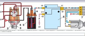
Hydraulic brake circuit diagram
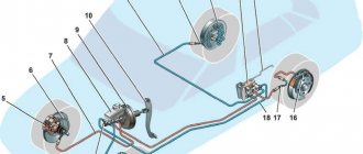
1 – front wheel brake mechanism; 2 – pipeline of the “left front–right rear brake” circuit; 3 – main cylinder for hydraulic brakes; 4 – pipeline of the “right front–left rear brake” circuit; 5 – master cylinder reservoir; 6 – vacuum booster; 7 – rear wheel brake mechanism; 8 – elastic lever of the pressure regulator drive; 9 – pressure regulator; 10 – pressure regulator drive lever; 11 – brake pedal; A – flexible hose of the front brake; B – flexible rear brake hose
The car uses a working brake system with diagonally separated circuits, which ensures high active safety of the car. One hydraulic drive circuit ensures the operation of the right front and left rear brake mechanisms, the other - the left front and right rear.
If one of the circuits of the service brake system fails, the second circuit is used to stop the vehicle with sufficient efficiency.
The hydraulic drive includes a vacuum booster 6 and a dual-circuit pressure regulator 9 for the rear brakes.
The parking brake system is driven by the brake mechanisms of the rear wheels.
2110 brake design
A dual-circuit hydraulic system with a vacuum brake booster is not uncommon on cars developed in the 80s. Easy to maintain, without unnecessary electronic bells and whistles, like ABS, cheap spare parts and pads. The front brakes are disc, and on models 2112, in the hatchback body, they are also ventilated with a larger diameter. This is because on the twelfth only 16-valve engines were installed and more effective brakes were needed to stop this incredible hundred-horsepower power. And also in order to cope with the Opel engine of 150 horsepower, which was also sometimes used for modification by dozens.
The rear brakes are tens of drum type, and the parking brake is mechanical. Everything is like in the good old classics. The car has a vacuum brake booster and the system is divided into two circuits. If one of them fails, the second one remains operational, so there won’t be a dozen left without brakes. The circuits work in a diagonal pattern - front-rear wheel diagonally. Also, the brake system of the VAZ 2110, the diagram of which is presented above, has a pressure regulator for uniform distribution of braking force, depending on the load of the rear axle. Both brake circuits are connected through the regulator.
Vacuum booster
1 – vacuum booster housing;
2 – amplifier housing cup; 3 – rod; 4 – adjusting bolt; 5 – rod seal; 6 – sealing ring of the master cylinder flange; 7 – diaphragm return spring; 8 – amplifier pin; 9 – tip mounting flange; 10 – valve; 11 – hose tip; 12 – diaphragm; 13 – amplifier housing cover; 14 – sealing cover; 15 – piston; 16 – protective cover of the valve body; 17 – air filter; 18 – pusher; 19 – pusher return spring; 20 – valve spring; 21 – valve; 22 – valve body bushing; 23 – rod buffer; 24 – valve body; A – vacuum chamber; B – atmospheric chamber; C, D – channels The rubber diaphragm 12 together with the valve body 24 divides the cavity of the vacuum amplifier into two chambers: vacuum A and atmospheric B. Chamber A is connected to the engine inlet pipe through the check valve of the tip 11 and a hose.
The 24 valve body is plastic. At the exit from the cover, it is sealed with a corrugated protective cover 16. The valve body contains the main cylinder drive rod 3 with a support sleeve, rod buffer 23, valve body piston 15, valve assembly 21, pusher and valve return springs 19 and 20, air filter 17 , pusher 18.
When you press the pedal, the pusher 18, the piston 15, and after them the valve 21 move until it stops against the seat of the valve body. In this case, cameras A and B are separated. As the piston moves further, its seat moves away from the valve and through the resulting gap, chamber B is connected to the atmosphere. The air entering through filter 17, the gap between the piston and the valve and channel D creates pressure on the diaphragm 12. Due to the difference in pressure in chambers A and B, the valve body moves along with the rod 3, which acts on the piston of the main cylinder.
When the pedal is released, valve 21 moves away from the body seat and through the resulting gap and channel C of chambers A and B communicate with each other.
Pressure regulator drive
1 – pressure regulator; 2, 16 – pressure regulator mounting bolts; 3 – bracket for the pressure regulator drive lever; 4 – pin; 5 – pressure regulator drive lever; 6 – axis of the pressure regulator drive lever; 7 – lever spring; 8 – body bracket; 9 – pressure regulator mounting bracket; 10 – elastic lever of the pressure regulator drive; 11 – earring; 12 – earring bracket; 13 – washer; 14 – retaining ring; 15 – bracket pin; A, B, C – holes
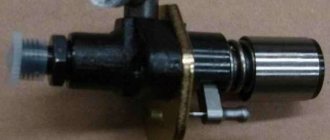
Pressure regulator
1 – pressure regulator housing;
2 – piston; 3 – protective cap; 4, 8 – retaining rings; 5 – piston sleeve; 6 – piston spring; 7 – body bushing; 9, 22 – support washers; 10 – sealing rings of the pusher; 11 – support plate; 12 – pusher bushing spring; 13 – valve seat sealing ring; 14 – valve seat; 15 – sealing gasket; 16 – plug; 17 – valve spring; 18 – valve; 19 – pusher bushing; 20 – pusher; 21 – piston head seal; 23 – piston rod seal; 24 – plug; A, D – chambers connected to the main cylinder; B, C – chambers connected to the wheel cylinders of the rear brakes; K, M, N – clearances The pressure regulator regulates the pressure in the hydraulic drive of the brake mechanisms of the rear wheels depending on the load on the rear axle of the car. It is included in both circuits of the brake system and through it brake fluid flows to both rear brake mechanisms.
Pressure regulator 1 (Fig. Pressure regulator drive) is attached to bracket 9 with two bolts 2 and 16. At the same time, front bolt 2 simultaneously secures fork bracket 3 of lever 5 of the pressure regulator drive. A double-arm lever 5 is hinged on the pin of this bracket with a pin 4. Its upper arm is connected to an elastic lever 10, the other end of which is pivotally connected to the rear suspension arm bracket through an earring 11.
Bracket 3 together with lever 5 can be moved relative to the pressure regulator due to the oval holes for the fastening bolt. This regulates the force with which lever 5 acts on the regulator piston (see subsection 6.4.2). The regulator has four chambers: A and D (Fig. Pressure regulator) are connected to the main cylinder, B to the left, and C to the right wheel cylinders of the rear brakes.
In the initial position of the brake pedal, piston 2 (see Fig. Pressure regulator) is pressed by lever 5 (see Fig. Pressure regulator drive) through leaf spring 7 to pusher 20 (see Fig. Pressure regulator), which is pressed against the saddle under this force 14 of valve 18. In this case, valve 18 is pressed away from the seat and a gap H is formed, as well as a gap K between the piston head and seal 21. Through these gaps, chambers A and D communicate with chambers B and C.
When you press the brake pedal, fluid flows through gaps K and H and chambers B and C into the wheel cylinders of the brake mechanisms. As the fluid pressure increases, the force on the piston increases, tending to push it out of the housing. When the force from the liquid pressure exceeds the force from the elastic lever, the piston begins to move out of the body, and after it, under the action of springs 12 and 17, the pusher 20 moves together with the sleeve 19 and rings 10. In this case, the gap M increases, and the gaps H and K decrease . When the gap H is completely selected and the valve 18 isolates chamber D from chamber C, the pusher 20, together with the parts located on it, stops moving after the piston. Now the pressure in chamber C will vary depending on the pressure in chamber B. With a further increase in the force on the brake pedal, the pressure in chambers D, B and A increases, piston 2 continues to move out of the body, and sleeve 19 together with o-rings 10 and plate 11 under increasing pressure in chamber B, it shifts towards plug 16. At the same time, the gap M begins to decrease. Due to the decrease in the volume of chamber C, the pressure in it, and therefore in the brake drive, increases and will be practically equal to the pressure in chamber B. When the gap K becomes zero, the pressure in chamber B, and therefore in chamber C, will increase less degree than the pressure in chamber A due to throttling of the liquid between the piston head and seal 21. The relationship between the pressure in chambers B and A is determined by the ratio of the difference in the areas of the head and piston rod to the area of the head.
As the vehicle load increases, the elastic lever 10 (see Fig. Pressure regulator drive) is loaded more and the force from lever 5 on the piston increases, that is, the moment of contact between the piston head and seal 21 (see Fig. Pressure regulator) is achieved at greater pressure in the main brake cylinder. Thus, the effectiveness of the rear brakes increases with increasing load.
If the brake circuit “left front – right rear brake” fails, the o-rings 10, bushing 19, under the fluid pressure in chamber B, will move towards the plug 16 until the plate 11 rests on the seat 14. The pressure in the rear brake will be regulated by part of the regulator, which includes piston 2 with seal 21 and bushing 7. The operation of this part of the regulator, in the event of a failure of the said circuit, is similar to the operation with a working system. The nature of the change in pressure at the outlet of the regulator is the same as with a working system.
If the brake circuit “right front – left rear brake” fails, the pressure of the brake fluid forces the pusher 20 with the bushing 19 and sealing rings 10 toward the piston, pushing it out of the housing. The M gap increases and the H gap decreases. When valve 18 touches seat 14, the increase in pressure in chamber C stops, that is, the regulator in this case works as a pressure limiter. However, the achieved pressure is sufficient for reliable operation of the rear brake.
There is a hole in housing 1, closed by plug 24. Liquid leakage from under the plug when it is squeezed out indicates a leak in rings 10.
Leveling: detailed instructions
Bleeding is required to remove all air from the system.
In this work, it is important to remember that the circuit diagram is diagonal, so you need to bleed it as follows: first the rear wheel goes on the right side, then the front wheel on the left. In general, the work is done “diagonally”
To bleed, you will need a standard set of tools and materials: a jack, brake fluid, a set of wrenches and sockets, as well as screwdrivers.
First, consider working with a friend:
- The first step is to fill the reservoir with brake fluid to the “max” mark;
- Next you need to hang the rear wheelset. A screwdriver must be placed between the piston and the plate, thus blocking the brake mechanisms. The main thing is not to forget to take out the screwdriver after completing the work;
Now you need to insert a screwdriver between the plate and the piston
The cap must be removed from the air release valve. A clean hose must be placed on the valve head, the other end of which must be in a transparent container filled with brake fluid;
Place the hose in a container to drain the liquid
After this, the partner must press the corresponding pedal several times (the intervals between presses should be 1-2 seconds). When pressing the last time, the pedal must be pressed to the bottom and not released; The next step is to adjust the valve - it needs to be unscrewed 0.5-0.75 turns, after which liquid will begin to drip, along with it air bubbles will come out of the system. When everything comes out, the valve must be closed, while the partner must remove his foot from the pedal; Next, check the fluid level; if everything is in order, then reassemble in the reverse order.
To do the work yourself, you need to purchase a unit called “AERATOR”. Some people make the device with their own hands, but it is better to buy a ready-made unit for 70 rubles. Pumping is carried out as follows:
- The valve on the tank must be combined with the wheel valve using a new tool;
- The VAZ 2110 should be jacked up and the wheels should be hung;
- The bleeder fitting should be removed; the brake fluid will flow away due to the created compression;
- To do this, enough air from one tire.
Advice! Some motorists struggle with the air supply. The easiest way to do this work is with a pump that inflates tires. If there is a compressor in the garage, then it is better to use it.
Master cylinder with reservoir
1 – main cylinder body;
2 – low pressure sealing ring; 3 – drive piston of the “left front–right rear brake” circuit; 4 – spacer ring; 5 – high pressure sealing ring; 6 – pressure spring of the sealing ring; 7 – spring plate; 8 – piston return spring; 9 – washer; 10 – locking screw; 11 – drive piston of the “right front–left rear brake” circuit; 12 – connecting sleeve; 13 – tank; 14 – brake fluid emergency level sensor; A – clearance Master cylinder with sequential arrangement of pistons. A tank 13 is mounted on the master cylinder body, in the filler neck of which a sensor 14 for emergency brake fluid level is installed. The high pressure O-rings 5 and the rear wheel cylinder rings are interchangeable.
Front wheel brake
1 – brake disc;
2 – pad guide; 3 – caliper; 4 – brake pads; 5 – cylinder; 6 – piston; 7 – pad wear indicator; 8 – sealing ring; 9 – protective cover of the guide pin; 10 – guide pin; 11 – protective casing The front wheel brake mechanism is disc, with automatic adjustment of the gap between the pads and the disc, with a floating caliper and a brake pad wear indicator. The bracket is formed by a caliper 3 and a wheel cylinder 5, which are tightened with bolts. The movable bracket is bolted to pins 10, which are installed in the holes of the guide 2 of the pads. Lubricant is placed in these holes, rubber covers 9 are installed between the pins and the pad guide. Brake pads 4 are pressed against the grooves of the guide by springs, the inner one of which has a lining wear indicator 7.
A piston 6 with a sealing ring 8 is installed in the cavity of the cylinder 5. Due to the elasticity of this ring, the optimal gap between the pads and the disk is maintained.
Description of design
Diagram of the hydraulic brake drive
1 – main cylinder of the hydraulic brake drive 2 – pipeline of the “right front – left rear brake” circuit 3 – flexible hose of the front brake 4 – master cylinder reservoir 5 – vacuum booster 6 – pipeline of the “left front – right rear brake” circuit 7 – rear wheel brake
8 – elastic pressure regulator drive lever 9 – flexible rear brake hose 10 – pressure regulator 11 – pressure regulator drive lever 12 – brake pedal 13 – front wheel brake mechanism
The service brake system is hydraulic, dual-circuit (with diagonally separated circuits), with a pressure regulator 10, a vacuum booster 5 and an indicator of insufficient brake fluid level in the reservoir. If one of the brake system circuits fails, the second circuit provides braking of the vehicle, although with less efficiency.
The brake mechanisms of the front wheels 13 are disc (on VAZ-21103, -21113 and -2112 vehicles - ventilated), with a single-piston floating caliper and a brake lining wear indicator. The brake mechanisms of the rear wheels 7 are drums, with two-piston wheel cylinders and automatic adjustment of the gap between the shoes and the drum. The automatic clearance adjustment device is located in the wheel cylinder.
The main brake cylinder 1 is attached to the housing of the vacuum booster 5 on two studs. A translucent polyethylene tank 4 with an emergency liquid level sensor is inserted into the holes in the upper part of the cylinder on rubber seals. The tank has markings for maximum and minimum fluid levels. Two screws are screwed into the bottom of the cylinder to limit the movement of the pistons. The screws are sealed with copper gaskets. In the front part of the cylinder (along the direction of the car) there is a plug screwed in that serves as a stop for the return spring, also sealed with a copper gasket. The pistons in the master cylinder are arranged in series, the one closest to the vacuum booster operates the right front and left rear brake mechanisms, and the one closest to the plug operates the left front and right rear. The high-pressure rubber sealing rings (cuffs) of the master brake cylinder and rear wheel cylinders are interchangeable (nominal diameter - 20.64 mm). The low pressure sealing ring is grooved, installed on the piston in contact with the vacuum booster rod.
Vacuum booster 5 is located between the pedal assembly and the main brake cylinder 1 and is attached to the pedal assembly bracket with two studs. The amplifier is of a non-separable design; if it fails, it should be replaced. The simplest way to check the serviceability of the amplifier: on a car with the engine turned off, press the brake pedal several times and, holding the pedal down, start the engine. If the amplifier is working properly, when the engine starts running, the pedal should move forward. Failure to operate or insufficient efficiency of the vacuum booster can also be caused by a leak in the hose that takes vacuum from the intake manifold.
The rear brake pressure regulator 10 is attached with two bolts to a bracket in the left rear part of the body. One of these bolts (front) also secures the fork bracket of the pressure regulator drive lever 11. Due to the ovality of the holes for its fastening, the bracket together with the lever can be moved relative to the pressure regulator, changing the force with which the lever acts on the regulator piston (see Checking and adjustment rear brake pressure regulator drive). As the load on the rear axle of the vehicle increases, the elastic lever is also loaded, transmitting force to the pressure regulator piston. When you press the brake pedal, the fluid pressure tends to push the piston outward, which is prevented by the force from the elastic lever. When the system comes into balance, a valve located in the regulator isolates the rear brake cylinders from the master cylinder, preventing further increases in braking force on the rear axle and preventing the rear wheels from locking up ahead of the front wheels. As the load on the rear axle increases, when the traction of the rear wheels with the road improves, the regulator provides more pressure in the wheel cylinders and vice versa - as the load decreases, the pressure drops. There is a hole in the regulator body that is closed with a plug. Leakage of brake fluid from this hole indicates leakage of the regulator O-rings.
The floating front brake caliper includes a caliper and a wheel cylinder, which are held together by two bolts. The other two bolts secure the bracket to the pins installed in the holes in the pad guide. Lubricant is placed in these holes. Rubber protective covers are installed between the pins and the pad guide. The brake pads are pressed against the guide grooves by springs. The inner pad has a lining wear indicator. The cylinder contains a piston with a rectangular rubber sealing ring. Due to the elasticity of this ring, a constant optimal gap between the brake pads and the disc is maintained.
Brake discs are cast iron. The minimum permissible disc thickness during wear is 17.8 mm for ventilated discs and 10.8 mm for non-ventilated discs, the maximum runout along the outer radius is 0.15 mm.
The rear wheel brake cylinders are equipped with a device to automatically maintain the gap between the shoes and the drum. The main element of the device is a steel spring split ring mounted on the piston with an axial clearance of 1.25-1.65 mm. The thrust rings (two per cylinder) are inserted with an interference fit, providing a shear force along the cylinder surface of at least 35 kgf, which exceeds the force of the brake pad tension springs. When the brake linings wear, the thrust rings shift under the action of the pistons by the amount of wear. If the piston mirror is damaged by mechanical impurities that have entered the brake fluid or formed due to corrosion (the presence of water in the brake fluid), the rings may “sour” in the cylinder and one or even both pistons will lose mobility. In this case, the cylinders must be replaced.
The parking brake system is driven mechanically, by cable, to the rear wheels. It consists of a lever, an adjusting rod, an equalizer for two cables, a pad drive lever and a spacer bar.
| « previous page 14.4. Removing the tie rod and ends | to contents | next page » 15.1. Description of design |
Copyright © 2007-2019 All rights reserved. All trademarks are property of their respective owners.
Wheel cylinder
1 – block stop;
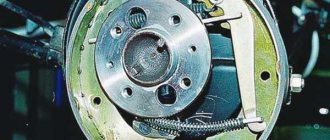
2 – protective cap; 3 – cylinder body; 4 – piston; 5 – seal; 6 – support plate; 7 – spring; 8 – crackers; 9 – thrust ring; 10 – thrust screw; 11 – fitting; A – slot on the thrust ring The brake mechanism of the rear wheel (Fig. Brake mechanism of the rear wheel) is drum, with automatic adjustment of the gap between the shoes and the drum. The automatic clearance adjustment device is located in the wheel cylinder. Its main element is a split thrust ring 9 (Fig. Wheel cylinder), installed on the piston 4 between the shoulder of the thrust screw 10 and two nuts 8 with a gap of 1.25–1.65 mm.
The thrust rings 9 are inserted into the cylinder with tension, providing a shear force of the ring along the cylinder mirror of at least 343 N (35 kgf), which exceeds the force on the piston from tension springs 3 and 7 (see Fig. Brake mechanism of the rear wheel) of the brake pads.
When, due to wear of the linings, the gap of 1.25–1.65 mm is completely removed, the shoulder on the thrust screw 10 (see Fig. Wheel cylinder) is pressed against the shoulder of the ring 9, as a result of which the thrust ring moves after the piston by the amount of wear. When the braking stops, the pistons are moved by the force of the tension springs until the cracks stop against the shoulder of the thrust ring. This automatically maintains the optimal clearance between the pads and the drum.
When to bleed the brakes
This issue must be approached with full responsibility. First, let's look at the situations in which air can enter.
- The brakes must be bled after repairs have been made to the brake system. Note that after replacing the pads there is no need to bleed the system.
- When replacing a brake rubber tube, rear working and master brake cylinder, pipeline - these and some other types of work involve bleeding the brake system.
- When the VAZ-2112 runs out of “brake fluid” in the expansion tank, air also penetrates freely. The reason here is both a malfunction of the system and a violation of the integrity of the tank itself.
- Based on the position of the brake pedal, you can determine the need for bleeding. The pedal in its normal position is not pressed down immediately; first, when pressed, pressure is created in the system. Having reached approximately a quarter of the stroke, the pedal completely blocks all tires of the vehicle.
- If air gets into the system, the pedal will go idle for a small part of its travel, that is, it will fail.
- Quite often, the VAZ-2112 needs not only bleeding of the brakes, but also the subsequent dismantling of the brake system.
What tools and devices will be useful in your work:
- the brake fluid itself;
- container (half-liter bottle);
- wrench for 8 and 10 (ordinary open-end or special, looks like a regular one, but has a slot);
- tube (hose) for the fitting;
- lubricant for rust removal, for example, VD-40;
- metal brush.
Parking brake system drive
The mechanically actuated parking brake system acts on the brake mechanisms of the rear wheels. The parking brake drive consists of lever 2, adjusting rod 4, equalizer 5, cable 8, lever 10 (see Fig. Rear wheel brake mechanism), manual pad drive and expansion bar 8.
1 – protective cap; 2 – sensor housing; 3 – sensor base; 4 – sealing ring; 5 – clamping ring; 6 – reflector; 7 – pusher; 8 – bushing; 9 – float; 10 – fixed contacts; 11 – moving contact
Mechanical brake fluid emergency level sensor. The sensor body 2 with a seal 4 and the base 3 with a reflector 6 are pressed by a clamping ring 5 to the end of the tank neck.
A pusher 7 passes through the hole in the base, connected to the float 9 by means of a sleeve 8. There is a moving contact 11 on the pusher, and fixed contacts 10 are located on the sensor body. The contact cavity is sealed with a protective cap 1. When the level of brake fluid in the reservoir drops to the maximum permissible, the moveable the contact moves down onto the fixed contacts and closes the circuit of the hazard warning lamp on the instrument panel.
Let's get started
Only after a thorough inspection of the parts is the brakes properly pumped. The VAZ-2110 is placed on a flat platform. First, the rear right part is hung out and the wheel is removed. Next, check the fluid level in the plastic tank. It should be at an average level, but not below the minimum. So, add fluid to the MAX mark and start bleeding the brakes. First, clean the valve from dirt. Next, remove the protective rubber cap from it. A hose is placed over the valve head. Its second end is lowered into a clean transparent bottle (for example, a mineral water bottle).
Now we call a second person for help. He will press the pedal sharply 4-5 times at 2 second intervals. On the last “roll” you need to fix the pedal in the depressed position. How to bleed the brakes on a VAZ-2110 further? After this, you unscrew the air release valve and look at the condition of the fluid. It will have bubbles at first. After the liquid has left the valve under pressure, the assistant releases the pedal back.
Device
Hydraulic brakes are installed on the machine and operate generally reliably. They are double-circuit and have a diagonal distribution. That is, if one part suddenly fails, then braking by another circuit is possible. For the sake of safety, the VAZ 2110 brakes operate diagonally, one circuit is the right front and left rear wheels, the other is also diagonal.
This device allows you to brake efficiently (without skidding and other troubles) even in the event of a malfunction, if the brakes in one of the circuits are lost.
Let's consider the design of the brake system. The hydraulic drive includes a vacuum booster, as well as a dual-circuit regulator that creates pressure in the rear brakes.
In addition, the hydraulic drive is equipped with pipelines divided into two circuits, hoses and brake mechanisms that provide braking to the front and rear mechanisms.
The hydraulic drive is activated by a pedal located in the cabin (middle). Here are the main components of the hydraulic drive:
- Vacuum booster.
It is designed in such a way that it creates pressure on the master cylinder piston, and thus causes braking; Vacuum brake booster - Pressure regulator drive.
It is through it that the working brake fluid flows to the rear brake mechanisms; Brake pressure regulator drive - The pressure regulator itself.
Already from the name it is clear that this device is responsible for the force of pressure, its decrease or increase. He does this depending on how loaded the rear axle of the car is; Pressure regulator - Main cylinder with pistons, equipped with a reservoir.
The filler neck of the tank is equipped with an emergency fuel level sensor; Master brake cylinder - Brake mechanism for the front wheel.
Its main parts are the disc, pads and wheel cylinders. The mechanism also provides an indicator to prevent complete wear and malfunction of the linings; Front wheel brake - Brake mechanism for the rear wheel.
Unlike the front disc brakes, the rear ones are drum brakes. This is the factory configuration. However, many car owners believe that their device does not provide high-quality braking, and change them to disc ones. Rear wheel brake
The brakes require attention. Without waiting for the warning light to come on, indicating a critical level of fuel fluid or wear of the linings, and even more so, without allowing the brakes to completely disappear, you need to carry out preventive checks.
Particular attention should be paid to all connections and hoses, since the “escaped” brake fluid will not make it possible to brake, and from here it’s not far from tragedy.
Problem in the operation of the central locking electrical circuit on VAZ cars
The first possible problem follows smoothly from those mentioned in the previous section. Overload in the operation of activators leads to an increase in the operating current in the supply circuit above the rated value. As a result, the fuse blows and the central locking of the VAZ 2110 simply “dies”.
It is by checking the fuse that the diagnosis of central locking malfunctions begins. By the way, it is located in a very specific place and it is not easy to find it right away even if you know where to look. In order to get to it, you will need to fold back the central panel with the fuses and dig into the entire wiring harness in the niche that opens behind it. The “comrade” you need is packaged in a special plastic cup and connected to the pink wire.
Central locking unit VAZ 2110
Another very common and obvious problem is the central locking connector. It is located in the most unfavorable place for this in the interior body, under the foot mat. A large amount of moisture and dirt inevitably gets there. Electrical contacts are intensively oxidized. As a result, the power supply circuit involuntarily breaks at the point where the plug connector is connected.
Alarm Signals
The following symptoms are quite unsafe, please note:
- If the brakes are completely gone, then it’s clear that you can’t go any further, even to a service station! If independent repairs on site are beyond your capabilities, or simply impossible, you need to call a tow truck;
- When braking there is a strong vibration, especially felt in the steering column. You press the pedal, and it’s just hard to hold the steering wheel in your hands. There can be several reasons for vibration: • Many argue that vibration can occur due to the fact that there are non-ventilated disks. Their design is such that they really don’t like it when braking occurs in the rain, or even right in a puddle. No repair will help here - you need to replace the disks with ventilated ones; • Vibration may also occur if there is a problem with the rear drums. If upon inspection you find dark spots on the working surface, this indicates uneven wear. The vibration is usually very strong. Such drums need urgent repairs, and possibly replacement with disc brakes; • Check the front brake discs for deformation. At the same time, vibration is also observed.
- The brake pedal is too tight. There may also be several reasons for this: • A clogged air filter for the vacuum booster can cause the pedal to become stiff; • Check the vacuum booster itself. Its possible malfunctions are destruction of the diaphragm, tip, sticking of the check valve, damage to the hose connecting the intake manifold to the amplifier. In all these cases, a stiff pedal syndrome may occur, and repair of any of the indicated faults is necessary; • Also, the pedal may become stiffer as the pads wear, check them too.
- Hisses when you press the brake. If it hisses exactly when you press the pedal, you need to urgently check the vacuum booster, and then decide whether it needs repair or replacement. But if it hisses when you release the brake, then this is a normal phenomenon. Unless, of course, the hiss is too obvious.
Pumping the brakes
Now you can get started. On a VAZ 2112 we pump the brakes ourselves. The price at a service station for pumping is small, but you can save money, and by the time you get to the station, you can already have time to pump the brakes.
Master brake cylinder
After replacing the main brake or parts that are connected directly to it (pipes), it is necessary to bleed it. This is done differently than bleeding the brakes on wheels!
VAZ 2112 bleeding the brakes yourself
- After installing the new cylinder, fill the expansion tank of the VAZ 2112 brake system with brake fluid to the level. In general, fill the tank full.
- Then your partner should be seated behind the wheel, and you yourself should take a seat on the left side of the car to ensure maximum access to the master cylinder.
- All fittings that secure the brake pipes to the master cylinder must first be tightened.
- Now the procedure is as follows. The partner pumps up the pressure in the system with the pedal, then presses the brake pedal to the floor and holds it there.
Your partner presses and holds the pedal
- You should use a bleeder wrench or a regular 10 wrench to unscrew one of the fittings of the master brake cylinder.
- After unscrewing it, you will be able to observe how a small amount of brake fluid comes out from under the fitting along with air bubbles. So, there shouldn't be any bubbles.
- Tighten the fitting. After which the partner releases the pedal. And then he presses it again.
- At this time, you unscrew the SAME fitting and observe what is happening.
- This procedure must be performed until there is no air left.
- But that's not all. Next, you should do the same operation with each fitting.
There is another option for bleeding the main brake cylinder:
The essence of the process does not change. The steps are the same and the order is the same. In order to speed up the process, while your partner holds the pedal, you unscrew and tighten each fitting in turn
This is all done with ONE PRESS OF THE PEDAL, please note. But nevertheless, all the air will not come out with one press and the procedure will still have to be repeated.