Full locking of the doors guarantees the safety of the car, as well as the safety of the car owner’s personal belongings. Almost all modern vehicles are equipped with such a system. However, not every motorist understands the principle of operation of the device, and also knows about the components of the central locking system. That is why, here it is necessary to highlight the most important nuances of the mechanism, and in addition, talk about the elements of a centralized locking system, since under certain circumstances you have to deal with the repair and maintenance of components.
Central locking - what is it?
In this case, we are talking about a system that allows you to simultaneously lock all the doors of the car, including the trunk lid. It is noteworthy that without such a component, the car enthusiast can still close and open the doors. True, in this situation you will have to do everything manually, whereas with a central lock, unlocking occurs remotely. It is worth noting that the presence of this option does not in any way affect the technical characteristics of the car, which is why this system is classified as a comfort function.
It is noteworthy that this option can be controlled in two ways available to the motorist, namely:
- manually by turning the key;
- remotely using the appropriate key fob.
It is also worth noting that the central locking in the current version can be installed on the car in two versions - centralized and decentralized.
In the first case, we are talking about the standard unlocking of the doors and trunk lid using a key fob or turning the key in the driver's door cylinder. The second situation involves a more advanced system where an electronic control unit is present for each door, which makes it possible to program and unlock specific doors separately. With a centralized locking system, the control unit is single.
Types and types of actuators
The actuator is the actuator of the lock drive. Any such mechanism is enclosed in a plastic case, and an electric motor is installed inside it. The engine is equipped with two contacts, the wires from which are led out.
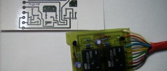
Door lock actuator (two wire)
The two power wires are sometimes supplemented by two or three signal cords, which are connected to microswitches. A module equipped with such options is usually implemented according to the following scheme:
Driver's door lock actuator
There may be 4-5 signal wires, but the point here is different: these cables will be shorted when the drive is moved to one of the fixed positions. And there are usually two of these positions: completely open, locked.
It is important to understand the logic of the microphone’s operation: until the rod is fully retracted, the toggle switch remains in the “open” position. And vice versa: the toggle switch will take a different position if the rod is pressed out to the end
It’s easier to imagine that the switching occurs after the rod stops. There is nothing more to add here.
Connection of a microphone built into the actuator is provided only in some signal models. And for all doors except the driver's, two-wire drives (without microswitches) are suitable.
Standard set for sedan
In any case, it is better to buy one 5-wire actuator. By the way, the resistance of each motor is 5 Ohms (calculate the total current). Happy shopping!
Main features of the central lock
Despite the fact that central locking is a fairly simple option, it has some features that should be considered without fail, as this will answer some popular questions from motorists, namely:
- the option may well work with any alarm system;
- You can independently connect the trunk lid to the system;
- the trunk will require separate controls;
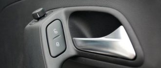
- To make it convenient for the driver, the central locking button is present on the key fob and in the cabin.
Also, do not forget that in severe frosts the central locking elements may freeze, in which case the car will have to be opened manually using the lock on the driver's door.
The fundamental difference between the main types of central locking
Fundamentally, devices for automatic unlocking/locking of door locks can be divided into 2 types:
- Central locking with electric drive. Electric activators are installed in the doors. Each mechanism can have an individual control unit or be controlled by a single unit (this is the scheme used on budget cars);
- pneumatic central locking. The activator rod moves due to changes in air pressure inside the line. At the moment, the system is outdated and not used; in the past, such systems were installed by Mercedes, BMW, VW, Audi. It is not economically feasible to restore such a system or install it yourself. It is much easier to install electrical activators by connecting everything to a unit with a remote control function.
We will consider central locking with electric drives. Devices of this type are divided into 2 types:
- with positive potential control;
- with negative potential control.
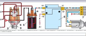
What a control signal is and why it is needed will become clear to you when we look at the operating principle of the simplest central locking system. As an example, let's take the most common scheme on budget cars with minus control. The schematic diagram is taken from the Opel Astra F repair and operation manual.
System components
Since central locking is, at its core, a fairly simple system, there are only a few main components. In particular, we are talking about the following elements:
- input sensors of the centralized system;
- electronic control unit;
- auxiliary actuator.
Of course, this system also includes a wiring kit that connects all components into a single network, allowing the driver not to make any effort to unlock all or individual car doors.
Input sensors
In this case, we are talking about limit switches - input sensors that allow you to transmit information, as well as the location of the doors at the current moment in time, and send information to the control unit, as well as microswitches. The latter determine the position of the mechanical components of the central locking at the moment of unlocking or locking during the activation process. It is noteworthy that two microswitches are responsible for fixing the cam mechanism. A separate switch in this case allows you to accurately determine the position of the lever mechanism in the lock drive. All this helps to accurately recognize in what position the doors are located in relation to the body at this moment.
Provided that the door is open, the system closes the contacts on the switches, after which the central locking function cannot operate. Next, the current information is transmitted directly to the control unit. It transmits everything needed to the actuators used to close the doors, as well as the trunk lid and the gas filler flap.
Electronic control unit
Like any other system, the central locking has its own control unit, which is responsible for the operation of the entire circuit. As soon as information from the input sensors arrives at the ECU, analysis occurs here, as well as subsequent distribution to the actuators. It is noteworthy that the electronic control unit also interacts with the alarm system. This in turn opens up the possibility of remote control of the system using an appropriate, programmed key fob.
Actuator
Another extremely important element of a centralized locking system or central locking system. In this case, we are talking about an actuator or the final link of the entire circuit, which in turn is directly responsible for blocking the doors. It is noteworthy that the actuator itself is a conventional electric motor operating on the basis of direct current. The device is combined with a simple gearbox and converts the action of a rotating electric motor into reciprocating movements of the lock cylinder. It is noteworthy that in addition to electric motors, some vehicles are equipped with a pneumatic drive. A striking example is the automobile brands Volkswagen and Mercedes-Benz. It is worth recalling that these devices were used previously, but have been abandoned in recent years.
Connection of the “signaling” depending on the type of central locking
Depending on the type of lock product, the installation and connection of the security system will proceed differently. Before performing the connection procedure, you need to find the signal circuits.
To do this, you need to understand the types of control modules for central locking:
- Block with negative polarity. When you close one of the signal contacts to ground, the locking devices will automatically close. They are opened by closing the second contact to ground.
- The module is controlled via positive polarity. In this case, the procedure for opening and closing doors is similar. Only +12 volts is supplied to each of the contacts.
- The module can work with an alternating signal. One output of the device is connected to the ground to the body, and the other receives 12 volt voltage. This leads to the unlocking of the locking devices. When the polarity changes, the devices are closed. If voltage is supplied to the contacts separately, this will not affect the functioning of the devices in any way.
For the first case, you can find a way out using a control light. The light indicator is connected to the ground of the car, that is, its body, after which each output is diagnosed separately. If it is necessary to find a positive output, then the test lamp is connected to the positive contact.
Central locking with negative polarity
Scheme for connecting central locking with negative potential
The outputs of the security system used for central locking are divided into power and signal. If we are talking about a device with negative polarity, then relays will be used for connection. This refers to elements with which you can unlock and close lock products.
You can connect the alarm to the central locking in accordance with the diagram below:
- The green contact is connected to the connector of the security complex. It is used to close door locks.
- The white output also goes to the “signaling” block, intended for opening locks.
In accordance with the diagram, the upper node of the system is made in the form of a closing relay. Open contact components are connected to ground, the car body. And the general outputs must be connected to the signal contacts of the locking device. Please note that there is no need to cut the cables from the processor module plug; you need to connect the outputs to them, which we described above.
In some models of security systems, low-current signal channels are used as outputs rather than relay contact components.
Central locking with positive polarity
The connection diagram will look identical. Only normally open contact elements should be connected not to the car body, but to the positive terminal. The upper relay is a locking relay, and the lower device is designed to open door locks. Signal contacts can be used instead of these components. But with such a scheme, the diode elements must point to the lock plug.
Central locking with polarity reversal
Scheme for connecting central locking with reverse polarity
The locking device that operates with alternating potential is the most difficult to connect. The central locking processor must include a relay in its circuit. Two contact elements connected from the lock module plug to the actuators must be connected to the “signal” plug. We are talking about contacts located in the middle
When performing this task, it is important not to mix up the wires. When the upper relay is activated, the locks should close, and not vice versa
Main features of this scheme:
- When the central locking is unlocked, contact number 1 receives a positive pulse, and component number 2 receives a negative pulse.
- When forced to open, the circuit changes. The first output is grounded, and the second contact receives a positive pulse.
- After connecting the components in accordance with the diagram, the contacts under the first and second numbers do not contact the plug of the control processor of the central lock. This point can be called a disadvantage, since the car owner will have to interfere with the standard wiring and break the connection.
Controlling the locking device using the reverse polarity method is more relevant on cars made in the USA, and not on all models. But security systems that are equipped not with relays, but with control devices, are not manufactured today.
How the central lock works
At the moment when the motorist closes the car door using the key and lock cylinder, a microswitch is activated, which in turn ensures the blocking of the circuit. This component transmits a corresponding signal to the door control unit, after which the information is sent to the central computer. Subsequently, the main control unit analyzes the readings and then redirects the signal to the remaining doors, as well as the trunk and fuel tank hatch. As for unlocking door locks, this procedure follows the same principle, but in reverse order.
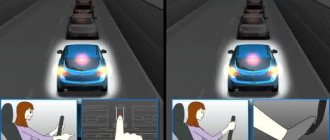
In a situation where the car owner uses a remote key fob to lock the doors, the corresponding signal is sent to the antenna, which is directly connected to the central ECU. Then, from this control unit, the necessary signal is distributed to all doors, after which they are blocked. Also, when using the key fob, the alarm is immediately activated. It is worth noting that on some modern cars, at the moment when all the doors are locked using the central lock, the windows are also locked. Modern ECUs are programmed so that in the event of an accident, the locking will stop automatically. For this purpose, the car has a corresponding shock sensor.
Installation instructions
Installation of the device is carried out as follows:
- First, the plastic door trim is removed and a location for installing the unit is selected. When choosing a location, it is necessary to take into account the location of the window lifter elements. According to many experts, it is better to install the system in the lower left corner of the door.
- The next step is to install the lock activators, each of which is mounted separately on each door. It is necessary to drill the corresponding holes in the structure in advance and secure them with self-tapping screws. After this, the activator must be connected to the rod. Next, the activators need to install clamps on the manual control elements of the central locking.
- The wiring is being laid - All wires must be securely fixed; plastic clamps can be used for this. They should not be placed at the bottom of the door, since moisture usually collects in this place, so it is better to choose a place between the door and the body, installing a rubber tube here in advance. Thanks to it, the wiring can be protected from damage.
- The next step will be to dismantle the control panel. Having done this, the old wiring from the window regulators can be removed and a new one can be laid, which is subsequently connected to the drive.
- After this, the activator drives are connected. When all these steps are completed, the wiring must be pushed under the control panel on one side, and into the glove box on the other side. A pass-through pipe is mounted into the rack; a screwdriver may be required to install it.
- Now a fuse is connected to the connector and this circuit is connected to the central locking power supply, the entire structure is installed under the center console. The cable from the central locking system must be connected to the on-board network, plus to the fuse, minus to the body. Assembly is carried out in reverse order.
Loading …
Children's castle
Also, in addition to a centralized door locking system, modern cars are often equipped with child locks. This was done for the simple reason that a child in a car can behave unpredictably, and due to his sluggishness and carelessness, he can fall out if he accidentally opens the door. Especially for this purpose, there are corresponding switches on the inside of the rear doors, when activated, it will be impossible to open the door from the passenger compartment. Typically, to activate the child lock, you must turn the switch using the car's original key.
These structural elements are installed on both sides and are operated separately. Such a device itself is located in close proximity to the standard door lock. It is worth noting that such mechanisms can only be deactivated or, on the contrary, set manually. It is impossible to remotely activate or vice versa disable the function, since it is necessary to turn the corresponding drive, which is responsible for the operation of the handle located in the car interior.
Connecting an alarm to the central locking system with a negative and positive pulse
In this case, when a minus is applied to a pair of lock wires, they close or open. Finding such wires is relatively easy using a probe (lamp). You should alternately close the wiring that comes out of the car doors on the driver’s side. As soon as the right pair of wires is found (the door opens or closes), the problem can be considered solved.
In those cases where it was not possible to find the wires, you will have to “dig” into the central locking unit. You will need to find a special relay in it that is responsible for closing/opening the doors, and then solder the security system wiring into it.
Working with a lock controlled by a “plus” pulse is similar to the scheme described above. Only the required pair of wires in this case, as you yourself understand, will have a plus polarity. In other words, positive wires should come from the alarm.
The connection diagrams for the voiced types of central locking with a built-in relay will therefore be as follows:
- “Negative” pulse: NC (normally closed) contacts are not needed, NR (normally open) contacts are connected to the “minus”, common contacts go to the control wires.
- “Positive” impulse: open contacts are connected to positive, closed contacts are not used, common ones, as in the previous version, are connected to the found control wiring.
Double locking system
Also, some modern cars are equipped with a security system such as double door locking. In this case, we are talking about turning on the locks from inside the cabin, as well as from outside the car. The use of such a structural element significantly makes it possible to protect the vehicle from the actions of intruders. With such an activated system, even if a thief breaks the glass and tries to open the door from the inside, he will not succeed. As for activating the option, this requires pressing the door lock button twice. The same procedure must be followed when unlocking the locks. It is noteworthy that even such a modern and useful system cannot boast of the absence of shortcomings. There is only one characteristic minus here, and it completely negates all the advantages. Provided that if the entire centralized door locking system fails, the motorist simply will not be able to get into the interior of his car.
Door stop
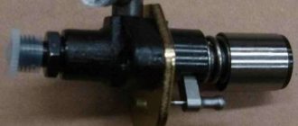
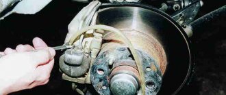
To limit the opening angle and hold the door in the open position, each door is equipped with a spring stop 1. The ends of the stop, which serve as the axis of its rotation when opening the door, are attached to the body pillar with a bracket 6, which is secured with screws 7 screwed into a plate 5, held in place by a holder 4 , thanks to which the screws can be removed completely. The dimensions of the holder allow the plate to be moved when adjusting the door hinge.
When the door is opened, the shank 2 of the roller, mounted on the amplifier 8 inside the door, rests against the stopper loop, thus delaying further opening of the door. In this case, the limiter jumper 3, due to its elasticity, compresses the roller, preventing the door from closing under the influence of its own weight. The door opening angle with this design is not adjustable. To prevent the door from creaking, the stopper must be periodically lubricated.
Rice. Position of the lock and latch when closing the door: I - direction of door movement; II - direction of rotation of the rotor; a - the door is completely closed; b - the door is closed by one tooth; c — the door begins to close; 1 - rotor; 2 - latch; 3 - cracker; 4 — clamp; 5 — latch shelf
Conclusion
Automobile manufacturers do everything necessary to ensure that operating a car is not only a comfortable experience, but also completely safe. It is for this purpose that all sorts of additional systems and auxiliary mechanisms are being introduced into modern vehicles. In particular, almost any car is equipped with a central locking or centralized door locking system. This option allows you to open all the doors in the car at once and without making any physical effort, since the locking process is carried out automatically, but if necessary, it can also be done manually.
Door fastening
Each door at the front end is suspended from the body on two hinges. The cheek 1 of each hinge, adjacent to the body pillar b, is secured with screws 4 screwed into a plate 5 held inside the pillar by a holder 3. The dimensions of the holder allow the plate to be moved during adjustment. The hinge cheek 10, adjacent to the door, is attached to it with bolts 8, which pass through the holes in the door reinforcement V and are screwed into the threaded holes of this cheek.
To prevent dust from penetrating inside the front and rear doors, the cheek piece 10 of the hinge passes through a sponge seal 11, which is held by a holder 12 welded to the door. To protect the body from dust in the places where the front door hinges are attached, the cheek piece 1 of the hinge passes through a sponge seal 2 glued to the body pillar. and the mounting holes in the rack are closed with a rubber plug 7. The cheeks of the hinges are steel; They are made from a special rolled profile that is cut. The cheeks are connected with a finger. The finger is lubricated through the hole in the head of the cheek. The described fastening allows you to adjust the doors, that is, move them in any direction: up, down, forward, backward, inward and outward. This adjustment ensures the correct position of the door, determined by a uniform gap around the perimeter of the door and the absence of steps between the surface of the door and the areas of the body adjacent to it.
Rice. Door stop (horizontal section): I - door in open position; II - door in closed position; 1 - limiter; 2 — roller shank; 3 — limiter jumper; 4 — plate holder; 5 - plate; 6 — bracket; 7 - screw; 8 — door amplifier
Rear door glass
In the rear door window, due to the impossibility of completely lowering the glass due to the arched projection of the door above the wheel, the sliding glass is narrowed, and the additional glass, which is made fixed, is enclosed along the contour in a rubber seal.
Rice. Door seal: a - section along the top of the door window; b - cross-section along the B-pillar through the windows of the front and rear doors; c - cross-section along the door threshold; 1 - edge of the facing lining; 2 — external seal; 3 — arch of the headliner; 4 — internal seal; 5 — sliding glass; 6 - groove; 7 — door frame; 8 — threshold facing; 9 - outer door panel
KV-Rapid › Blog › Car door locks and their adjustment
On many old cars, what can I say, even on completely new domestic ones, there is often a problem when the doors close only with a slam.
The culprit here is not the hard seals or sagging, but the banal lack of adjustment of the locks. In order for the doors on your car to close with one finger, you do not need to have a magical gift or the skills of a professional auto mechanic. You only need our theoretical recommendations.
Before arming yourself with wrenches and screwdrivers, try oiling both parts of the lock (one mounted on the post, the other mounted directly into the door). Perhaps by blurring the details and developing them a little, you will be happy with the resulting effect. But if that doesn't help, then here's what to do next:
- Determine the reason why the doors on your car do not close well. The part of the lock that is installed on the counter can be very far from the lock part mounted in the door. As a result, the door closes only under the influence of force. Again, the problem may be with the part that is mounted on the post, but now it may not be perfectly positioned relative to the second part of the lock. The lock may simply be damaged.
-It is very easy to determine the cause. You need to slowly close the door and look through the crack to see how the parts of the lock behave. If the hinge is difficult to reach the lock, or if it is not quite correctly positioned relative to it, you will easily notice this. Damage to the lock can only be assessed by examining it: if there are significant abrasions on it or on the hinge, chips are a clear sign.
- Having found the cause, we proceed to troubleshooting. If the door begins to close poorly for reason No. 1, then it is necessary to loosen the lock on the post, or place a washer under its base, which will bring the hinge a little closer to the lock and allow it to work as it should. If reason No. 2 is to blame, then you just need to adjust the position of the loop through repeated trials and adjustments. Finally, for reason #3, the lock parts simply need to be replaced.
-Be prepared for the fact that unscrewing the bolts that secure the hinge may not be easy. To do this, use an impact screwdriver.
-After finishing the adjustments, do not rush to fold the instrument. Generously lubricate both the lock parts and the door hinges with oil - this will further enhance the adjustment effect.
That, in fact, is all the work. You may only encounter difficulties when setting up the first door. Once you understand the general principle, adjusting the locks won't take much time.
Source
Window lifter
For the sliding windows of 1 doors, the same window lifters with a cable drive are used. The glass lifters of the right and left doors are interchangeable, and the front and rear doors differ only in the length of the cable. The window regulator is secured to the door with three screws screwed into the window regulator body.
The window lift cable is fixed to drum 17 and in the working position is tensioned in the form of a triangle. The axis of the upper roller 4 is riveted to the reinforcement of the inner door panel.
The lower roller 14 is fixed in a fork 12, which is constantly pulled down by a spring 11 to compensate for the pulling of the cable. To reduce the friction of the cable on the side of the roller and ensure silent operation, the hook 10 of the fork is fixed at one point, as a result of which the plane of rotation of the lower roller 14 can deviate in accordance with the movement of the cable 16 along the grooves of the window lift drum 17.
Rice. Sliding glass and front door windows: 1 - glass; 2 — internal glass seal; 3 - window sill invoice; 4 - upper roller; 5 — cable clamp; 6 — external glass seal; 7 — external decorative trim; 8 — sliding glass holder; 9 — lower roller bracket; 10 - fork hook; 11 - spring; 12 - fork; 13 — buffer bracket; 14 - lower roller; 15 - buffer; 16 — cable; 17 - drum; 18 - handle
The cable and glass are moved by rotation of the drum using the window lifter roller gear and the drum ring gear 17.
The upward movement of the glass is limited by the glass resting on the upper groove fixed to the door frame. The downward movement of the glass is limited by the stop of the glass clip 8 in the rubber buffer 15, inserted into the bracket and fixed to the inner panel of the door.
The windows are fixed in any position by a brake spring placed inside the window lifter brake cup. The correct operation of the brake spring is checked by the amount of free play of the handle 18, which should be no more than 35 mm along the chord for the tip of the handle. Due to the fact that normal operation of the window lift can only be ensured with proper cable tension, elongated holes are made to attach the lower roller bracket 9 to the inner door panel, allowing the bracket to be installed in the desired position. Cable 16 must be well lubricated. If bracket 9 is loosened, the cable may come off the rollers and the window regulator will stop working. In this case, you should remove the inner handles and door trim, correct the position of the cable on the drum and rollers, pull bracket 9 down and secure it so that the cable is stretched like a string.
Rice. Pivoting glass of the front door: 1 — glass frame seal: 2 — pillar; 3 - nut; 4 - bracket; 5 - axis; 6 - spring; 7 — washer; 8 — seal for the open edge of the glass; 9 — bracket; 10 - button; 11 — handle; 12 — vaschelka