Schematic electrical diagrams, connecting devices and pinouts of connectors
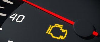
VAZ cars have a fault diagnostic system that allows you to read and decipher error codes. Most VAZ-2110 cars have an old type “January-4” controller installed. The activation of “CHECK ENGINE” is considered a malfunction detection signal. Troubleshooting in such a controller is simple - error codes are calculated starting from the number 12 and ending with 61. For more modern VAZ models, ELM-327 electronic adapters with the OBD-II program are suitable.
Where is the diagnostic connector located?
On different cars of the VAZ family, the socket is located in different parts of the car. Let's look at a few models as an example:
- on the VAZ-2112 , as on the 2110 , as well as the 2111 , the socket is located to the right of the driver’s seat, immediately under the column;
- on models 2108 , 2109 and 21099 , the socket you need is located under the glove compartment, on a special shelf;
- on cars with a europanel it can be found in the center of the console, near the cigarette lighter. A special decorative cover is used to disguise it;
- Lada Kalina cars the connector is near the gear shift lever, it is also hidden under a special cover;
- On a Lada Priora, look right behind the glove compartment, on the wall.
VAZ 2110
Installing the on-board computer State X1M in nine and other little things.
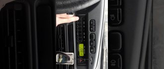
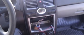
Hello everyone, with this self-liquidation regime, work is difficult, and therefore there is no money, but we are holding on. Nothing much is done to the car. Not long ago, my father bought himself a BC staff x1m, which is the size of a standard button 2112. A very convenient thing, it has all the necessary data on engine operation, reading errors, etc. But it didn’t work out; for some reason it didn’t work correctly on the two-wheeler. I tried to connect it to myself, everything was clear, so be it, we decided that it would stand with me. I decided on the location quite quickly; for me, it should be at the level of the instrument panel, so that I can see the necessary and interesting readings without being distracted from the road. Moved the emergency button to the place of the cigarette lighter.
The new Granta cigarette lighter stuck into the glove compartment, because I don’t smoke and only use a phone charger. The factory chip reached under the cigarette lighter.
I took a plug for the square nine buttons, cut out a square hole of the required size, and placed the beadboard in it using cyanoacrylate glue.
The connection is elementary. 5 wires. Black - ground Red - plus constant Red with a stripe - plus from the ignition White - backlight Gray - to-line from the diagnostic connector. I removed the top part of the panel, and underneath it there is no factory chip. Either for connecting the factory on-board signal, or for the radio, but I used it for the new BC, it has exactly the four wires needed. I only had to bring one wire from the diagnostic connector. I connected it, everything works, I put the plug in place, I thought that this button would look awkward, but in my opinion it is quite appropriate and conveniently located. I immediately set the fan switch-on temperature on the on-board vehicle to 98°, instead of the factory setting of 105, it seems. The most necessary functions for me are average and instantaneous flow rates, error codes and reset, and setting the fan operating temperature. I'm happy with the bortovik. I recommend it to everyone.
I also embedded additional buttons into the front socket to turn on the amplifiers, sometimes a necessary issue. Later I will buy nicer buttons with ring lighting.
I ran a 4 kWmm wire from the battery to power the radio and installed a 15A fuse. And he took the mass from the body from the engine shield. The sound has become a little better and, best of all, the mafon no longer turns off when the engine starts.
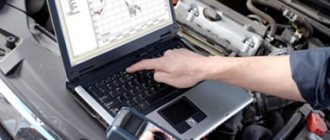
How to diagnose a car
- Connect contact “B”, which has the diagnostic block and “ground”;
- Turn the ignition key to the third position, do not start the car;
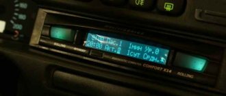
- First, the “CHECK ENGINE” lamp displays code 12 with 3 flashes. It shows that the diagnostic programs are working. On the VAZ 2110 this happens in this order: the lamp blinks briefly 1 time (which should be considered the designation of number 1). After a pause lasting at least 2 seconds, it flashes 2 times in a row (two). So we got the number two. And this is repeated 3 times so that the driver understands these signs;
- After the diagnostic program has declared its serviceability, it will begin to display error codes, if there are any, of course. In the same way - flashes and pauses.
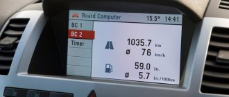
—76— Installing the on-board computer
Salam in half. Gave it to me for my birthday. in early December on-board computer... This is a very useful and necessary crap that I have dreamed of all my life!
Bet with my little brother
, for which many thanks to him!
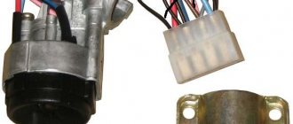
I don’t see much point in describing the installation, because everything is written in the instructions - a monkey will figure it out. The only problem I encountered is that I don’t have a chip for the BC itself in my car, and there isn’t one at all... Or rather, there was a chip, but for the old connector - 4-pin - like on the headlights, it’s square. Got it? How did you not understand? Go out into the yard and open the hood - it will immediately become clear what I mean! In short, I’ll simply put down a photo from the internet.
But it’s not at all clear to me why the hell they would shove this chip under the panel... Eniway, I should have bought exactly the same one, only “dad”, because there’s a mother in the panel. And another 9-pin chip for the BC itself and a collective farm adapter (yes, yopta, the kit included only an ambient temperature sensor and a wire for the K-line). But where can you find the adapter itself, and it costs about 250 rubles, for two pieces of plastic and 4 wires, wow, the damned capitalists went wild.
In theory, there are 13 contacts on the back of the BC, but 2 of them are occupied by a temperature sensor, and the other 2 by the HBO. But I’m not going to install gas in the near future, because I’ve set myself the goal of trashing the entire ecology of my vast Motherland with roaring exhaust on pure, like a baby’s tear, 92 gasoline. “Only gasoline, only hardcore!” (With)
In short, I called all the stores in the area, no one knows what kind of 9-pin animal this is and what they eat it with. There are chips for gas pumps, for faust cartridges, even for a catapult, but not for the VAZ2114 BC. The “workhorse” saved me, where the guy immediately understood what I was talking about. I bought a chip for “heated seats VAZ-2110” with 9 wires!)
Okay, wires - check, chips - check, BC - check, straight hands - set, checklist complete. Let's get started with the installation... A fool can insert a chip into a chip, but getting the ambient air temperature sensor through is a technical task. I had a lot of trouble with this asshole...
The sensor itself is very fragile, like the tail of a shrimp, there are plates like that... In short, don’t stop breaking/bending it. And you need to file it under the hood. Therefore, I decided to push the chip itself from under the hood into the interior so as not to disturb the sensor. But after several failures in trying to insert a watermelon into a hole the size of a lemon, I gave up on everything, took a thick wire, electrical tape and tied this crap to the wire, which I had already stuffed into the cabin. I already pulled this hefty turnip out of the cabin, what a damn thing to do. Then, by touch, like a real gynecologist/proctologist, he pulled the temperature sensor wire under the panel all the way to the BC, bending around the fancy plastic lugs of the stove body, damper cables and other, generally very important and necessary, but not very convenient crap to bend around.
After the hardest part - stuffing in the temperature sensor - everything is much simpler)
You need, like, 5 wires: 1 - Plus
(was on the old chip)
2 - Minus
(was on the old chip)
3 - Ignition
(was on the old chip)
4 - Dimensions
(was on the old chip)
5 - Fuel
(picked it from the dashboard, just crashed into the chip)
OK. Battery - off, chips-on-twist - check, temperature sensor - set. Checklist complete. Let's start pulling the wire under the K-line. Everything is simple here, stretch one thin wire from the center of the panel to the front passenger’s feet.
We put on the battery terminal, poke it - we rejoice and push our battery into its rightful place.
Well, that’s it, then we set it up either at random or using the instructions.
One day I was walking somewhere and decided to capture this moment. My nine-nine, my mother's aster, some fucking snowdrop and the fierce evil of my neighbor)) In my opinion, he went a little too far with the badboy. But to each their own markers, guys. For some, blue diodes, for others, spare parts for the price of an airplane, for others, it’s better to put a long bolt on your cart (you should even clear the snow, shame!), and for some, weld more metal onto your cart. It's a race, huh?)
Spring to everyone, less cold! z.y. - If you have any questions about connection, please contact us. z.z.y. - and that’s the most important thing... come and visit the little one, make the guy’s day!))
Source
Deciphering error codes
The first character is a letter and indicates a fault block:
- B - body;
- C - suspension;
- P — engine (ECM, gearbox);
- U - data exchange bus.
The second character is a number, code type:
- 0 — SAE (standard);
- 1.2 - OEM (factory);
- 3 - reserved.
The third character is a number, system:
- 1, 2 - fuel system;
- 3 - ignition system;
- 4 — reduction of exhaust gas toxicity;
- 5 - idle;
- 6 - ECU or its circuits;
- 7, 8 — transmission (automatic transmission).
The fourth and fifth characters are numbers, the error code itself.
To diagnose a VAZ 2114, 2113 or update the ECU firmware, car owners, diagnosticians or mechanics need to know the location of the OBD2 diagnostic connector, as well as its pinout and type. To flash the electronic unit or replace it, you also need to know the location of the ECU and the purpose of the pins.
First conclusions
After analyzing the overall results, we can draw the following conclusions:
- compression of 0-4 atmospheres indicates a probable burnout of the piston, valve or cylinder head gasket;
- compression 4-6 atm. usually indicates broken piston rings or partitions between these rings;
- if the compression in each cylinder is approximately the same and amounts to 8-10 atmospheres, then this indicates wear of the cylinder-piston group, so it is necessary to prepare for the upcoming engine overhaul;
- A new and run-in engine can have a compression of 12-12.5 atmospheres.
If a car with decent mileage produces results equal to or higher than normal, this indicates that oil may have gotten into the cylinders. The probable reason for this is wear of the cylinder-piston gear or valve guides.
Now it is necessary to compare the obtained data with the results of a visual inspection.
So, everything has been examined, an analysis has been carried out and the problematic cylinder has been found. But the overall picture still requires clarification. In this case, it is necessary to check the cylinder for leaks.
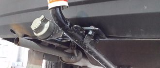
Where is the diagnostic connector for the VAZ-2114
VAZ 2108-2115 with a “European panel”, the diagnostic connector is located in front of the gearbox, directly under the cigarette lighter. The block is closed with a decorative cover. On injection models since 2002, a 12-pin rectangular connector has been used.
The location of the connector is indicated on the diagram in position No. 8 . The following are visual photos of the diagnostic block.
Photo of the block location:
About the ECU and its location is written in the article “Diagnostics of VAZ 2114”. The following shows the pinout of the OBD2 connector and the assignment of contacts of the electronic control units that were installed on the Fourteenth VAZ models.
Connector type No. 1—16-pin OBD-II connector in the shape of a trapezoid:
Brands and years: some models after 2002 with control systems BOSCH MP7.0 Euro-3, BOSCH M7.9.7, January-7.2, January-7.3.
Connector type No. 2 - 12-pin rectangular connector: Make and year: all injection models, except for some models after 2002 that have an OBD-II connector
VAZ 2109 diagnostic block - ease of car maintenance
Installation location of the diagnostic block for VAZ 2109
Communication with the electronic control unit (ECU) of the main components of the car is carried out by the diagnostic block. On a VAZ 2109 car, the diagnostic block is located on the right side under the dashboard next to the ECU. A special diagnostic tool or counting the number of flashes of the built-in “CHECK ENGINE” lamp can read the vehicle fault codes that are stored in the ECU memory. The article suggests getting acquainted with the procedure for reading fault codes in a VAZ 2109 car and how to perform all operations yourself.
OBD1 pinout - 12 PIN (GM12)
Description:
OBD1 (GM12) connector is rectangular in shape, consists of 12 contacts.
Brands and years:
All injection models, except for some models after 2002, which have an OBD-II connector.
Access and location:
Open access. Located next to the ignition switch, partially covered by the steering column cover.
Pinout:
| M | L | K | J | H | G |
| A | B | C | D | E | F |
| Key * | |||||
* Connector Keying - A design element of a removable connector that ensures the correct orientation of the plug and socket.
Example in the photo:
Conclusions and their purpose:
| Conclusion | Color | Purpose |
| A | Weight | |
| B | L-line diagnostics (not always routed) | |
| D | CO potentiometer (not always diluted) | |
| G | Fuel pump control | |
| H | Power supply +12V (not always wired) | |
| M | K-line diagnostics |
Elm 327 does not connect to the ECU (electronic control unit): what to do?
If the elm327 adapter does not connect to the VAZ 2114 ECU, then it is possible that you purchased version 2.1 or version 1.5, which was converted from 2.1. The fact is that such devices use a different version of the Bluetooth module, which supports only 2 protocols out of the available 6. In this case, the adapter connects to a smartphone/tablet, but when you try to connect to the car’s ECU, a message appears that the ECU is not responding.
If your adapter elm327 VAZ 2114 really belongs to version 1.5 and has all six protocols, then you can correct the work and adapt to the ECU commands by manually entering initialization lines.
Such attentive and responsible attitude towards the technical condition of your own car will be a guarantee of safety for you and your loved ones. Trips of any distance will no longer be a test of your own luck and will turn into comfortable trips that bring maximum pleasure.
It should be noted that such situations arise quite rarely. As a rule, a high-quality car scanner purchased from a reputable seller does not present the owner with any unpleasant surprises. The main thing is that during the process of purchasing/ordering a device, the make of the car, the year of its manufacture, etc. are taken into account. It is advisable to check with the seller how well the elm327 adapts and works on the VAZ 2114.
OBD2 pinout - 16 PIN
Description:
The OBD2 connector is trapezoidal and consists of 16 pins.
Brands and years:
Gasoline passenger cars and light commercial vehicles manufactured or imported into the United States since 1996 (US CARB and EPA legislation) and in Europe (EOBD) since 2000-2001 (European Union Directive 98/69EG) and Asia (mainly since 1998). ).
Access and location:
Pinout:
| 1 | 2 | 3 | 4 | 5 | 6 | 7 | 8 |
| 9 | 10 | 11 | 12 | 13 | 14 | 15 | 16 |
| Smaller side of trapezoid | |||||||
Example in the photo:
Conclusions and their purpose:
| № | Color | Purpose |
| 2 | J1850 Bus + | |
| 4 | Body grounding | |
| 5 | Signal Ground | |
| 6 | Line CAN-High, J-2284 | |
| 7 | K-line diagnostics (ISO 9141-2 and ISO/DIS 14230-4) | |
| 10 | J1850 Bus- | |
| 14 | Line CAN-Low, J-2284 | |
| 15 | L-line diagnostics (ISO 9141-2 and ISO/DIS 14230-4) | |
| 16 | Power supply +12V from battery |
Diagnostic connector pins for used protocols
Pins 4, 5, 7, 15, 16 - ISO 9141-2.
Pins 2, 4, 5, 10, 16 - J1850 PWM.
Pins 2, 4, 5, 16 (without 10) - J1850 VPW.
The ISO 9141-2 protocol is identified by the presence of pin 7 and the absence of pins 2 and/or 10 on the diagnostic connector.
If pin 7 is missing, the system uses the SAE J1850 VPW (Variable Pulse Width Modulation) or SAE J1850 PWM (Pulse Width Modulation) protocol.
All three data exchange protocols operate via a standard OBD-II J1962 connector cable.
The correct connection diagram for a 12 PIN block with a 16 PIN adapter
What factors may influence measurements?
- only a new or well-repaired car can have a compression of 12 atmospheres, for example, after an engine overhaul;
- a cold engine that has not reached operating temperature will have significantly lower compression;
- if the battery is weak or begins to “crumble”, then the engine will not turn so fast, so in this case the compression will be less;
- compression increases due to the combustion of oil in the cylinders - as a result of its combustion, the connection is sealed.
- Having recorded all the measurement data, it is necessary to analyze it. The spread of results for all cylinders should not exceed one atmosphere. For example, if in one cylinder the compression is 9 atmospheres, and in the other three – 11, then in this case you need to think about it. To more accurately determine the nature of the malfunction, it is necessary to carefully monitor the pressure gauge readings, or more precisely, how the pressure increases with each crankshaft revolution.
OBD 2 connector
OBD 2 is an international diagnostic standard. It regulates the requirements for diagnostic equipment, unifies error codes - in general, almost everything related to diagnostics.
The VAZ 21099, produced since 2002, began to install a diagnostic connector that complies with the OBD 2 standard. Externally, it differs from the VAZ one in its trapezoidal shape:
You can carry out diagnostics on the injection VAZ 21099 using a car scanner (for example, based on the elm 327 processor). This is done with the preliminary installation of an application sold with a licensed scanner, even using a smartphone. By logging into the installed application, you can easily set error codes and also delete them.
True, the market is flooded with Chinese products that “do not see” the ECU of domestic cars, so you have two options:
If you have an “old” GM12 block on your car, then the following adapter will help you connect to the scanner or cable:
However, in cases where you need to output errors to the computer, but there is no adapter, you can connect by independently connecting to any of the connectors for diagnostics, using the following correspondence diagram:
see also
Comments 122
I had a diagnostic connector on my '98 car. And since I always had a repair book on hand, I quickly identified all the unclear connectors from it :) but there was no sensor in the gearbox. There is a sensor for the beige one, but the box is already 2110
The TDC sensor was installed before 1995, emnip.
How is driving the Ex-85, I wonder?! )))
A few years ago I bought a friend a Soviet instrument panel 2108 with a test mileage of 00002 at a very ridiculous price.
There is that same TDC sensor, now screwed into the gearbox bell (the one from the USSR). If you are interested, I will send it. The condition is really bad.
Thank you, there is such a thing, but without a tester it’s more likely just for beauty)
How can a tester carry out diagnostics? And what kind of tester?
Replacing the fine fuel filter
The fine gasoline filter is located under the hood if the car has a carburetor. It is installed on the fuel hose that goes to the fuel pump. To replace the fine filter, you only need one screwdriver. It is recommended to replace it after approximately 15 thousand kilometers. On fuel-injected cars, such a filter is located at the rear under the body. You will learn about its replacement in another review.
Work order:
- Unscrew the screws of the clamps.
- Pull the filter out of the hoses.
When replacing the filter, pay attention to the direction of the arrow on the housing, which should be directed towards the fuel pump.
The quality of the fuel affects the condition of the filter. If you refuel your car at different gas stations that you are not sure about, then inspect the filter more often.
A clogged filter element leads to jerking when driving at high speeds. And if the filter is heavily soiled, then even at low speeds. If a dirty and cloudy filter element is visible through the transparent housing, replace it. This will only take a few minutes, not including shopping at the store. But you will maintain normal engine operation and extend its service life.
Useful video
You can get more information about connecting to the diagnostic connector from the video below:
VAZ cars are very popular due to their affordable price, reliability and availability of spare parts on the car market. Many drivers are familiar with the design of the car, so they can carry out repairs themselves. The article talks about self-diagnosis, examines diagnostic equipment, including an adapter for diagnostics on a VAZ car.
ODB connector pinout: convenient pin layout
In order to personally diagnose a VAZ-2110 car through the connector located under the steering column, you need to know where to connect this or that equipment. This task is greatly facilitated by pinout, which is a diagram of the placement of contacts. It identifies the following main outputs:
- A – ground from the car battery is connected to this output;
- B – output is intended for connecting L-Line type equipment. It is not used on all modifications of the VAZ-2110, so be sure to pay attention to this when choosing a computer scanner or adapter;
- M – K-Line type devices are connected to this output. They are rightfully considered the optimal choice for self-diagnosis of the VAZ-2110, as they provide excellent interaction with any computer equipment;
- H – output to which power is supplied during diagnostic operations;
- G is a very important pinout element, since it is it that ensures safety control of all procedures performed and eliminates any short circuits or other emergency situations.
This designation of contacts will allow you to avoid mistakes when connecting diagnostic equipment, as well as perform all the necessary work efficiently. Now that you know the location of the ODB connector, as well as its main components, you can begin to assess the technical condition of the car.
Lada 2108 Safari › Logbook › Diagnostic block. + a little zap
General connection diagram:
It’s not important, but the USSSSSSSSR’s reserves are always pleasing to the eye, I dug up some samples:
Right mirror caps:
USSR dashboard)
Gasoline filter, thanks for fitting thebestofmyself
Gas supports of the 3rd door, because mine are already dead (:
Expansion tank, old stock, mine was leaky:
USSR tires EX-85 (EX is the early name of BL-85) and BL-85, also new and very old, respectively, 86th, 88th years)
Old-style stampings (more about them later) - 88) New 2 pcs. only(((
We found fittings for door cards 2108, i.e. old style, with a long handle. Where can I find the cards themselves)))) Thanks for the customization ///// /I can’t remember Nick(((((
P/S/ I'm looking for old-style cards in good condition