Each component and mechanism of the car is important in its own way. There is probably no system without which a car could function normally. One such system is the steering mechanism. This is probably one of the most important parts of the car. Let's look at how this unit works, its purpose, and structural elements. We will also learn how to regulate and repair this system.
Operating principle of rack and pinion steering rod
Rack and pinion steering
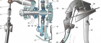
Rack and pinion steering is the most common type of mechanism installed on passenger cars. The main elements of the steering mechanism are the gear and the steering rack. The gear is mounted on the steering wheel shaft and is in constant mesh with the steering (gear) rack. Rack and pinion steering diagram
1 – sliding bearing; 2 – high pressure cuffs; 3 – spool body; 4 – pump; 5 – compensation tank; 6 – steering rod; 7 – steering shaft; 8 – rack; 9 – compression seal; 10 – protective cover. The rack and pinion steering mechanism works as follows. When you rotate the steering wheel, the rack moves left or right. As the rack moves, the steering rods attached to it move and rotate the steered wheels.
The rack and pinion steering mechanism is distinguished by its simplicity of design and, as a result, high efficiency, and also has high rigidity. But this type of steering mechanism is sensitive to shock loads from road unevenness and is prone to vibration. Due to its design features, rack and pinion steering is used on front-wheel drive vehicles
Worm steering gear
Worm gear diagram
This steering mechanism is one of the “obsolete” devices. Almost all models of domestic “classics” are equipped with it. The mechanism is used on off-road vehicles with dependent suspension of the steered wheels, as well as in light trucks and buses.
Structurally, the device consists of the following elements:
- steering shaft
- worm-roller transmission
- crankcase
- bipod
The worm-roller pair is in constant engagement. The globe worm is the lower part of the steering shaft, and the roller is attached to the bipod shaft. When the steering wheel rotates, the roller moves along the teeth of the worm, due to which the steering bipod shaft also rotates. The result of this interaction is the transmission of translational movements to the drive and wheels.
The worm type steering mechanism has the following advantages:
- possibility of turning wheels to a greater angle
- shock absorption from road irregularities
- high force transmission
- ensuring better machine maneuverability
Manufacturing the structure is quite complex and expensive - this is its main disadvantage. Steering with such a mechanism consists of many connections, periodic adjustment of which is simply necessary. Otherwise, you will have to replace damaged elements.
Features of the unit and design
Cars use a kinematic method of changing the direction of movement, implying that turning occurs by changing the position of the steered wheels. Usually the front axle is steered, although there are also cars with a so-called steering system. The peculiarity of working in such cars is that the wheels of the rear axle also turn when changing direction, albeit at a smaller angle. But so far this system has not received widespread use.
In addition to the kinematic method, the technique also uses the power method. Its peculiarity is that to make a turn, the wheels on one side slow down, while on the other side they continue to move at the same speed. And although this method of changing direction has not become widespread in passenger cars, it is still used on them, but in a slightly different capacity - as a directional stability system.
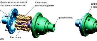
This car assembly consists of three main elements:
- steering column;
- steering gear;
- drive (system of rods and levers);
Steering unit
Each component has its own task.
The principle of operation of a car's power steering
To understand how a car’s power steering works, let’s consider several options, or rather different wheel turning situations. One of the most common situations is when the car is standing still, but with the engine running. In this case, the liquid is simply pumped from the tank through the system and back into the tank.
Another very common situation is when the driver turns the steering wheel.
. In this case, the torque is applied to the shaft, and subsequently to the torsion bar, which in turn begins to twist about its axis. As a rule, at such a moment the rotary spool does not work due to the wheels, due to which the liquid enters the cavities of the hydraulic cylinder under pressure (depending on which direction the steering wheel is turned). Excess fluid from the other cavity of the hydraulic cylinder flows back into the tank through the line. The basis of everything here can be considered the rod; due to the pressure of the liquid on the piston with the rod, the steering rack can move, and accordingly the wheels can turn.
The video shows the operating principle of the hydraulic steering rack
There is no less a situation when the driver holds the steering wheel in one position or even turns it all the way. Many experts say that this is the most difficult moment for power steering. In such a situation, the entire load goes to the power steering pump, since the distributor cannot return to its original position. Most often there is noise, vibration or other moments are possible. To get rid of this, just align the wheels and start moving.
Whatever the situation, the mechanism and principle of operation of the power steering is designed in such a way that in the event of loss of performance of one of the elements. All steering remains operating as normal, but with steering effort.
Steering column
Transmits the rotational force that the driver creates to change direction. It consists of a steering wheel located in the cabin (the driver acts on it, rotating it). It is firmly mounted on the column shaft. The design of this part of the steering very often uses a shaft divided into several parts connected to each other by cardan joints.
This design was made for a reason. Firstly, this allows you to change the angle of the steering wheel relative to the mechanism, shifting it in a certain direction, which is often necessary when assembling the components of a car. In addition, this design makes it possible to increase the comfort of the cabin - the driver can change the position of the steering wheel in terms of reach and tilt, ensuring its most comfortable position.
Secondly, the composite steering column tends to “break” in the event of an accident, reducing the likelihood of injury to the driver. The bottom line is this: during a frontal impact, the engine can move back and push the steering mechanism. If the column shaft were solid, changing the position of the mechanism would lead to the shaft with the steering wheel exiting into the cabin. In the case of a composite column, the movement of the mechanism will only be accompanied by a change in the angle of one component of the shaft relative to the second, and the column itself remains stationary.
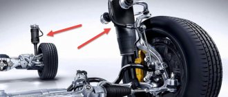
Elements of spring dependent suspension
The main components of the spring dependent suspension, in addition to the metal beam, are:
- elastic element (spring);
- damping element (shock absorber);
- reaction rods (levers);
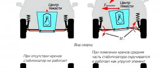
- anti-roll bar.
The most popular suspension of this type has five levers. Four of them are longitudinal, and only one is transverse. The guide devices are attached to a rigid beam on one side, and to the car frame on the other. These elements ensure that the suspension absorbs longitudinal, lateral and vertical forces.
The transverse lever, which prevents the bridge from moving due to lateral forces, has a separate name - “Panhard rod”. There are solid and adjustable Panhard rods. The second type of wishbone can also change the height of the bridge relative to the car body. Due to the design, the Panhard rod works differently during left and right turns. In this regard, the car may have certain handling problems.
Steering gear
Designed to convert the rotation of the steering column shaft into translational movements of the drive elements.
The most common mechanisms in passenger cars are the “gear-rack” type. Previously, another type was used - a “worm-roller”, which is now mainly used on trucks. Another option for trucks is “screw-type”.
"rack and pinion"
The rack and pinion type became widespread due to the relatively simple design of the steering mechanism. This structural unit consists of three main elements - a housing in which the gear is located and a rack perpendicular to it. Between the last two elements there is a constant gearing.
This type of mechanism works like this: the gear is rigidly connected to the steering column, so it rotates along with the shaft. Due to the gear connection, rotation is transmitted to the rack, which, under such influence, moves inside the housing in one direction or another. If the driver turns the steering wheel to the left, the interaction of the gear with the rack causes the latter to move to the right.
Often, cars use rack-and-pinion mechanisms with a fixed gear ratio, that is, the range of rotation of the steering wheel to change the angle of the wheels is the same in all their positions. For example, let's assume that to turn the wheels at an angle of 15°, you need to make 1 full revolution of the steering wheel. So, it doesn’t matter what position the steered wheels are in (extreme, straight), to turn by the specified angle you will have to make 1 revolution.
But some automakers install mechanisms with variable gear ratios on their cars. Moreover, this is achieved quite simply - by changing the angle of the teeth on the rack in certain areas. The effect of this modification of the mechanism is as follows: if the wheels are straight, then 1 revolution is required to change their position by the same 15° (example). But if they are in the extreme position, then due to the changed gear ratio, the wheels will turn to the specified angle after half a turn. As a result, the wheel's edge-to-edge steering range is significantly less than with a fixed-ratio mechanism.
Variable ratio rack
In addition to the simplicity of the device, the rack-and-pinion type is used also because in such a design it is possible to implement the actuators of the hydraulic booster (GUR) and electric power steering (EUR), as well as electro-hydraulic (EGUR).
"worm-roller"
The next type, the “worm-roller”, is less common and is now practically not used on passenger cars, although it can be found on VAZ cars of the classic family.
This mechanism is based on a worm gear. A worm is a screw with a special profile thread. This screw is located on a shaft connected to the steering column.
In contact with the thread of this worm is a roller connected to a shaft on which a bipod is mounted - a lever that interacts with the drive elements.
Worm steering gear
The essence of the mechanism is as follows: when the shaft rotates, the screw rotates, which leads to longitudinal movement of the roller along its thread. And since the roller is mounted on the shaft, this displacement is accompanied by rotation of the latter around its axis. This in turn leads to a semicircular movement of the bipod, which affects the drive.
The “worm-roller” type mechanism on passenger cars was abandoned in favor of the “rack and pinion” due to the impossibility of integrating a hydraulic booster into it (trucks still had it, but the actuator was remote), as well as the rather complex design of the drive.
Screw type
The design of the screw mechanism is even more complex. It also has a threaded screw, but it does not contact the roller, but a special nut, on the outer side of which there is a toothed sector that interacts with the same one, but made on the bipod shaft. There are also mechanisms with intermediate rollers between the nut and the gear sector. The principle of operation of such a mechanism is almost identical to the worm mechanism - as a result of interaction, the shaft rotates and pulls the bipod, and that in turn, the drive.
Helical steering mechanism
A hydraulic booster can be installed on the screw mechanism (the nut acts as a piston), but it is not used on passenger cars due to the massive structure, which is why it is used only on trucks.
The most common problems, their causes and solutions
Any unit is prone to breakdowns and the steering gearbox is, of course, no exception. It will be much easier for car enthusiasts to understand the cause of the problem and fix it as soon as possible if they are familiar with the main problems.
- The most common breakdown is a leaking steering gear. The presence of such a problem can be detected visually by the presence of oil under the car. The reason may be a leaking oil seal or corrosion of the input shaft. In this case, in the first case, during the repair it is necessary to install new oil seals, cuffs, and gaskets. And in the second case, the shaft should be polished, and then it is mandatory to carry out gas thermal spraying to normal dimensions.
- Feeling of a “tight” steering wheel. It appears due to an increase in the effort to turn the steering wheel. At the same time, in order to be sure whether there are reasons for repairing the steering gearbox, it is necessary to measure the level of steering wheel rotation gain with a special torque wrench. Then compare the obtained result with the data provided by the car manufacturer. If the indicators do not correspond to the established standards, it is necessary to carry out diagnostics on a specialized stand. This will help you find out the pressure, flow rate of the working fluid, as well as the presence of leaks in the gearbox. In this case, you should not try to repair the gearbox yourself. It would be much better, easier and more reliable to simply take it to a workshop. Or, if desired, replace it with a new one.
- Play in the steering wheel. This could be part of a faulty steering column crosspiece, or it could also be play in the gearbox itself. This requires not partial, but complete disassembly of the unit, examination of the condition of parts and replacement of worn elements. After the work has been completed, the device should be correctly adjusted on the stand.
- Knock in the steering gearbox. This type of malfunction can be identified by a noticeable “kickback” in the steering wheel. This problem occurs due to wear of the thrust bearings. It is necessary to replace damaged parts and then adjust the unit on the stand.
Drive unit
The drive in the steering design is used to transmit the movement of the rack or bipod to the steered wheels. Moreover, the task of this component is to change the position of the wheels at different angles. This is due to the fact that the wheels move along different radii when turning. Therefore, when changing the trajectory of movement, the wheel on the inside must turn at a larger angle than the outside.
The design of the drive depends on the mechanism used. So, if a car uses a “rack and pinion”, then the drive consists of only two rods connected to the steering knuckle (the role of which is played by the shock absorber strut) via a ball end.
These rods can be attached to the rail in two ways. Less common is their rigid fixation with a bolted connection (in some cases the connection is made through a silent block). For such a connection, a longitudinal window is made in the mechanism body.
A more common method of connecting rods is a rigid but movable connection to the ends of the rail. To ensure such a connection, a ball tip is made at the end of both rods. By means of a nut, this ball is pressed against the rail. When the latter moves, the rod changes its position, which ensures the existing connection.
In drives that use a worm-roller mechanism, the design is much more complex and consists of a whole system of levers and rods, called a steering linkage. So, for example, on the VAZ-2101 the drive consists of two side rods, one middle rod, a pendulum arm and steering knuckles with levers. At the same time, to ensure the possibility of changing the angle of the wheel position, the steering knuckle is attached to the suspension arms using two ball joints (upper and lower).
A large number of component elements, as well as connections between them, makes this type of drive more susceptible to wear and backlash. This fact is another reason for abandoning the worm gear in favor of a rack and pinion mechanism.
Basic faults
Common SRU malfunctions:
- wear of the rod end joint,
- slipping of the power steering pump drive belt,
- loss of PM tightness,
- destruction of the shaft bearing,
- loosening of fasteners.
Malfunctions are indicated by knocking, beating or increased play of the steering wheel, noise in the amplifier, and leakage of working fluid (with hydraulic control units).
The most common measures taken by service technicians at service stations when problems are detected with the control system are replacing the rod end (or the entire rod), boot, and power steering fluid. Repair of the power steering pump, rack, and gearbox may also often be required.
A special electronic training program dedicated to the steering system is available on the ELECTUDE platform. The training modules are aimed at a basic level of training and allow you to understand the principles of operation of the system, become familiar with the steering trapezoid, hydraulic and electric amplifiers, and understand the difference between direct and indirect control systems.
"Feedback"
It is worth noting that there is also a so-called “feedback” in the steering mechanism. The driver not only acts on the wheels, but through it also receives information about the characteristics of the movement of the wheels on the road. This manifests itself in the form of vibrations, jerks, and the creation of clearly directed forces on the steering wheel. This information is considered very important for correctly assessing the behavior of the car. Proof of this is the fact that in cars equipped with power steering and electric steering, the designers retained “feedback”.
Advanced Developments
This unit continues to be improved, so the latest achievements are the following systems:
- Active (dynamic) steering. It allows you to change the gear ratio of the mechanism depending on the speed of the car. It also performs an additional function - adjusting the angle of the front wheels when cornering and when braking on slippery roads.
- Adaptive steering (steering by wire). This is the newest and most promising system. There is no direct connection between the steering wheel and the wheels; everything works due to sensors and actuators (servos). The system has not yet become widespread due to psychological and economic factors.
Steering-by-wire system
Operating principle of the autopilot
The autopilot is not an independent device; it must be connected to a gyrocompass or remote magnetic compass.
In Fig. Figure 2 shows a block diagram of the autopilot, explaining the principle of its operation.
Rice. 2 Connection diagram of the autopilot to the gyrocompass
The control panel has a switch S1.1, with which you can set one of three types of control:
- auto;
- follower;
- simple.
In automatic mode, five signals are generated to ensure that the vessel is kept on a given course. The vessel moves on a constant course when the operating modes of the propulsors change. In this mode, the autopilot circuit is connected to a gyrocompass or remote magnetic compass. Being under the influence of external disturbances (wind, wave, etc.), the ship deviates from the given course. The task of the autopilot is to generate a signal, transmit it to the ship's steering device and ensure that the ship is kept on a given course. When the vessel leaves the course at an angle a, the selsyn-successor B2 transmits rotation to the selsyn-transformer B3, at the output of which the main control signal U1 = K1a is generated, proportional to the angle of deviation of the vessel from the course. Two other control signals are generated in the correction block (BC). These signals are formed from the signal by differentiating U2=K2α and integrating:
(U3=K3∫otadt).
The sum of the signals U1+U2+U3 is fed to the amplifier input. The amplified total signal is sent through the switch to the motor M1 of the actuator. The M1 engine sets a certain position of the steering spools (RM) and ensures that the steering wheel is shifted to an angle p. Depending on the type of PM, the autopilot kit may include an IM-1 or IM-2 actuator. In the IM-1 device, the output roller has a rotational movement through a certain angle E, and in the IM-2 device, the output roller moves translationally through a certain amount 1.
The value E(l) determines the rudder shift speed, i.e. E = Кβ. From the selsyn-transformer B5, mechanically connected to the M1 engine, the feedback signal U5 = K5 V is removed, which serves to reduce the self-oscillations of the rudder blade.
Selsyn transformer B6, mechanically connected to the steering wheel, produces a feedback signal U4 = K4p. This signal limits the rudder angle and, together with the U1 signal, ensures that the vessel is kept on a given course (according to the law of undamped oscillations). To dampen the oscillations of the vessel relative to the line of a given course, i.e. to restrain the vessel, the signal U2 = K2a is used.
All five signals are summed, with signals U1 and U4 always out of phase.
In order to set a new course in automatic mode, it is necessary to turn the steering wheel (angle γ) to transmit rotation through a mechanical differential (MD) to the movable index of the repeater and the rotor of the synchronous transformer B3.
In the tracking mode (position of 2 contacts of switch S1.1), the gyrocompass “Standard-14” is disconnected from the autopilot circuit. The main signal U1 is generated by synchro-transformer B3 by manually turning the steering wheel through an angle y (U1 = K1γ). Signals U3 and U3 are not generated by the correction block, since in the tracking mode the power of this block is turned off. Signals U4 and U5 are generated in the same way as in automatic mode.
In simple mode, signals U1...U5 are not generated. Power to motor M1 is supplied from transformer T1 through buttons S6, S7 and switch contacts
S1.6, S1.7. As a backup (emergency) manual control of the steering spools is provided (with the M1 engine de-energized).
The receiver selsyn B1 ensures the operation of the heading repeater, and the selsyns B7 and B8 provide the operation of the axiometer.