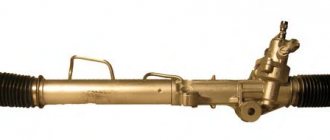
The design of the gas distribution mechanism of an internal combustion engine: purpose, principle of operation
The main purpose of the gas distribution mechanism (GRM ) is the timely supply of a combustible mixture of fuel and air (fuel-air mixture) into the combustion chamber and the removal of gases from the engine cylinders.
The work of the timing belt is to timely open and close the intake and exhaust valves, for which the valve mechanism is responsible.
Operating principle of the gas distribution mechanism
The entire working process of the gas distribution mechanism is based on the synchronous movement of two shafts - the crankshaft and the camshaft.
At the same time, the synchronization of movements ensures the timely opening of the intake/exhaust valves on the engine cylinders. When performing rotational movements of the camshaft, the cams step on the levers, which in turn act on the valve stems, which helps open the desired valves.
At the next turn of the camshaft, the cams are pushed away from the levers, which take their original positions, thereby closing the valves.
Timing device
The four-stroke internal combustion engine is the most common power unit used in the modern automotive industry. It got its name from the number of phases required to complete one cycle of work, or rotate the crankshaft by 720 degrees.
The injection phase of fuel or fuel-air mixture, compression of the working fluid by the piston, power stroke and exhaust gas release. In the model of an ideal engine, all phases are spaced apart in time, there is no overlap between them, which, in turn, ensures that the maximum possible operating values of power, torque and engine speed are obtained.
In practice, unfortunately, things are somewhat worse. The design of the gas distribution mechanism, which is responsible for the execution of the fuel injection phase and removal of exhaust gases, its diagram and principle of operation are the main topic of this article.
Diagnostics, maintenance, repair:
4.1. Diagnostics
Diagnostic signs:
- •Reduced internal combustion engine power:
- Reduced clearance;
- Incomplete fit of valves;
- Valve jamming. • Increased fuel consumption:
- Reduced clearance between valves and lifters;
- Incomplete fit of valves;
- Valve jamming. • Wear in internal combustion engines:
- Camshaft wear;
- opening the camshaft cams;
- Increased clearance between valve stems and valve bushings;
- Large gap between valves and lifters;
- fracture, violation of the elasticity of the valve springs. • Low pressure reading:
- The valve seats are soft;
- Soft or broken valve spring;
- Burnt out valve;
- burnt or torn cylinder head gasket;
- Unadjusted thermal gap. • High blood pressure.
- Reduced head height;
Timing belt classification
Modern car engines can be equipped with various types of gas distribution mechanisms.
The timing belt is classified into four categories:
- According to the location of the camshaft - upper or lower location;
- By the number of camshafts - one (SOHC - Single OverHead Camshaft) or two (DOHC - Double OverHead Camshaft);
- By the number of valves - 2, 3, 4, 5;
- Camshaft drive – chain, gear and toothed belt
The top position of the shaft in the cylinder head is the most common and effective. The opening and closing of the valves is carried out from the camshaft using levers (pushers) of the drive. This arrangement of the camshaft helps to simplify the overall design of the engine, reduce its weight, and reduce inertial forces.
Features of timing drive, chain and belt
The camshaft drive pulley is located outside the cylinder head. To prevent oil leaks, an oil seal is located on the shaft neck. The timing chain drives the entire gas distribution mechanism and is put on one side of the driven sprocket or pulley, and on the other it transmits force from the crankshaft.
The correct and constant position of the crankshaft and camshaft relative to each other depends on the belt drive of the valves. Even small deviations in position can cause the timing belt and engine to fail.
The most reliable is considered to be a chain drive using a timing roller, but there are some problems with ensuring the required level of belt tension. The main problem that drivers face and which is typical for the mechanism chain is its breakage, which is often the cause of bent valves.
Additional elements of the mechanism include the timing roller, which is used to tension the belt. The disadvantages of the chain drive of the gas distribution mechanism, in addition to the risk of breakage, also include a high noise level during operation and the need to change it every 50-60 thousand kilometers.
Gas distribution mechanism
Content
- Operating conditions of the valve mechanism
- Valve designs
- Camshaft
- Damage to valves
The gas distribution mechanism serves to control the processes of air intake into the cylinder and exhaust gases exhaust. Consists of intake and exhaust gas distribution bodies and their drives.
In a four-stroke engine, the exhaust valve opens ahead of time before the piston reaches BDC. This is necessary in order to improve the cleaning of the cylinder, to start it earlier, using the pressure difference between the cylinder and the exhaust pipe, and to ensure that the valve is fully opened by the time the piston begins to push out the gases (at BDC). The valve closes with a delay to create a purge of the cylinder with air entering it (the phase of valve overlap is called purge).
Advancing the opening of the intake valve serves the purpose of ensuring purge and full opening at TDC (to minimize air throttling under the valve). Delaying the closing of the intake valve serves the purpose of improving the filling of the cylinder with air by using the inertia effect of the movement of the air mass in the intake system.
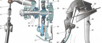
In four-stroke diesel engines, valve timing is used (Fig. 11.1a). The gas distribution bodies are intake and exhaust valves 10 with valve springs 9, and the drive includes valve levers 8 sitting on axles 6 of brackets 7, rods 4, a pusher 5 with rollers 2, cam washers 1 of the camshaft and a drive from the crankshaft to the camshaft . To ensure a tight fit of the valve on the seat, a gap B is provided in the valve drive (during diesel operation, due to heating, the valve stem lengthens and the gap should disappear). If the gap is chosen incorrectly, the valve will be in a slightly open position and gases will pass under the valve; if the gap is large, the valve will open late. To avoid the noted phenomena, it is possible to adjust it using a bolt with lock nut 5. Typically, the recommended clearance value is given in the engine instructions.
When the protrusion of the cam washer 1 runs onto the roller 2 of the pusher 3, the rod 4 moves upward and turns the valve lever 8 relative to the axis 6. In this case, the right end of the lever presses on the valve stem 10 and opens it, compressing the spring 9. When the protrusion of the washer comes out from under the roller pusher, the elastic force of the spring closes the valve. The required valve timing phases (the moments of the beginning of the opening and the end of the closing of the valves) and the laws of valve movement are determined by the profile of the cam washers, their wedge angle, the kinematic diagram of the valve drive and the thermal gap.
The vertical arrangement of the valves in the cylinder cover ensures the least wear on their rods and guide bushings, and opening into the cylinder promotes a tight fit to the seats due to gas pressure. At low pressures in the cylinder, the valve closing tightness depends on the spring tension.
To reduce the inertia forces of the valve actuator, two camshafts (for the intake and exhaust valves) are often installed above the cylinder covers, and the cam washers act directly on the valve stems. However, this complicates the transmission from the crankshaft to the camshafts and clutters the cylinder covers.
In two-stroke diesel engines with direct-flow valve purge, valve-slot gas distribution is used. To admit air into the cylinder, there are purge windows in the sleeve, which are opened and closed by the piston, and the valve mechanism controls the release of gases.
In older two-stroke engines, as well as in 4-stroke internal combustion engines, the valve is actuated by a cam plate via a pushrod, a rod and a valve lever. New designs use a hydraulic drive.
In two-stroke diesel engines with contour and direct-flow slot scavenging, slotted (valveless) gas distribution is used. The gas distribution organs are purge and exhaust windows in the bushing and a piston that performs the functions of a spool. In some early-built diesel engines, the purge windows are blocked by automatic plate purge valves, and the exhaust windows are blocked by rotating flaps (Sulzer diesel engines of the RD type).
Operating conditions of the valve mechanism
Mechanical loads are caused by gas pressure forces Pg on the valve plate 11 (see Fig. 11.1a), inertia forces of moving parts Pj, elasticity of valve springs (10) Pn and force from the pusher rod (3) Pm, which is the normal component of the force pressure of the fist (1) on the pusher.
When the valve begins to open, its speed increases from zero to maximum. The inertial forces of the valve mechanism are directed in the direction opposite to the movement of the pushrod (towards the camshaft), and will press the pusher roller (2) against the cam washer (1). By the time the valve is fully opened, its speed decreases from maximum to zero, inertial forces have the opposite direction (from the camshaft) and tend to tear the pusher roller away from the cam washer, but this is prevented by the valve springs. During the valve closing period, the actions of inertia forces and valve springs will be similar. The separation of the pusher roller from the cam washer leads to damage to their working surfaces, impacts in the valve mechanism, breaking of the valve and seat chamfers, and disruption of the valve timing. Therefore, the elastic force of the springs must always be greater than the inertia forces of the valve mechanism.
Valve springs experience alternating loads, and their material experiences fatigue. During operation of the spring, its temperature increases by 40-50°C, and if the frequency of its own oscillations coincides with the frequency of the disturbing force, a resonance may occur, leading to its breakdown. Valve springs are made with different directions of coils to prevent the coils of one spring from getting between the coils of another in the event of a breakdown of one of them.
Installing several springs on one valve (two, three or four) eliminates their resonance; each spring has its own period of oscillation and when one of them hits resonance, the others act as vibration dampers. When installing several springs at the same time, their sizes are reduced, the stresses in the coils are reduced, the frequency of natural oscillations and the stability of the springs during operation increase, and the reliability of the valve operation increases.
To reduce the amplitude of natural vibrations of springs, an uneven winding pitch, vibration dampers in the form of plate springs, and conical springs are used.
To form an annular supporting surface, the end (support) coils of the spring are brought together until they touch and ground along a plane perpendicular to the axis of the spring.
To ensure the necessary rigidity and strength with as little weight as possible, valve levers 8 (see Fig. 11.1a) are made by forging or stamping and given a T-beam or I-beam shape, and rods 4 are made in the form of steel pipes with tips of various designs.
High thermal loads of gas distribution valves are also caused by contact with hot gases. The most stressed part is the exhaust valve. It perceives heat through the plate plane from the gases in the cylinder (about 80%) and through the transition surface from the plate to the rod from the exhaust gases (15%).
Heat is removed in two ways: from plate 1 (Fig. 11.16) to seat 2 and then into the cooling water; through the rod to guide 5 and then into the mass of metal and into the cooling water.
The temperature of the intake valve plate can reach 300-400°C, and the exhaust valve - 550-800°C. The intake valves have a lower temperature because they are cooled by air during the filling process; The exhaust valve plate is washed with hot gases during the release period. High temperatures deteriorate the mechanical properties of the material, cause high-temperature corrosion, erosion, warping and loose fit of the valve to the seat, increase the risk of the valve stem sticking in the guide, and sometimes lead to burnout of the valve plate.
The following basic requirements are imposed on the design of parts of the gas distribution mechanism:
- gas distribution valves should have the largest possible flow sections (to improve the cleaning of the cylinder from gases and fill it with air), lower temperatures and mass (to reduce inertial forces);
- the valve material must be heat-resistant, wear-resistant, viscous and must not be hardened in air (to prevent the formation of hardening cracks);
- valve springs must be sufficiently elastic and have high fatigue strength;
- valve levers, rods and pushers must be rigid, durable with as little mass as possible (to reduce inertial forces).
Material:
- intake valves - alloy or carbon steel;
- exhaust valves - high-alloy steel.
In forced diesel engines, to increase wear resistance and corrosion resistance, the chamfer of the valve plate (sometimes the seat) is coated with stellite or the exhaust valves are made of nichrome, and the valve stem is nitrided; valve seats - alloy or carbon steel or heavy-duty cast iron;
- springs - high carbon steel;
- camshafts - alloy or carbon steel;
- Knuckle washers are alloy steel.
To increase surface hardness, washers are cemented and hardened.
Valve designs
The valves are installed directly into the cylinder cover, which makes it possible to increase the flow areas for air and gases, but this requires dismantling the cover for inspection and lapping of the valves. In four-stroke diesel engines, the release of gases is always ensured by the pushing stroke of the piston. Therefore, to improve the filling of the cylinder with air, the diameter of the intake valve is sometimes increased (by approximately 20%) by reducing the diameter of the exhaust.
In four-stroke diesel engines, two or four gas distribution valves are usually used, and in two-stroke MODs, one valve is used. An increase in the number of valves complicates the design of the cylinder cover, but reduces their mechanical and thermal stress by reducing the diameter and weight.
A valve without a body (see Fig. 11.1a) consists of a rod 10 and a plate with a conical working chamfer. Most often, valves with a chamfer angle of 45° are used, which provides greater rigidity of the valve and its tight fit on the seat, better self-centering during operation and during grinding, better heat removal from the plate, as well as the most favorable shape of the gas flow when the valve is fully open.
The chamfer of the plate is pressed against the seat machined in the cylinder cover (see Fig. 11.1a), or against a removable seat 2 (see Fig. 11.16), fixed in the cover with a spring ring 3 or other methods (pressing, flaring, caulking). The chamfer and seat are thoroughly ground. The valve stem moves in the guide sleeve 5. The valve is pressed against the seat by springs 9, resting on the lower and upper 7 and 11 plates. The upper plate is attached with conical half rings (“crackers”) on the conical neck of the valve stem (other methods of attaching the upper plate are also used). To prevent the end of the rod from breaking, a hardened cracker is inserted into it or a cap is placed on it.
In modern engines, they began to use seats, the working surface of which is given a W-shape with a pocket 1, in which air is accumulated, preventing the leakage of hot gases into the contact area with the valve plate.
Valves with a body (see Fig. 11.3) are structurally more complex, have a smaller flow area, but are more convenient to operate, since they can be inspected, ground in and replaced without dismantling the cylinder cover.
Due to the presence of a thermal gap in the valve actuator, its movement begins and ends with an impact, causing additional stress in the seat and disc, spring and on the contact surfaces of the valve mechanism. To ensure shock-free operation and reduce noise in the MOD with direct-flow valve purge, a hydraulic valve drive is used. The hydraulic drive also helps to reduce the mass of moving parts and the inertia forces of the valve drive, increasing the reliability of operation.
In the design under consideration (Fig. 11.3), the mechanical valve drive is replaced with a hydraulic one. For this purpose, a piston 6 is placed on the valve stem, which is pressed by oil supplied through channel 7 from a hydraulic piston amplifier, which is driven by a cam mounted on the camshaft. Valve springs in the new design are eliminated, and their function is performed by an “air spring” with piston 5. When the oil pressure in the valve drive decreases, it returns to the seat by an air spring, in which compressed air from below presses on piston 5 and the valve rises and gently sits on seat, which significantly reduces the hardening of the seating surfaces.
Reducing the thermal stress of the valves is achieved by intensive cooling of the cylinder cover in the area of the seat and the seat itself.
Modern powerful MODs and SODs often provide for automatic rotation of the valves relative to the axis during diesel operation. Rotation of the valves ensures a more uniform temperature distribution in the plate and less deformation, uniform wear of the plate and seat and some self-grinding. This is most simply achieved by installing special blades on the lower part of the rod 3, which rotate together with the valve under the action of the gas flow.
In some cases, a special device (“rotocap”) is used to force the valves to rotate. Rotating the valves during operation ensures a more uniform distribution of plate temperatures and increases its service life (Fig. 11.4).
Camshaft
Knuckle washers located on the camshaft serve to control the opening and closing of gas distribution valves, as well as to drive high-pressure fuel pumps, a fuel priming pump, and a starting system air distributor.
The camshaft is made one-piece or composite (to simplify manufacturing and installation) and is mounted on split bearings. To prevent axial movement, the shaft is usually fixed in a thrust bearing.
Knuckle washers in VOD are usually forged integrally with the camshaft, while in SOD and MOD they are made removable (one-piece or split). Removable washers 1 (Fig. 11.5a) of the gas distribution valve drive are usually made one-piece and secured to the shaft with keys 2 or on a hydraulic press fit, and washers of the injection pump drive are most often detachable and secured in various ways, allowing you to change their wedge angle relative to the camshaft.
The cam washer of the Burmeister and Wein diesel injection pump has a symmetrical profile (Fig. 11.5b) and consists of two halves. One of them has grooves into which the protrusions of the other half fit, which makes it possible to adjust the advance of the fuel supply independently in forward and reverse.
On the camshaft 2, on the key 3, a sleeve 4 is installed, which has an annular groove with an internal cone, to which the cam washer 5 is pressed using bolts. In the latest diesel models, a composite washer with a negative profile is used (Fig. 11.6d).
For MAN diesel engines, the cam washer (Fig. 11.5c) has an asymmetrical profile and consists of two halves: the occipital 1, sitting on the shaft 3 on a key 2, and the profile cam washer 5, which can be rotated to a certain angle using bolts 4.
For Sulzer diesel engines, washer 2 (Fig. 11.5e) has a symmetrical profile and also consists of two halves. The washer sits loosely on the sleeve 1, fixed on the camshaft 5 with a key 4 and a pin 6. The sleeve has a thread at the end onto which a nut 3 is screwed; the end surfaces of the nut, bushing flange and washers are conical.
In four-stroke reversible diesel engines, two sets of cam washers are installed - one for forward, the other for reverse, and in two-stroke diesel engines with direct-flow valve scavenging - one (if reversing is carried out by turning the camshaft at a certain angle) or two sets (if reversing is carried out by an axial shift camshaft).
The camshaft is driven from the crankshaft.
The design of the drive depends on the location of the camshaft: with an upper location (above the cylinder covers), characteristic of a VOD, a roller drive with bevel or helical gears is used; at the bottom and middle - gear drive.
To reduce the size of gears, drives are made with intermediate gears (Fig. 11.6a). The intermediate gear 3 is in mesh with the drive gear 4 of the crankshaft and with the driven gear 2 of the camshaft.
Since in a four-stroke diesel engine the camshaft speed must be half the crankshaft speed, gear 2 has twice the diameter of gear 4 (idler gear 3 has no effect on the gear ratio). The shaft of the speed controller 1 is also driven from gear 2.
A chain drive (Fig. 11.66) is used when there is a large distance between the axes of the crankshaft and camshaft, when a gear drive would be cumbersome and expensive.
The drive sprocket 7 of the crankshaft is connected to the camshaft sprocket 1 by three single chains 6. Sprocket 5 is a guide and is used to drive the air distributor, lubricators and speed controller. Sprocket 2, fixed in bracket 3, serves to tension the chain. Tension is carried out by turning bracket 3 around axis 9 counterclockwise. Rod 4, loaded with a powerful spring, transmits force to bracket 3. The chains move along steel guide rails 8, lined with rubber, which prevents lateral vibrations of the chains. The axles of all sprockets and chains are lubricated with oil.
New MOD designs use hydraulic chain tensioners (see Fig. 11.7). The chains are lubricated by oil supplied to them through nozzles.
Damage to valves
In the gas distribution mechanism, the most vulnerable element is the intake and exhaust valves, which experience high mechanical and thermal loads. The greatest danger is posed by thermal loads determined by the operating conditions of the valves in the zone of high temperatures of the gases surrounding them. Exhaust valves have the highest temperatures. To improve valve performance, engine builders strive not to go beyond 500-520°C.
Causes of damage.
- When temperatures exceed 650°C, the valve material loses its strength properties, and at the same time unfavorable conditions are created for the occurrence of high-temperature corrosion.
- Frequently repeated changes in temperatures from high to low provoke the occurrence of thermal fatigue cracks in the areas of transition of the valve plate to the stem or in the area of the grooves for the cracks.
- The appearance of deeply penetrating oxidation and scaling on the valve body; Tarnished colors on the valve stem indicate high temperature oxidation due to heating of the stem in its guide sleeve.
- When temperatures exceed the creep limit, the valve disc deforms and takes on the shape of a bowl. With minor deformations, the tightness of the fit is disrupted, and with more serious ones, the plate may break.
- Breakage of the plates is also possible when the valve timing is disrupted and the valve hits the piston. More serious damage occurs when the engine is torn apart, crackers jump out of the valve plate, the valve falls down and gets under the piston. The valve breaks through the fire bottom of the cylinder cover, water penetrates into the combustion chamber, and a hydraulic shock occurs in the cylinder, accompanied by bending of the connecting rod and other damage.
Loss of valve tightness occurs for a number of reasons, including:
- erosive wear of the seat cone of the valve disc and its seat, lack of rotation;
- deposits of coke and ash on the plate;
- valve deformation;
- violation of the alignment of the valve axis in the guide;
- burnout of the seating surface due to high-temperature corrosion caused by the presence of vanadium and sodium in the fuel;
- low temperature corrosion caused by high fuel sulfur content and low valve temperatures (intake valves).
Low-temperature corrosion mainly affects intake valves that have a lower temperature, and therefore vapors of water and sulfuric acid formed during the combustion of sulfurous fuel condense on them, especially in the area of the rods. Characteristic signs: the presence of pitting ulcers on the rods and working cones of seats and valves, roughness and darkening of surfaces.
Practical recommendations.
1. It is recommended, if possible, to avoid using fuels with a high vanadium content in engines (it is advisable that its content does not exceed 100... 150 ppm).
2. Avoid flooding the fuel with sea water; in case of accidental ingress of water, carry out active separation by washing the fuel with hot fresh water supplied to the fuel stream in front of the separator. Water, mixing with fuel, dissolves the sodium compounds contained in it and is removed along with them during separation. Reducing the content of Na2SO4 in a mixture with V2O5 promotes an increase in the melting point, prevents sticking to the valve body, and therefore reduces the likelihood of corrosion of the latter.
3. It is necessary to take measures aimed at reducing the temperature of the exhaust valves (the latter should not exceed 530°C, the desired level is not higher than 450°). In many ways, the adoption of these measures is a matter of concern for the engine designer. However, a ship mechanic forced to use fuel with a high vanadium content can partly correct the situation by lowering the temperature of the valves by reducing the engine load.
It is important to note that the use of stellite surfacing, the manufacture of a plate or the entire valve from nimonic, and the use of rotocap devices (valve turning mechanism) increase the service life of the valves, but in general they do not solve the problem outlined here.
4. When using fuels with a high vanadium content, it is useful to add additives that include Mg (Ameroid Mark-4, Vecom Fot-SA, etc.). During fuel combustion, magnesium is oxidized to form MgO, the melting point of which is 2800°C. The products of its interaction with vanadium oxides already have a melting point of 800-900°C, which significantly exceeds the temperature of the valves and thereby eliminates the risk of adhesion and deposition of aggressive compounds on valves, turbine blades and recovery boilers. As a result, vanadium compounds leave the diesel engine in dry form along with combustion products. Experience shows that these additives are quite effective in combating high temperature corrosion and extending the life of exhaust valves.
Literature
Marine internal combustion engines - Voznitsky I.V. Punda A.S. [2010]
- Purge systems for two-stroke engines
- Duty cycles of two-stroke engines
- Operating cycles of four-stroke engines
- Basic engine data: cylinder displacement
- Classification and marking of engines
Pros and cons of belt drive
The belt drive gained its popularity due to its advantages compared to similar types of drives.
- Despite the fact that the production of such structures is more complicated than chain ones, they are much cheaper.
- It does not require constant lubrication, due to which the drive was placed on the outside of the power unit. As a result, replacing and diagnosing the timing belt has become much easier.
- Since in a belt drive the metal parts do not interact with each other, as in a chain drive, the noise level during its operation has decreased significantly.
Despite the large number of advantages, the belt drive also has its disadvantages. The service life of a belt is several times lower than that of a chain, which causes its frequent replacement. If the belt breaks, it is likely that the entire engine will have to be repaired.
What is the purpose of the belt?
The timing belt is a part whose purpose is to act as a connecting link.
Thanks to the timing belt, the camshaft and crankshaft work synchronously, which contributes to the proper functioning of the engine as a whole. This is the need for using a strap.
Markings on the strap
Let's look at a few examples of translating the timing belt decoding:
- ISO-58111x19. The first two numbers (58) encrypt a series of teeth used on the product. In this case, the pitch and profile will be without a groove, the shape will be semicircular, and the height will be 3.5 mm. Then there are three numbers (111), which indicate the number of teeth. By number 19 you can determine the width of the product. There are belts on sale whose teeth are made in the form of a rounded trapezoid.
- 58127x3/4 HSN. Here the first two digits also indicate a series of teeth. The numbers 127 indicate their number, but you need to take into account that in straps belonging to the 40 series, this number is conditional. The numbers 3/4 indicate the width of the product in inches. In this case it is also 19 mm. The HSN mark at the very end indicates that the product is made of durable, highly saturated nitrile. This material has proven its strength. If there are no such letters at the end, then the strap is made of neoprene rubber.
Table: Belt markings
Manufacturers may label their products differently. The table shows how to decipher the timing values.
After how many km should the timing belt be changed?
The cause of the engine stopping may be a broken belt. Therefore, it is advisable to find out in advance on which engines the valves bend. It is necessary to change the belt every 60-70 thousand km. But, unfortunately, many drivers do not have time to replace the timing belt. On machines with 16-valve engines, a broken belt will not harm the valves, but on 8-valve engines, deformation of the valve occurs, which is called “valve bent.” But on 8-valve engines, the valves may also not bend if the engine is bored out, special recesses are machined on the pistons, designed specifically for the size of the non-raised valve.
General diagram and interaction of parts
The timely opening of the intake and exhaust valves in the cylinders of an internal combustion engine is ensured by the operation of the gas distribution mechanism or timing mechanism.
This device consists of a camshaft with cams, the required number of rocker arms or valve lifters, springs and the valves themselves. The camshaft gear, belt or chain used to transmit rotation from the crankshaft, and the chain tensioning mechanism are also part of the timing belt.
- Fuel injection phase. The piston begins to move from top dead center to bottom. The fuel supply valve opens, and the fuel-air mixture fills the rarefied space of the cylinder. Having measured the required dose of fuel assembly, the valve closes. The crankshaft has rotated 180 degrees from its original position.
- Compression phase. Having reached bottom dead center, the piston changes direction of movement to TDC, compressing the fuel-air mixture. When the top dead center is reached, the compression phase of the working fluid ends. The crankshaft rotated 360 degrees.
- Work stroke phase. When the piston is at TDC and the maximum design compression ratio is reached, the fuel-air mixture ignites. Under the influence of rapidly expanding gases, the piston moves to the bottom dead center, making a working stroke. When BDC is reached, the third phase of operation of a four-stroke internal combustion engine is considered completed. The crankshaft rotated 540 degrees.
- Exhaust gas removal phase. Under the action of the crankshaft, the piston begins to move towards top dead center, displacing the combustion products of the fuel-air mixture from the volume of the cylinder through the opened exhaust valve. When the piston reaches TDC, the exhaust phase is considered complete, the crankshaft has rotated 720 degrees.
To achieve such precision in the timing of the opening of the intake and exhaust valves, the gas distribution mechanism is synchronized with the engine crankshaft speed. A belt or chain transmits rotation to the camshaft, the cams of which, pressing on the rocker arms, alternately open the intake and exhaust timing valves.
Low valve engines
The gas distribution mechanism of the internal combustion engine has come a long way from the 1900s to the present day.
Lower valve engines with a camshaft in the cylinder block were used everywhere until the mid-twentieth century. The design and design of the intake and exhaust valves, arranged in a row with the plates facing upward, ensured ease of manufacture and low noise engine. The main disadvantage of this design was the complex path of the fuel-air mixture, non-optimal cylinder filling mode, and, as a result, lower power of the power unit.
A gas distribution mechanism of this type was used until the 90s of the twentieth century in trucks. An example of this is the GAZ 52, the production of which ended in 1991.
Mixed valve arrangement
Attempts to increase the power characteristics of internal combustion engines led to the creation of an engine with a mixed valve arrangement. The intake ones were located in the cylinder head, and the exhaust ones were in the block, like a conventional “lower valve”.
There is one camshaft, also located in the cylinder block. The valves responsible for the intake of the fuel-air mixture were controlled by rods - pushers, through which force was transmitted from the camshaft, the exhaust valves - using the usual rocker arm.
This layout scheme ensured a lower fuel assembly temperature, and, as a result, higher power compared to lower valve internal combustion engines.
Overhead valve engines
The gas distribution mechanism, the intake and exhaust valves of which are located in the cylinder head, and the camshaft is in the block itself, was designed by David Buick at the very beginning of the twentieth century. The valves were controlled by push rods that acted on the rocker arms.
This layout scheme is highly reliable due to the transmission of rotation from the crankshaft to the camshaft using a gear. A toothed belt worn out during operation can break, causing serious damage to the timing valve mechanism, while a worn transmission gear will only slightly shift the valve timing, which an experienced driver will notice by changes in engine operation.
The downside is a certain inertia of such a design, which imposes restrictions on engine speed, and, consequently, on torque and the degree of boost. The use of more than two valves per cylinder leads to a more complex gas distribution mechanism and an increase in the overall dimensions of the engine. Four-valve engines of this configuration are used in KamAZ trucks and diesel locomotive engines.
The gas distribution mechanism of the Volga car of the twenty-first model was designed precisely according to the overhead valve design.
- Engines in which the camshaft and timing valves are located in the cylinder head are designated by the abbreviation SOHC. The operating principle and design of the timing valve control mechanism is very diverse. There is a scheme for opening valves using rocker arms, levers and pushers. This engine design became most widespread in the period from the mid-60s to the end of the 80s of the twentieth century. Currently, such engines are installed in inexpensive passenger cars.
- Engines whose gas distribution mechanism includes two camshafts are designated by the abbreviation DOHC. With two valves per cylinder, each camshaft opens its own bank of valves. Such a timing device makes it possible to reduce the inertia of the crankshaft, and thereby significantly increases the speed and power of the internal combustion engine. The operating principle of an engine using four or more valves per cylinder is no different from that described above. Such power units demonstrate greater power than their two-valve counterparts and are installed on most modern cars.
In engines with this type of gas distribution mechanism, the camshaft drive device plays an important role.
The transmission element is a chain located in a hermetically sealed volume and washed with oil, or a toothed belt located on the outside of the engine. A breakdown of the timing drive often leads to dire consequences. A broken belt, worn out during operation, causes an instant stop of the camshaft, as a result of which some valves remain open. The impact of the piston on the protruding plate causes serious damage to the cylinder head. In especially severe cases, repair is impossible and replacement of this engine element is required.
Principle of operation
The operation of the gas distribution mechanism is difficult to consider separately, in isolation from the engine operating cycle. After all, its main task is to open and close the valves in time for a certain period of time. Accordingly, on the intake stroke, the intake valves open, and on the exhaust stroke, the exhaust valves open. That is, in fact, the mechanism must implement the calculated valve timing.
Technically it happens like this:
- The crankshaft transmits torque through a drive to the camshaft.
- A cam on the camshaft pushes a pushrod or rocker arm.
- The valve moves inside the combustion chamber, allowing access to fresh charge or exhaust gases.
- After the cam goes through the active phase of action, the valve returns to its place under the action of the spring.
It is also worth noting that during a full operating cycle, the camshaft makes 2 revolutions, alternately opening the valves in each cylinder, depending on the order of their operation. That is, for example, with a 1-3-4-2 operating scheme, at the same moment in time, the intake valves will be open in the first cylinder, and the exhaust valves in the fourth. In the second and third the valves will be closed.
There should be no even the slightest damage on the supporting surfaces under the crankshaft journals, and the bearing housings must be free of cracks. After cleaning and washing the camshaft, be sure to check the gap between its journals and the hole in the cylinder head support.
The gas distribution mechanism has 2 inherent problems - loose connection of the valves to the sockets and the inability to fully open the valves.
A loose connection of the valves to the sockets is detected by the following indicators: popping noises that sometimes occur in the intake or exhaust pipes, a decrease in engine power. Factors that cause leaky valve closure may include:
- the appearance of carbon deposits on the surface of valves and seats;
- formation of cavities on working chamfers and curvature of the valve head;
- faulty valve springs.
Incomplete opening of the valves is accompanied by a knocking sound in the engine and a decrease in its power. This breakdown occurs as a result of a significant gap between the valve stem and the toe of the rocker arm. Typical timing failures include wear of camshaft gears, pushers, valve guides, camshaft displacement and wear of bushings and rocker arm axles.
Practice shows that the gas distribution mechanism accounts for approximately a quarter of all engine failures, and preventing these failures and restoring the timing takes 50% of the labor intensity of maintenance and repair work. To diagnose breakdowns, the following parameters are used:
- determine the phases of the gas distribution mechanism of the car;
- measure the thermal gap between the valve and the rocker arm;
- measure the gap between the valve and the seat.
Valve timing measurement
Such diagnostics of the engine timing belt is performed with the engine turned off using a special set of devices, including a pointer, a torque scope, a goniometer and other additional devices. In order to fix the period of opening of the intake valve on the 1st cylinder, it is necessary to rock the rocker arm around its axis, and then direct the engine crankshaft until a gap appears between the valve and the rocker arm. A goniometer for measuring the desired gap is placed directly on the crankshaft pulley.
Measuring the thermal gap between valve and rocker arm
The thermal gap is measured using a set of probes or another special device. This is a set of metal plates 100 mm long, the thickness of which must be no more than 0.5 mm. The engine crankshaft is turned up to the upper limit point, during the compression stroke of the cylinder selected for control. Directly thanks to probes of different thicknesses, alternately inserted into the formed hole, the gap is measured.
Determining the gap between valve and seat
The gas distribution mechanism of the internal combustion engine has come a long way from the 1900s to the present day.
Design of a desmodromic gas distribution mechanism
For engines whose timing design allows the use of springs to close the valves, there is a limitation on the maximum number of revolutions per minute. When the value reaches 9000 rpm, the springs will not be able to provide the required response speed, which will inevitably lead to engine failure.
The principle of desmodromic timing is to use two camshafts, one of which opens and the second closes the valves. In such an engine there is no limit on the speed developed, because the speed of operation of the mechanism directly depends on the speed of rotation of the crankshaft.
The creation of a gas distribution mechanism with variable phases became possible relatively recently, with the beginning of the use of on-board computers and electronic control units in engine construction. The system of electromagnetic valves, which changes the operating mode according to microprocessor commands, allows you to extract power from the engine that is close to the design one, with minimal fuel consumption.
Valve mechanism
The design of the valve mechanism includes valve seats, guide bushings, valve rotation mechanism and other elements. The force from the camshaft is transmitted to the rod or to an intermediate link - the valve rocker arm, or rocker.
You can often find timing models that require constant adjustment. Such designs have special washers and bolts, the rotation of which sets the required clearances. Sometimes the gaps are maintained automatically: their position is adjusted using hydraulic compensators.
Valve system operation
Each valve is equipped with a spring that returns it to the upper (closed) position. A special cam located on the shaft, rotating, presses on the valve, opening it at the right moment. To prevent the spring from slipping, an annular groove is made on the top of the valve, sometimes two or three, a cracker is inserted into it, to which a plate with a cone-shaped hole is attached. The cracker, assembled from two parts, also has a conical surface and securely holds the plate with the spring. The valve assembled in this way is called “dried.”
Timing drives
Depending on the design features of the car engine and the gas distribution mechanism, in particular, the number of drives and their type may vary.
- Chain drive. A few years ago, this drive was the most common, but is still used in the timing belt of diesel engines. With this design, the camshaft is located in the cylinder head and is driven by a chain leading from the gear. The disadvantage of such a drive is the complex process of replacing the belt, since it is located inside the engine in order to ensure constant lubrication.
- Gear drive. Installed on engines of tractors and some cars. Very reliable, but extremely difficult to maintain. The camshaft of such a mechanism is located below the cylinder block, due to which the camshaft gear clings to the crankshaft gear. If a timing drive of this type became unusable, the engine was almost completely replaced.
- Belt drive. The most popular type, installed on gasoline power units in passenger cars.
Timing mechanism design
The engine gas distribution mechanism drives the valve system. Different car models use different technical solutions to ensure the operation of the timing belt, but the principle of operation is the same for all and the usual gas distribution mechanism consists of:
- camshaft with cams installed on it;
- systems of intake and exhaust valves with discs secured with crackers;
- levers (rockers) or hydraulic compensators;
- camshaft gears;
- crankshaft gears;
- timing belt or chain;
- additional gears and rollers.
The valves are designed to ensure the supply of fuel assemblies to the engine cylinders and the removal of exhaust gases.
Control of gas distribution stages
Modern engine models have undergone significant changes, having received new control systems based on microprocessors - the so-called ECUs. In the field of engine building, the main task was not only to increase power, but also to ensure the efficiency of produced power units.
It was possible to increase engine performance while reducing fuel consumption only with the use of timing control systems. An engine with such systems not only consumes less fuel, but also does not lose power, which is why they have become widely used in automobile production.
The principle of operation of such systems is that they control the rotation speed of the timing camshaft. Essentially, the valves open a little earlier by turning the camshaft in the direction of rotation. Actually, in modern engines the camshaft no longer rotates relative to the crankshaft at a constant speed.
The main task remains the most efficient filling of the engine cylinders, depending on the selected operating mode. Such systems monitor the condition of the engine and adjust the supply of the fuel mixture: for example, when idling, its volumes are reduced to almost a minimum, since fuel is not required in large quantities.
Camshaft
The cams pressing on the valves are made to move by a special mechanism - the timing drive, or rather another of its components - the gas distribution shaft, which is also called the camshaft. The cams are its integral part, and it is mounted on special support journals in the cylinder head. Depending on the location of the cams on the camshaft, the valves necessary for normal engine operation open one by one, which is the principle of operation of the timing belt. Some engine models, where the cylinders are not in line, have a pair of camshafts.
Operation of the timing shaft system
The camshaft is driven by a crankshaft, at the end of which there is a gear of a specially selected diameter. Another gear is installed on the camshaft. The transmission of torque from the crankshaft to the camshaft is transmitted by a steel chain or a belt with teeth for the gears, which is made of durable reinforced rubber. The operation of the timing mechanism depends on the correct installation of the chain or belt. In this case, all valves open at the right moment, which allows the air-fuel mixture to enter the cylinder, burn there and remove exhaust gases. This is the main principle of operation of the gas distribution mechanism.
Depending on the design, the valve is pressed directly by the cam on the camshaft or through a lever called a rocker, which is acted upon by the cam. The purpose and design of the gas distribution mechanism allows the necessary valves to be opened at the moment the desired engine stroke occurs, which ensures its uninterrupted operation. Any violation leads to malfunction, including breakdown of the power unit.
Valve group design:
2.1. Valve arrangement:
Engine valves consist of a stem and a head. The heads are most often made flat, convex or bell-shaped. The head has a small cylindrical belt (about 2 mm) and a sealing chamfer at an angle of 45˚ or 30˚. The cylindrical tape allows, on the one hand, to maintain the main diameter of the valve when grinding the sealing chamfer, and on the other hand, to increase the rigidity of the valve and thereby prevent deformation. The most common valves are those with a flat head and a sealing chamfer at an angle of 45˚ (these are most often intake valves), and to improve filling and cleaning of the cylinders, the intake valve has a larger diameter than the exhaust valve. Exhaust valves are often made with a bulbous, ball-shaped head.
This improves the flow of exhaust gases from the cylinders, and also increases the strength and rigidity of the valve. To improve the conditions for heat removal from the valve head and increase the overall non-deformability of the valve, the transition between the head and the stem is made at an angle of 10˚ - 30˚ and with a large radius of curvature. At the upper end of the valve stem, grooves of conical, cylindrical or special shape are made, depending on the adopted method of attaching the spring to the valve. Sodium cooling is used in a number of engines to reduce the thermal load on burst valves. To do this, the valve is made hollow, and the resulting cavity is half filled with sodium, the melting point of which is 100˚C. When the engine is running, sodium melts and moves through the valve cavity, transferring heat from the hot head to the coolant rod, and from there to the valve actuator.