Many owners of a VAZ 2107 with a contactless ignition system are interested in the question of how to check the Hall sensor. The question is, in fact, quite relevant, since if the device fails, starting the engine becomes problematic or completely impossible. Therefore, it is important to know what actions to take to fix the problem and how to replace the sensor.
- Purpose of the sensor
- Operating principle of the device
Video: Hall sensor operation
- Signs of a malfunction of the Hall sensor on a VAZ 2107
- How to check the sensor
Video: checking the sensor with a multimeter
- Video: how to replace the Hall sensor on VAZ family cars
Signs of sensor malfunction
Hall sensor Malfunctions in the Hall sensor manifest themselves in different ways. Even an experienced technician will not always immediately identify the cause of engine problems. Here are some of the most common symptoms:
- The engine starts poorly or does not start at all.
- At idle, the engine runs rough and jerky.
- The car may jerk when driving at high speeds.
- The power unit stalls while driving.
If one of these signs appears, you must first check the serviceability of the Hall sensor. Also, do not exclude other malfunctions of the ignition system found in cars.
Signs of sensor malfunction.
Reasons for failure of diesel generators
Below are the most common factors for Hall sensor failure:
- Presence of contamination. A common cause of breakdown is simple dirt. When it appears, the controller will signal this - the car begins to act up.
- The spark is gone. It is necessary to check the wiring and terminals for the presence and quality of contact. Oxidation of at least one of the three terminals can lead to a circuit break. In addition, a simple bend or break in the wire may occur - this may be caused by the displacement of the DC pad by the vacuum ignition corrector. To avoid this, the wiring must be secured so that when displaced it bends into a loop.
- Wiring failure. If the high-voltage wiring in the car is heavily worn out, if it runs close to the sensor wires, there is a possibility of a high-voltage breakdown. This often happens when the air humidity is high or when you accidentally drive into a deep puddle.
It is better to place the wires from the sensor away from the rest of the car's wiring. You can also avoid this problem by regularly replacing all electrical wiring once every two to three years. In addition, the sensor may fail due to overcharging of the battery generator if the controller received an excessive load and any element burned out at the switch contact.
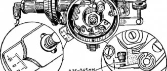
How to check the Hall sensor
It is recommended to carry out the test using a simple device that every driver can do with his own hands. He will need a resistance of 1 kOhm and a simple LED. A resistance is soldered to its leg, two pieces of any length of flexible wire convenient for operation are soldered to it, and the device is ready. Checking the Hall sensor is preceded by determining the presence of power supply to it:
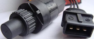
- the distributor cap is removed;
- the plug box from the distributor is disconnected;
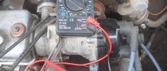
- the tester is connected to terminals 1 and 3, then the ignition is turned on.
If the car's electrical wiring is functioning normally, the tester will show a voltage of 10 volts or higher. After this, we connect the designed device to the same terminals - the LED lights up if the polarity has been chosen correctly. Otherwise, you need to swap the ends of the wires. The subsequent verification scheme is as follows:
- We do not touch the wire connected to the 1st terminal, but we transfer the end from the 3rd to the free 2nd terminal;
- rotate (manually or with a starter) the camshaft.
If you notice that the LED blinks during this process, then the ignition sensor does not need to be replaced. It is also possible to check the Hall sensor with a multimeter. It is connected to the ignition output contact, setting the device to voltmeter mode. The device arrow should move in the range of 0.4-3 Volts (an indicator of the health of the sensor).
How to check the Hall sensor
Malfunctions of the Hall sensor manifest themselves in different ways; even experienced specialists are not able to accurately determine the failure. There are a number of symptoms, but they indicate problems with the sensor indirectly, because These signs happen for different reasons:
- the engine does not start;
- at idle speed fluctuates;
- while driving, when the speed increases, the car jerks;
- The engine stalls for no reason.
If such symptoms occur, it is necessary to also check the Hall sensor. In addition to the method indicated in the article, there are several more. For example, the simplest thing is to ask someone for a working sensor and simply replace it on your car; if the problems go away on their own, then the sensor is faulty.
Material on the topic: what is an electrical circuit.
If you have a multimeter at hand, checking is easier than ever. To do this, you need to set the voltage measurement game mode on the device and test the indicators at the output of the sensor; if it is working properly, the voltage will vary from 0.4 to 11 V. Another common method involves checking in the absence of sparking (if there is power in the ignition system) and consists of in sensor simulation. The block is removed from the distributor and the ignition is turned on. Next, using a piece of wire, contacts 3 and 2 on the block are closed; if a spark appears on the central channel of the ignition coil, it means that the Hall sensor is faulty and requires replacement.
It will be interesting➡ USB pinout: types of connectors and cable color assignments
Another way is to check the existence of resistance on the sensor. To do this, you need to build a simple device, which consists of a 1 Kom resistor, a light diode, and flexible wiring. Solder a resistance to the leg of the light diode, and to it two wires of such length that it is convenient for operation (not short). Then remove the distributor cap, disconnect the distributor and the plug box. Then we check whether the electrical circuit is working properly. Therefore, we connect the electronics multimeter to the first and third terminals, then turn on the car’s ignition.
Under good conditions, the measurement on the device’s screen should be within 10-12 V. Then also connect the made mechanism to the same terminals. If you did everything correctly, the light diode will light up. Otherwise, you need to change the wiring places. Next you need to do this: do not touch the wire that is connected to the first terminal, do not touch the tip from the third terminal, transfer it to the free second terminal, turn the camshaft (by hand or with a starter). If the diode blinks when turning the shaft, this indicates that the sensor should not be changed.
Replacing the Hall sensor.
Checking the sensor with a multimeter
You can check the DH in different ways. One popular diagnostic option is a multimeter or voltmeter. This verification method has two options. Let's look at how to check a car's hall sensor in both cases.
1st method
To carry out diagnostics, you need to find a working voltmeter or multimeter that is set to measure DC voltage (direct current) in the range of 20 Volts. In addition, you will need to stock up on 2 iron pins, through which the DC will be checked. Before checking the hall sensor, you will need to remove the rubber boot from the block, which is connected to the distributor and directly to the DH.
Let's continue:
- remove the main armored wire from the distributor;
- We connect it to the arrester or to ground.
This is done in order to exclude the accidental occurrence of a discharge, because this may contribute to starting the engine during the test.
Checking the digital Hall sensor.
Further:
- turn on the ignition;
- remove the block from the distributor;
- set the mode on the multimeter to DC 20 V;
- We connect the negative terminal of the device to ground (any part of the car body);
- the positive probe of the device will serve as a voltage meter.
The block going to the distributor has three wires: red, green and white (colors may be different). On the red wire, the voltage of the device should show 11.37 or close to 12 V. On the green or middle wire, the value is also close to 12 V. And finally, on the last - white wire, the value is 0.
Checking the Hall sensor with a tester.
By the way, if you put the device in the audio test mode, then placing the probe on the contact, you will hear a constant ringing, which will indicate that the white wire is connected to ground. That's how it should be. What did the preliminary check give? We made sure that the households received all the necessary impulses. Continue (multimeter in DC measurement mode):
- We take the prepared pins (studs) and thread them like this: one into the green (middle wire), the other into the white (ground wire);
- We connect the block in its place, in the car distributor.
Why are pins needed? They play the role of a current conductor. There are no contacts on the back of the block, and the values can only be checked if the wires are exposed. This is not recommended, which is why the pins are inserted. Go ahead:
- take the multimeter clamps (ignition is on);
- We connect the positive terminal of the multimeter to the pin of the middle wire of the block, and the negative terminal to the other (white wire).
It will be interesting➡ Options for connecting circuits for pass-through switches
In this position, the multimeter value should be within 11.2 V. Next:
- crank the crankshaft while simultaneously observing the instrument readings;
- if the instrument readings drop to 0.02 V (lower measurement limit) and rise to 11.8 V (upper measurement limit) when cranking the crankshaft, then this is considered normal.
Attention. The DC is considered to be in good working order if, when cranking the crankshaft, the upper measurement limit is no less than 9 V, and the lower limit is no more than 0.4 V. Thanks to these measurements, we checked the performance of the DC installed in the car distributor.
Material on the topic: how to determine current power.
2nd method
The second verification method differs from the first in that this time the DH is diagnosed autonomously. In other words, it will not be connected to the ignition system - to the switch. So, to carry out this method you will need a homemade assembly of 3 contacts inserted into the distributor block, plus/minus pins and 2 test points for measurements. The homemade assembly diagram will look like this
Here's what to do:
- Connect the three homemade contacts to the connectors where the original distributor block is inserted (if the sensor is removed, then to its terminals);
- supply plus/minus power to the homemade assembly;
- connect the plus of the multimeter to one control point for measurement, the minus to the other;
- turn the crankshaft.
Again, the upper limit of measurements on a working sensor should not be lower than 9 V, and the lower limit should not be higher than 0.4 V. If the DC is removed from the car, then it will be checked as follows:
- the sensor leads are connected to the homemade assembly (the other connections are the same as in the case described above);
- take a knife or curtain and draw the blade along the slot in the DH.
When the curtain is closed, the DC readings are above 9 V, when open – below 0.4 V. Thus, using a multimeter, you can check the DC for serviceability in 2 simple ways. Of course, there are many other options for checking the sensor, but they are more difficult to carry out, although they provide instant access to the DH. A general familiarity with the operating principle of DCs, despite the gradual displacement of contactless ignition systems by multiprocessor ones, will provide many benefits in the future. So, this can help the car owner when using other car sensors that operate on the Hall principle: speed sensor, camshaft position, etc.
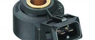
Various models of Hall sensors.
Types and scope of application
Despite the variety of elements that use the Hall effect, they can be divided into two types:
- Analogue, using the principle of converting magnetic induction into voltage. That is, the polarity and voltage directly depend on the characteristics of the magnetic field. Currently, this type of devices is mainly used in measuring technology (for example, as current, vibration, rotation angle sensors). Hall effect current sensors can measure both AC and DC current
- Digital. Unlike the previous type, the sensor has only two stable positions, indicating the presence or absence of a magnetic field. That is, operation occurs when the intensity of the magnetic field has reached a certain value. It is this type of device that is used in automotive technology as a sensor for speed, phase, camshaft position, as well as crankshaft, etc.
It should be noted that the digital type includes the following subtypes:
- unipolar - triggering occurs at a certain field strength, and after it decreases, the sensor returns to its original state;
- bipolar - this type reacts to the polarity of the magnetic field, that is, one pole turns the device on, and the opposite pole turns it off.
Example of using an analog element
Let us consider, as an example, the design of a current sensor whose operation is based on the Hall effect.
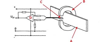
Simplified circuit of a current sensor based on the Hall effect
Designations:
- A is a conductor.
- B – open magnetic conductor ring.
- C – analog Hall sensor.
- D – signal amplifier.
The operating principle of such a device is quite simple: the current passing through the conductor creates an electromagnetic field, the sensor measures its magnitude and polarity and produces a proportional voltage UDT, which is supplied to the amplifier and then to the indicator.
How to check the Hall sensor in the distributor?
A common way to check is to simulate the presence of a sensor. This is the most effective way. It is suitable when there is electricity in the ignition system components and in the complete absence of a spark. To check from the distributor, we remove the block for connecting the plugs. Then we activate the ignition of the car and, using small pieces of wire, close outputs 2 and 3. If there is a spark on the middle wire of the ignition coil, it means that the sensor has died. To detect the formation of a spark, we place the high-voltage wiring next to the ground. There are several verification methods:
Interesting on the topic: How to check a zener diode.
Ring with a multimeter
It is necessary to measure the voltage that is generated at the output of the controller. If the device is working properly, the voltage will be within 20 volts. First of all, you will have to remove the cover from the block connected to the distributor. Next we proceed like this:
- dismantle the main shielded wire from the distributor;
- connect it to ground (to prevent the risk of accidental discharge);
- activate the ignition;
- remove the distribution block;
- set the multimeter to the DC 20 V position;
- We connect the negative probe to ground;
- We will need the positive one to measure the voltage.
There are 3 multi-colored wires on the distributor block. On red, the voltage should be around 12 V. The same value is the norm for the green wire. But on white it should be zero.
Hall Sensor.
If the device is in sound mode, a ringing sound will appear when the probe touches the white wire. This is evidence of a normal connection of the wire to ground. This is how we made sure that all impulses were present on the DH. Now we take small nails prepared in advance and insert them: one into the green (middle) wire, the other into the white (ground). We mount the block into the distributor.
It will be interesting➡ How to test a capacitor using a multimeter
Carnations act as conductors. The fact is that on the other side of the block there is no contact base, and the wiring cannot be exposed. We bring the positive probe to the middle wire, the minus probe to ground. The device should show 11.2 V (approximate value). We turn the crankshaft. If at the lower point the readings correspond to 0.02 V, and at the upper point 11.8 V, this is normal.
Significant deviations from these readings indicate a problem.
other methods
If the symptoms of a Hall sensor malfunction do not convince you that it is the problem, you can try measuring the resistance on the sensor. Here you yourself will have to act as a designer and make a device whose constituent parts are:
- 1 kOhm resistor;
- Light-emitting diode;
- wiring.
We solder a resistance to one leg of the LED, and 2 wires to it. We choose the length of the wires ourselves - so that it is more convenient to work. We dismantle the distributor cover, disconnect the plug assembly and the distributor. Then we diagnose the electrical circuit. Then we connect the device made for measurement to the same terminals. The LED will definitely light up if the polarity is selected correctly. If this does not happen, the wires must be swapped. Then we proceed like this:
- leave the wire connected to the first terminal alone;
- transfer the third terminal to the second;
- crank the camshaft (manually or using a starter).
The principle is simple: if the LED flashes when the shaft is turned, it means everything is working and the sensor is in order. Checking sensors on different car models is carried out according to the same scheme. You can also ask your friends to borrow a device that is known to work. Contact car enthusiasts whose cars have identical sensors. If the problems disappear, this means that the DC on your car is faulty.
Types of devices
The main task of this device is to determine the magnetic flux intensity. In practice, this is a sensor for determining magnetic field values. There are two types of sensors:
- digital;
- analog.
Unipolar devices turn on when any polarity appears and turn off as it decreases. Digital sensors measure induction and the appearance of the corresponding voltage, that is, the presence or absence of a magnetic field.
The device displays one when the field induction reaches the threshold value. Until this moment, the sensor will show zero. Such a sensor will not be able to detect the presence of a magnetic field with weak induction. In addition, the accuracy of the readings will be affected by the distance to the object being measured.
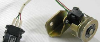
How to replace a Hall sensor on a car
Since repairing a faulty DC is impractical, we prepare the tools and begin to replace it. You will need:
- screwdriver;
- pliers;
- hammer;
- key “13”.
We proceed according to this scheme:
- We turn off the engine and open the hood.
- Disconnect the pipe from the vacuum regulator.
- Remove the distributor cover.
- Disconnect the connector on the DH.
- We unscrew the holder plate with the “13” key. After this, you can remove the distributor.
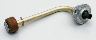
- Take a hammer and use it to knock out the spring clutch screw.
- Remove the screws securing the vacuum regulator. We pull it out - access to the household is open.
- Using a screwdriver, unscrew the screws securing it and remove the mechanism. We replace it with a new one.
Assembly is done in reverse. After completing the procedure, be sure to drive the car to make sure everything was done correctly.
Hall sensor with electric scooter.