Lada Vesta. INTERIOR LIGHTING
Description of the functions of the interior lighting unit 1 – area where the microphone of the in-vehicle emergency call system is located;
2 – area where the in-vehicle emergency call system loudspeaker is located;
3 – emergency call key for the in-vehicle emergency call system;
4 – status indicator of the in-vehicle emergency call system;
5 – indicator of the front passenger seat belt not fastened;
6 – indicator of the disabled front passenger airbag;
7 – key for turning the general interior lighting section into “on” mode;
8 – key for turning on the general interior lighting section in the “on when the door is open” mode;
9 – key for turning on individual lighting of the driver’s seat;
10 – key for turning on the individual lighting of the front passenger seat;
11- section of individual lighting of the driver’s seat;
12 – section for individual lighting of the front passenger seat;
13 – general lighting section.
The interior lighting unit performs the functions of general interior lighting, illumination of the driver's and front passenger's seats, as well as communication functions with the operator of the ERA GLONASS system.
When you press the icon key, the general lighting mode is turned on. When you press a key with an icon, the “on when the door is open” mode is activated. If both keys are pressed, the key has priority
with pictogram
Each section of individual lighting is activated by a corresponding key with an icon for the driver
or for the front passenger.
Switching operating modes of individual lighting occurs by pressing the corresponding key again.
Signaling devices and indicators as part of BOS
– front passenger airbag deactivated indicator, signal color yellow.
– warning light for the front passenger seat belt not fastened, the color of the signal is red.
ψ – red in-vehicle emergency call system status indicator. Lights up for 5 seconds each time the ignition is turned on, and then goes out. The indicator also lights up if there is a malfunction in the in-vehicle emergency call system.
Emergency call system
Your vehicle is equipped with an in-vehicle emergency call system (hereinafter referred to as SVES), designed to automatically (in case of an accident) and manually call an operator of the ERA GLONASS system. A microphone and loudspeaker are used to communicate with the operator of the ERA GLONASS system.
SOS – the key to call the operator of the “ERA GLO-NASS” system is located in the interior lighting unit. Push-button switch with non-fixed “on” position. The key press time to initiate an emergency call is 2 seconds.
In standby mode (with the ignition on), SVEOS carries out self-diagnosis, receives signals from the GLONASS and GPS navigation satellite systems, and constantly calculates the time, speed, direction of movement and coordinates of the vehicle's location.
In a variant version, the car is equipped with an interior lighting unit without the function of the ERA GLONASS telecommunications system.
Automatic emergency call
In the event of a road traffic accident (RTA), if the airbags are deployed, SVEOS generates a minimum set of data containing information about the coordinates and parameters of the vehicle at the time of the accident, the time of the accident, the VIN code of the vehicle and other information necessary for emergency response , and transfers it to the operator of the ERA GLONASS system. After transmitting the minimum set of data, the operator is dialed for voice communication. While making a call to the operator,
The SOS key light flashes red. When transmitting a minimum set of data and during voice communication with the operator, the backlight of the “SOS” key lights up continuously in red.
When making voice communication, SVEOS turns off the sound reproduction of the standard (or additionally installed) radio receiver (multimedia system, radio), if sound reproduction was made before the emergency call was made.
SVEOS makes an automatic emergency call only when the ignition is on.
Manual emergency call (SOS key).
A manual call can be made with the ignition on, as well as with the ignition off, if less than 72 hours have passed since the ignition was turned off. To make an emergency call manually, press the “SOS” button on the interior lighting unit and hold it pressed for at least 2 seconds. The operating algorithm of the SVEOS for a manual emergency call is similar to the algorithm described above for an automatic emergency call.
During a call (while the SOS button is flashing red) initiated by pressing the SOS button, if you press the SOS button again and hold for at least 2 seconds, the emergency call will be canceled (the SOS button is illuminated in red will be turned off).
The SVEOS is in this mode if no emergency call is made, if the ignition is turned off and at least 72 hours have passed since the ignition was turned off. In the “Off” mode, the “SOS” button is not backlit, and the system status indicator ψ does not light up. In the “Off” mode, the SVEOS does not respond to pressing the “SOS” button. The SVEOS exits the “Off” mode when the ignition is turned on.
The testing mode is intended to check the functionality of the SVEOS components. In the testing mode, the functionality of the SVEOS status indicator, the microphone and loudspeaker in the interior lighting unit, the backup battery and other internal components of the SVEOS are checked. If you wish, you can independently check the performance of the SVEOS by running the test mode. To start testing mode you must:
– make sure that the engine is turned off;
– turn the key in the ignition switch (33) to the “Ignition on” position and wait 1 minute;
– from the “Ignition on” position, switch 6 times 33 between the “Ignition on” and “+ACC” positions according to the algorithm described below for no more than 5 seconds:
Starting position 33
Action to be performed
End position 33
included
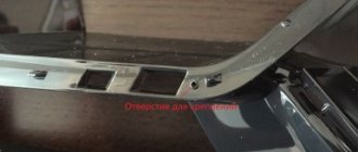
Checklist for installing a lampshade
- Take the necessary measurements;
- Using the obtained parameters, cut out a stencil from available materials (paper, cardboard);
- Disassemble the lampshade, mark the recesses for the bolts on the model;
- On the ceiling of the cabin, select the place where you would like to install the lamp;
- Fix the stencil on the ceiling where the lamp will be installed with adhesive tape;
- Trace the outlines;
- Attach the lamp, make sure the parameters match;
- You need to cut the sheathing with a tool with a very sharp blade to eliminate uneven, torn edges;
- After cutting, reattach the lampshade and correct the contours;
- Where the screws will be screwed in, attach metal clamps;
- Secure the lampshade.
You can connect the device to a car radio, a standard lighting fixture, or a luggage compartment lamp.
Interior lighting
LED lighting of the Lada's interior is represented by lighting in the recess on the front panel, lighting of the driver's foot area and the passenger sitting next to the driver. A special feature of the backlight is its operating mode in light-music mode.
Standard interior lighting is represented by a lampshade, which is located at the top, above the front panel. There are five control keys on the lampshade. With their help, you can turn on the lights on the driver's, passenger's side and fully turn on, turn off, and set the backlight mode when opening the car doors. In addition, the car is equipped with lighting fixtures at the bottom of the door for the driver and the passenger sitting next to him. The backlight lights up every time the door is opened.
Connecting interior lighting
If the Lada Vesta model is not equipped with LED lighting in the niche on the control panel, the car owner can easily install it himself.
To do this you will need wires, a plastic corner, double-sided adhesive tape, and LEDs.
Algorithm of actions
Secure the LED to the plastic corner using double-sided adhesive tape. Secure the corner into the recess on the front panel so that the LED faces the cigarette lighter. Remove the side cover of the recess in the center. To do this, just unscrew one mounting bolt. Connect the LED to the cigarette lighter socket. To replace or install a new interior lamp, first remove the old lamp, then install a new one in its place. The algorithm of actions is identical to the algorithm for installing the lamp in the rear part of the cabin. No additional measurements or stencil making are required.
Removing the dashboard, its parts, instrument panel (frame, trim)
The instrument panel frame is the basic part of the instrument panel that carries ergonomic and decorative functions, on which controls and monitoring of vehicle systems and comfort elements are mounted.
The instrument panel frame is installed on the instrument panel cross member and secured to it with screws.
Place the car in the workplace. disconnect the “ground” terminal from the battery (key “10”).
Remove the wind window pillar trim and the front floor tunnel trim (see here).
Remove the steering shaft housings, disconnect the steering shaft from the instrument panel cross member, and lower the shaft to the floor of the cabin (see here).
Unscrew the screws 3, Figure 15-1, securing the dashboard 1 of the instrument panel, remove the shield (Torx T20 head).
Unscrew screws 4 securing the 2 instrument cluster, remove the instrument cluster by disconnecting the instrument panel wiring harness block from it (Torx head T20, extension).
Figure 15-1 — Fastening the panel and instrument panel combination: 1 — instrument panel panel; 2 — instrument cluster; 3 — screw securing the instrument panel; 4 — screw for securing the instrument cluster
Remove the left side and center trim of the instrument panel by disconnecting the instrument panel wiring harness connector from the hazard warning switch (flat-head screwdriver).
Unscrew screws 2, Figure 15-2, securing the central deflector 1 of the instrument panel (Torx T20 head).
Figure 15-2 — Attaching the central deflector of the instrument panel: 1 — deflector; 2 - screw for securing the multimedia system
Unscrew screws 2, Figure 15-3, securing player 1 of the multimedia system, remove the player from the instrument panel by disconnecting the cables and connectors of the instrument panel wiring harness from the player (Torx T20 head).
Figure 15-3 — Mounting the multimedia system player: 1 — multimedia system player; 2 — screw for securing the player
Open the glove box lid, remove the glove compartment lighting lamp from the mounting hole, disconnect the instrument panel wiring harness block from the lamp lamp (flat-head screwdriver).
Unscrew the five screws 2, Figure 15-4, securing the glove box 1 to the instrument panel 3, remove the glove box (Torx 20 head).
Figure 15-4 — Fastening the glove box: 1 — glove box; 2 — glove box fastening screw; 3 - instrument panel
Remove the right side trim of the instrument panel by disconnecting the instrument panel wiring harness block from the airbag switch located on the trim.
Figure 15-5 — Instrument panel frame: 1 — screw for securing the instrument panel frame (15 pcs.)
Unscrew fifteen screws 1, Figure 15-5, securing the instrument panel frame to the instrument panel cross member, remove the instrument panel frame from the cross member, remove it from the car interior (Torx 20 head).
Install the instrument panel in the reverse order of removal.
Video
Source
Front panel illumination
The front panel backlight is activated when external lighting devices are turned on. Car owners note that they experience some inconvenience when reading indicators when exposed to direct sunlight. Car owners are trying to independently improve the LED lighting of Lada instruments. Car enthusiasts should take into account that any intervention, modification or improvement of lighting fixtures will result in loss of warranty coverage. If the owner nevertheless decides to improve the lighting, it is necessary to adhere to the algorithm of actions.
Sequence of events
Remove the glove container. To do this, open it and press out the latches that hold the lid. Apply a little force, pull the cover towards you, it will come off. Remove the glove box light. Using a small screwdriver, press out the lamp and disconnect the wires. Unscrew the five bolts and remove the glove compartment. To improve lighting, purchase two 600 V LEDs. Unscrew the hook and screw securing the body of the pulp and paper machine. In connector c1 you need to cut the dark blue wire. In connector c2, strip the blue-red wires. Connect two diodes. In the received kit, connect the dark blue wire to the end of the wire of the same color in connector C1. The green wire is connected to the end of the dark blue wire, which is located inside the harness. The red wire is connected to the end of the blue-red wire in connector c2. Next, the steps are performed in reverse order. If all steps are followed, the panel illumination will be improved. Switching on will be done by turning the ignition key.
Foot light
If there is no lighting in this area, the driver of the car will be able to install the lighting for the feet independently, if he deems it necessary. To perform such a procedure does not require large expenses. The driver will only need a piece of LED strip. Before purchasing a strip, decide what color and power of light you want.
Stages of implementation
Divide the profile into four parts. Each of them is approximately 25-35 cm in diameter. Degrease the surface of the profile. Attach the LED strip to the parts (use available means - glue, adhesive double-sided tape). Connect the LEDs to the standard lighting lamp, or central lighting unit. If you want to install backlighting for the rear row of seats, it is better to place LEDs under the driver’s and front passenger’s seats.
Room lighting
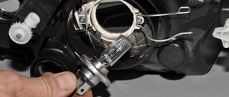
Lighting for the Lada Vesta number is provided by two light bulbs. Lamps often burn out, so drivers must be able to fix this problem themselves and replace the lamps.
The procedure is not complicated and does not require special skills or abilities.
Sequence of events
Use a sharp object to pry the lid of the lantern. Take it out. Remove the lamp and install a new one in its place. A 5V light bulb is built into the lantern. Reinstall the flashlight in reverse order. When removing the flashlight, pry it with a sharp object from the left side.
Why doesn't the light in the cabin turn off?
This problem is also associated with sensors on the doors; it most often appears in the cold season, when the rubber hardens. In this position, the limit switch sticks and the system “thinks” that the doors are open, and the light in the cabin does not go out.
Way to solve the problem
There are two fairly simple options for dealing with this situation:
- Install an additional spring under the rubber band, which will act on the stiff boot.
- Purchase an alternative Hans Pries 104 035 756 sensor. All you need from it is the rubber band itself, which must be replaced in place of the old one. On analogues this part is softer and more elastic.
Installation of rear seat lighting Lada Vesta
To illuminate the rear passengers, you can use an LED strip, which is placed on a pipe under the front row of seats. The neon glow from below will turn on every time the doors are opened. The LEDs are connected to the standard lighting lamp, to the cigarette lighter socket.
For this purpose, the rear courtesy light is used. Installation rules and sequence of events have already been described earlier.
Does the alarm on your Lada Vesta go off randomly? Is the interior light on or does it not turn off at all? The information below may be useful...
| Door opening sensor Lada Vesta! |
Hello, dear visitor! Surely you also had a chance to see on the roads the new product of the Russian automobile industry LADA VESTA, which displays the features of the best models of Ford, Lexus and Renault. Without a doubt, this is another worthy representative of the budget car line and a direct competitor to Volkswagen Polo, Hyundai Solaris, Kia Rio and Skoda Rapid. Maybe this time the Russian car enthusiast will be shocked by the news that LADA VESTA is the car of the year 2016, and AvtoVAZ will finally wipe the nose of the cocky BRIDES.
Why are the lights not on in the Vesta cabin?
In addition to the lack of standard lighting for the rear row (except for the “Lux” configuration), the domestic car has several unpleasant features. One of them manifests itself as follows: the light in the Lada Vesta’s interior does not turn on, regardless of the position of the lighting keys.
This is due to the limit switch located in the doors - the rubber that protects it has different hardness and in some places may not reach the sensor.
It is a misconception that the fuses may blow and therefore the lighting does not work - it is powered directly from the TsKBE.
Way to solve the problem
On a Lada Vesta, when the interior light is not on, do the following:
- Remove the boot from the end cap. A simple option, but you just need to know that if dirt gets in, the sensor may again incorrectly read the door position.
- Replace the limit switch itself if, even with the rubber band removed and the surface clean, the problem with the light remains. Just pull it out, disconnect the terminal and connect a new one.
The owner can do all this independently.
Photo source: https://www.drive2.com/l/496319000096014965
How to replace the door opening sensor on a Lada Vesta:
Thank you very much for the article! A friend had the exact same problem with the sensor on the front passenger door. When the door opened, the light in the cabin did not turn on immediately, because... The elastic band (boot) was too hard. Trimming the boot from the inside did not solve the problem. We didn’t find the boot separately and bought a new end switch assembly for a cosmic sum of 100 rubles.
If anyone needs it, I have the Lada Vesta Technological Maintenance and Repair Instructions! Ask in the comments who needs it I’ll send it to you.
Good afternoon I need instructions. If you don't mind, send it to the address
Dmitry, the instructions for technological maintenance and repair of the Lada Vesta weigh a lot. You can download from the link from the cloud mail: https://cloud.mail.ru/public/Ei4W/nRigLxdBc
Is it possible to see the same instructions for SW Cross?
At -25, all my end caps stopped working, they probably froze.
Hello, Stepan, you can verify that the sensors are working by squeezing the rubber boot with two fingers across the movement of the sensor, that is, so that the boot lengthens. Indeed, in cold weather the original coarse rubber boots freeze and the sensors do not work. It can only be solved by replacing the boot with one with softer rubber (boots from Viburnum, Logan, etc. are suitable).
Thank you, I’ll have to try it, otherwise I have to constantly move them with my hand to get them to work when the door is opened.
Stepan, it’s better not to move, otherwise you may damage the wiring to the sensor. It’s better to simply press the rubber band with two fingers so that it lengthens along the axis of the door sensor rod.
Designation of light bulbs and sensors
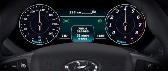
The tachometer is located on the left side of the instrument panel. Inside its scale, starting from the top center, there are eight indicators. If you list them from the top clockwise, it will look like this:
- pedal adjustment;
- seat belt indicator, which will light up if the driver or passenger is not fastened;
- airbag icon;
- backup indicator light, connected when installing additional devices and systems;
- brake failure icon;
- battery charge indicator;
- sign of engine malfunction;
- low oil pressure sign.
Behind the tachometer scale there are four indicators:
- turning on ABS;
- low tire pressure, receives data from tire sensors;
- gearbox malfunctions;
- electric power steering controller.
The speedometer is located in the center. Inside its scale, at the top, there are six indicators:
- trunk open icon;
- open hood indicator;
- alarm indicator;
- open door icon;
- cruise control indicator;
- speed limit icon.
Below the speedometer there is a liquid crystal display displaying the main functions and parameters. There are arrows to the right and left above the display that indicate the turn signals are on.
In the right block of the shield, at the top, there is a coolant temperature scale.
Important: It is prohibited to operate the vehicle if the temperature sensor is faulty.
It is also prohibited to drive a car with an overheated engine. When the 115 degree mark is exceeded, the indicator will remain constantly red and the driver will hear an intermittent beep. Below the scale is the immobilizer icon. Just below are two icons indicating whether the electronic stability control system is on/off. At the bottom of this part there is a fuel level scale in the tank. To the left of which there is an indicator for turning on the reserve fuel volume.
On the right, between these scales, from top to bottom are:
- indicator for turning on dimensions;
- low beam icon;
- front PTF turn-on indicator;
- rear PTF activation icon.