Niva SUV is known as the VAZ-2121
(VAZ 21213, VAZ 21214) and since 2006 as
Lada 4x4
.
Produced from 1977 to the present with various body modifications, mainly 3- and 5-door station wagons with gasoline engines ( carburetor, injection ). In our publication you will find a description of the fuse and relay blocks of the Niva 2121 with their locations, photo examples of execution and block diagrams. Note the fuse responsible for the cigarette lighter. In conclusion, we will offer a Niva electrical diagram for downloading.
Due to the long production period and the huge variety of designs, there is no one general description of the fuse and relay block for Niva 2121. In your car, the purpose of the fuses may differ from those presented.
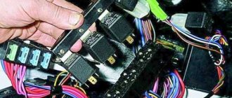
All main fuse and relay boxes are located in the passenger compartment, under the instrument panel on the driver's side.
General arrangement of blocks
Scheme
Description
- Engine control system fuse box
- Windshield wiper relay
- Main fuse box
- Engine Control Relay Box
- Additional relay block (above the gas pedal, and not shown in the diagram)
Mounting blocks for Lada 4×4 2022
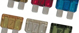
The main and additional units are located in the cabin to the left of the steering wheel, under the instrument panel. The blocks contain fuses of the “Cylinder” size, ten and six fuses, respectively. The ratings and purpose of the fuses are indicated in Table 4 “Circuits protected by fuses”:
Fuse block of standard size “Standard”. The block is located on the left side under the upholstery and contains fuses that are designed to protect engine control system devices. The ratings and purpose of the fuses are shown in Table 5:
The fuse and relay box is located on the left side of the steering column under the instrument panel. The block contains two “Standard” size fuses, which are designed to protect the circuits of the electric fuel pump, electric windows and electric mirrors. The ratings and purpose of the fuses are shown in Table 6:
The fuse and relay box is located on the right side of the steering column under the instrument panel. The block contains one “Maxi” size fuse and two “Standard” size fuses, which are designed to protect the circuits of the hydraulic unit of the anti-lock braking system. The ratings and purpose of the fuses are shown in Table 7:
Attention!
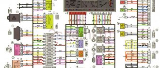
The relay and fuse diagram may differ depending on the configuration and production date of the vehicle. Current diagrams of the mounting block are presented in the operating manual for the date of manufacture of the car (download from the official website for 3-door or 5-door).
Why does a fuse or light relay or any other constantly blow out? Before replacing it with a similar one, you must first find and eliminate the cause of its burnout. This could be a short circuit, incorrectly selected rated current, etc. Use electrical circuit diagrams to troubleshoot problems. Questions on this topic can be asked on the forum.
Engine control system fuse box
Scheme
Designation
| 1 | 15A 1* ECM sensors Starter relay Canister purge valve |
| 1 | 7.5A 2* Controller |
| 1 | 3: Electric fuel pump relay (contacts) Electric fuel pump |
| 1 | 30A 4.5* Cooling fan |
| 2 | 15A 1* Injectors Ignition coils ECM controller Right electric fan relay Left electric fan relay |
| 2 | 15A 2* Electric fuel pump relay (contacts) Electric fuel pump |
| 2 | 30A 3* Reserve |
| 2 | 30A 4.5* Cooling fan |
| 3,4 | 30A 1* Electric fans (right, left) Right electric fan relay Left electric fan relay |
| 3 | 15A 2* Main relay |
| 3 | 15A 3* Controller |
| 3 | 15A 4* Ignition coil, power supply for fan relay control, controller, injectors |
| 3 | 15A 5* Ignition relay |
| 4 | 15A 3* Main relay Electric fan relay (winding) Electric fuel pump relay (winding) Vehicle speed sensor Canister solenoid valve Oxygen sensor Mass air flow sensor Controller |
| 4,5 | 30A 2* Electric fan relay (winding) (right, left) Electric fan motor (right, left) |
| 4 | 15A 4* Mass air flow sensor, phase sensor, heating oxygen sensor (two), canister purge valve, DS |
| 4 | 15A 5* Electric fuel pump |
| 5 | 15A 1* Electric fuel pump Electric fuel pump relay |
1* - 2014-2016, 2* - 2010-2012, 3* - 2007-2008, 4* - Cars with Bosch ME17.9.7/M74 controllers, 5* - Cars with 7.9.7+ controllers.
VAZ 21213 | Electrical faults
Most often, during everyday use of a car, electrical equipment malfunctions occur. For objective reasons, repairs of electrical equipment must be carried out by qualified car service specialists.
If a fuse has blown, replace it; if the same fuse blows again, it serves as a signal to immediately contact a service center.
It is strictly forbidden to replace a blown fuse with another one with a higher “value” or “bug”.
To make troubleshooting easier, purchase a wiring diagram for your vehicle.
If an electrical equipment malfunction occurs before you have time to buy an electrical circuit, you can fix minor problems yourself, which this section will help you with.
Types and arrangement of lamps
Main fuse box
Scheme
Purpose
| 1 | 16A Heater fan electric motor Relay (winding) for headlight wipers and electric motors for headlight wipers in all wipe positions except the initial Relay (winding) for turning on the rear window heating Electric motors for the rear window cleaner and washer Electric motor for the windshield washer |
| 1* | 16A Lamps Horns Socket Lighter Brake light |
| 2 | 8A Relay and electric motor of the windshield wiper Turn signal lamps and relay-interrupter for direction indicators and hazard warning lights (in turn signal mode) Turn signal indicator lamp Tail lights (reversing light lamps) Generator excitation winding (when starting the engine) Differential lock activation indicator lamp in the transfer case Indicator lamp for turning on the parking brake Indicator lamp for the emergency condition of the service brake system Indicator lamp for insufficient oil pressure Fluid temperature indicator in the engine cooling system Fuel level indicator with a warning lamp for fuel reserve Indicator lamp for battery charge Indicator lamp for closing the carburetor air damper Tachometer Electric heater motor Relay headlight cleaners and washer (with the headlight cleaner and washer switch button not pressed) Headlight wiper electric motors in all brush positions except the initial one* |
| 3 | 8A Left headlight (high beam lamp) Indicator lamp for turning on the high beam headlights |
| 4 | 8A Right headlight (high beam lamp) |
| 5 | 8A Left headlight (low beam) |
| 6 | 8A Right headlight (low beam) |
| 7 | 8A Left front light (side light) Right rear light (side light) License plate lights Indicator lamp for turning on side lights |
| 8 | 8A Right front light (side light) Left rear light (side light) Instrument lighting lamp Heater control lever backlighting lamp Cigarette lighter lighting lamp Illumination lamps for switches and switches |
| 9 | 16A Direction indicators and relay-breaker for direction indicators and hazard warning lights Rear window heating element and relay (contacts) for its activation |
| 9* | 8A Warning lamp and oil pressure gauge Coolant temperature gauge Fuel level gauge with reserve warning lamp Parking brake warning lamp Brake fluid level warning lamp Turn indicators and corresponding warning lamp Carburetor choke control warning lamp Battery charge warning lamp Carburetor shut-off valve Tachometer Rear lights (reverse light) Differential lock warning lamp Turn signal relay interrupter Heated rear window (control circuit) |
| 10 | 16A Sound signal Cartridge for connecting a portable lamp Interior lamps Tail lights (brake lamps) |
| 10* | 8A Voltage regulator Generator excitation winding |
| 11 | 8A Turn signal lamps and relay-breaker for turn signals and hazard warning lights (in hazard warning mode) Rear fog lamp |
| 12 | 8A Daytime running light relay, daytime running light lamps |
| 12* | 8A Headlight cleaner and washer relay (with the headlight cleaner and washer switch button pressed) Headlight washer electric motor Headlight cleaner electric motors at the moment of start-up and when the brushes pass the initial position |
| 13 | 8A Rear lights (fog light lamps) Electric motors for headlight cleaners at the time of start-up and when the brushes pass the initial position Relays (contacts) for headlight cleaners Electric motor for headlight washers |
| 14 | 16A Cigarette lighter |
| 15 | 16A Backup Heated rear window (power circuit) |
| 16* | 8A Hazard warning switch and direction indicators in hazard warning mode Rear window wiper and washer |
Fuse number 14 or number 1 at 16A is responsible for the operation of the cigarette lighter, depending on the year of manufacture.
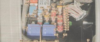
Designation and electrical diagram of the main and additional power supply
The designations and explanations of the fuses of the main and additional units are printed on the surfaces of the covers.
Diagram of the main and additional blocks
Description of the fuses in the upper main section of the VAZ 212214 Niva injector.
| Number on the diagram | Rated current, A | Purpose |
| PR01 | 16 | Heater fan motor, front glass fluid supply system, rear wiper motor |
| PR02 | 8 | Front wiper, direction indicators (with relay), switch block under the steering wheel, instrument cluster instruments and lamps, reverse indicator lamps |
| PR03 | 8 | High beam in the left headlight and high beam indicator lamp in the instrument cluster |
| PR04 | 8 | High beam for right headlight |
| PR05 | 8 | Low beam left |
| PR06 | 8 | Same as on the right |
| PR07 | 8 | Left side dimensions, registration plate illumination, dimensions indication on the instrument cluster |
| PR08 | 8 | Right dimensions and illumination of control devices |
| PR09 | 8 | Hazard warning relay circuit and activation button, rear defogger system |
| PR10 | 8 | Horn, interior lighting and brake lights (all three) |
Overview of the fuses of the small additional block located under the main one.
| Number on the diagram | Rated current, A | Purpose |
| PR11 and 12 | Positions are reserved | To store two 8 amp inserts |
| PR13 | 8 | Turning on the rear fog lamps |
| PR14 | 16 | Cigarette lighter |
| PR15 and 16 | Positions are reserved | For storing two inserts - 16 and 8 amps |
On Niva Urban 4x4 the fuse ratings have been slightly changed. The changed positions are listed below, the remaining chains and denominations remain the same.
| Number on the diagram | Rated current, A | Purpose |
| PR01 | 16 | Heater fan, start of heated rear window, drives for all windshield wipers and washer. Additionally (optional), this insert displays circuits for electric drives of windows and mirrors. |
| PR02 | 8 or 16 | Higher rating - heater fan and compressor (optional change - only for cars with air conditioning) |
| PR09 | 16 | Heated glass (there may be an additional option - heated mirrors) |
| PR10 | 16 | Horn, brake lights and interior lighting |
| PR11 | 8 | Alarm |
| PR12 | 8 | Daytime running light system |
| PR15 | 16 | Heater fan (not on all cars - only with air conditioning) |
The video by Vladimir Zhupikov shows a copy of Niva 21214 Urban with a heater fuse in position PR15.
Engine Control Relay Box
It is located under the main fuse box and consists of 5 relays and 1 fuse.
Scheme
Electrical diagram of the block
Decoding
- Ignition relay
- Main relay
- Right cooling fan relay
- Left cooling fan relay
- Fuel pump relay
- Fuel pump fuse F5 15A
The only difference between Nivas with injection and carburetor systems is due to the fact that the engine control relay unit can be located under the hood of the car in a specially designated compartment.
Video “Replacing fuses on Niva 4x4”
Author Alexander Belousov is looking for the reason for the constant failure of fan fuses on his VAZ 21214.
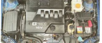
Modern AvtoVAZ SUVs use injection power units. If a malfunction is detected in the electrical equipment of the car, you should first check the serviceability of the fuses and relays. Next, we will show where the mounting block is located (fuse box or black box), as well as the location of the elements inside it.
Additional relay block
This block is located above the gas pedal.
Scheme
Description
- Rear fog lamp relay
- Rear window heating relay
- Low beam relay
- High beam relay
A little higher, above the block, a relay can be installed - a breaker for the turn signals and hazard warning lights.
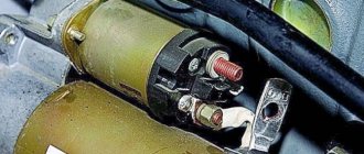
Separate fuses and relays can be installed under the hood: on cars with ABS, on the left side of the engine compartment near the ABS hydraulic unit, a block with fuses is additionally installed that protect the elements of the anti-lock brake system and the starter relay not far from the starter itself.
Replacing the power supply with your own hands
Below we will look at the process of replacing the power supply with your own hands. To replace, you will need a new power supply and a socket head set to “8”.
- First, open the hood and disconnect the battery.
- Now, under the instrument panel, find your power supplies. Using an “8” socket wrench, unscrew the two main nuts.
- Having done this, pry up the power supply and remove them from the studs.
- If you are replacing an old component with a new one, you must mark all the wires before doing so. Or take a new power supply unit and insert the wires from the old unit into it one by one. To remove the idle wires, pull them by their plugs.
- To check the functionality of the new power supply, reconnect the battery.