During the operation of the car, problems may arise that can only be solved after studying the electrical circuits. The article presents detailed wiring diagrams for the Lada 4×4 SUV (VAZ 2121), which will help you not only repair the car, but will also be useful when installing additional electrical equipment, for example, a car alarm, DVR and other accessories..
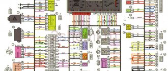
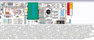
Electrical diagram of VAZ-21213
1 — headlights; 2 — side direction indicators; 3 — electric motor for windshield washer; 4 — headlight washer motor*; 5 - switch; 6 - battery; 7 - starter; 8 - generator; 9 — headlights; 10 — gearmotors for headlight cleaners*; 11 — sound signal; 12 — spark plugs; 13 — carburetor limit switch; 14 — carburetor solenoid valve; 15 — ignition coil; 16 — windshield wiper gearmotor; 17 — carburetor solenoid valve control unit; 18 — ignition distributor sensor; 19 — coolant temperature indicator sensor; 20-oil pressure warning lamp sensor; 21 — plug socket for a portable lamp**; 22 — brake fluid level warning lamp sensor; 23 — windshield wiper relay; 24 — relay for turning on the rear fog light***; 25 — relay for turning on the heated rear window; 26 — relay for turning on headlight cleaners and washer*; 27 — relay for turning on low beam headlights; 28 — relay for turning on the high beam headlights; 29 — ignition relay; 30 — starter activation relay; 31 — relay-breaker for alarm and direction indicators; 32 — heater electric motor; 33 — additional resistor of the heater electric motor; 34 — backlight lamps for heater control levers; 35 — external lighting switch; 36 — main fuse block; 37 — additional fuse block; 38 — reverse light switch; 39 — brake light switch; 40 — instrument lighting regulator; 41 — ignition switch; 42 — three-lever switch; 43 — alarm switch; 44 — tailgate glass cleaner and washer switch*; 45 — heater motor switch; 46 — switch for heating the rear door glass; 47 — rear fog light switch; 48 — lamp switches located in the door pillars; 49 — interior lamps; 50 - cigarette lighter; 51 — switch for the warning lamp for covering the carburetor air damper; 52 — control lamp for covering the carburetor air damper; 53 - switch for differential lock warning lamp; 54 — parking brake warning lamp switch; 55 — sensor for level indicator and fuel reserve; 56 — instrument cluster; 57 — tailgate glass washer motor; 58 — rear lights; 59 — block for connecting additional brake lights; 60 — blocks for connecting side marker indicators; 61 — pads for connecting to the heated glass element of the tailgate; 62 — license plate lights; 63 — gear motor for tailgate glass cleaner.
The order of conditional numbering of plugs in the blocks : a - windshield wipers, headlights and tailgate glass, windshield wiper relay breaker; b — ignition distributor sensor; c — relay-interrupter for alarm and direction indicators; g - switch; d — three-lever switch; e — alarm switch; g — relay for turning on the rear fog light; h — rear lights (numbering of terminals in order from top to bottom); and — instrument clusters.
In the instrument panel wiring harness, the second ends of the white wires are brought together to one point, which is connected to the instrument lighting control. The second ends of the black wires are also brought together to a point connected to ground. The second ends of the yellow wires with a blue stripe are brought together to a point connected to terminal “A” of the main fuse block. And the second ends of the orange wires are also brought together to a point connected to terminal “B” of the main fuse block.
* Installed on parts of manufactured cars; **not installed since 2000; *** installed since 2001. Previously, the rear fog light was switched on directly by switch 47, powered by fuse 3 of the additional fuse box.
Fuses used in the electrical circuit of the Niva 2121 car
Fuses are used to protect almost all electrical circuits in the system.
In the event of a short circuit, they instantly burn out and open the connection, turning off the protected equipment.
The use of fuses on the Niva 2121 car has a number of its own features:
- All electric motors of the gearmotors that control the windshield wipers are reliably protected by fusible inserts that can be reused. They are of the bimetallic type and operate fully automatically;
- to minimize the risk of a short circuit in the equipment circuit, fuses with a wire with a cross-section of 1 mm are used to supply power to the fuel injection system. Such inserts burn out instantly, opening the network and completely eliminating spontaneous combustion;
- circuits of equipment such as a battery, ignition and engine starting systems, and a generator do not need protection, so fuses are not integrated into them at all;
- the power supply system to the electric cooling radiator fan is protected by an insert that can withstand current and more amperes;
- the electric fuel pump, optical equipment, electric fan motor and other high-power consumers are connected to the on-board network through a special relay equipped with its own fuse and do not require any additional protection;
- 15 amp fuses are installed to protect the electrical circuits of the electronic control unit, fuel pump and main relay of the fuel injection system.
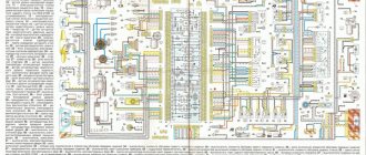
Electrical diagram of VAZ-2121
1 — headlights; 2 — side direction indicators; 3 — headlight washer motor*; 4 - voltage regulator; 5 — battery charge warning lamp relay; 6 - battery; 7 - starter; 8 - generator; 9 — headlights; 10 — gearmotors for headlight cleaners*; 11 — sound signals; 12-spark plugs; 13 — carburetor solenoid valve; 14 — ignition coil; 15 — windshield wiper gearmotor; 16 — coolant temperature indicator sensor; 17 — ignition distributor; 18 — windshield washer electric motor; 19 — oil pressure indicator sensor; 20 — oil pressure warning lamp sensor; 21 — brake fluid level warning lamp sensor; 22 — plug socket for a portable lamp; 23 — relay for turning on headlight cleaners and washer*; 24 — relay for turning on low beam headlights; 25 — relay for turning on the high beam headlights; 26 — windshield wiper relay; 27 — additional fuse block; 28 — main fuse block; 29 — additional resistor of the heater electric motor; 30 — reverse light switch; 31 — brake light switch; 32 — heater electric motor; 33 — relay-interrupter for alarm and direction indicators; 34 — parking brake warning lamp switch; 35 — alarm switch**; 36 — cigarette lighter; 37 — switch for cleaners and headlight washers*; 38 — heater motor switch; 39- external lighting switch; 40 — three-lever switch; 41 — ignition switch; 42 — instrument lighting switch; 43 — lamp switches located in the door pillars; 44 — interior lamps; 45 — oil pressure gauge with insufficient pressure warning lamp; 46 — fuel level indicator with reserve warning lamp; 47 — tachometer; 48 — parking brake warning lamp; 49 — battery charge indicator lamp; 50 — control lamp for the carburetor air damper; 51 — side light indicator lamp; 52 — turn signal indicator lamp; 53 — control lamp for high beam headlights; 54 — speedometer; 55 — carburetor air damper warning lamp switch; 56 — relay-interrupter for the parking brake warning lamp; 57 — coolant temperature indicator; 58 — brake fluid level warning lamp; 59 — differential lock warning lamp; 60 - switch for differential lock warning lamp; 61 — rear lights; 62 — license plate lights; 63-sensor for level indicator and fuel reserve.
The order of conditional numbering of plugs in the blocks : a - windshield and headlight wipers, windshield wiper relay breaker; b — relay-interrupter for alarm and direction indicators; c — three-lever switch; d — hazard warning switch.
* Installed on parts of manufactured cars; ** on cars produced in the 90s, due to the installation of breaker relays 33 without the fifth terminal, the brown wire connecting switch 35 to breaker relay 33 is missing.
Dashboard
For subsequent modifications of the VAZ 2121, the instrument panel was thoroughly redesigned. In particular, the design and location of the warning lamps have changed, and new scales have appeared on the instrument panel indicators.
Conclusions: the owners of the VAZ 2121 car often serviced it themselves. And servicing electrical systems is impossible without original circuit diagrams. This was especially true for modernized versions, where changes were made to the operation scheme of components and assemblies.
Engine control system VAZ-21214
Connection diagram of the VAZ-21214 engine management system with central fuel injection under US-83 toxicity standards with controller 21214-1411010 (EFI-4 type) on VAZ-21214 vehicles : 1 - “CHECK ENGINE” control lamp; 2 — instrument cluster (fragments); 3 — electric fans of the engine cooling system*; 4 — electric heater of the intake pipe; 5 — air temperature sensor; 6 — absolute pressure sensor; 7 — coolant temperature sensor; 8 — block connected to the throttle position sensor; 9 — central fuel injection unit; 10 — block connected to the idle speed regulator; 11 — block connected to the nozzle; 12 — diagnostic block; 13 - controller; 14 — knock sensor; 15 — speed sensor; 16 — oxygen concentration sensor; 17 - adsorber; 18 — battery; 19 - main relay; 20 — fuse block of the engine control system; 21 — relay for turning on the electric fuel pump; 22 — relay for turning on the electric fan*; 23 — relay for turning on the electric heater of the inlet pipe; 24 — electric heater protection fuse; 25 — starter activation relay; 26 — ignition relay; 27 — main car fuse box (fragment); 28 — spark plugs; 29 — tachometer; 30 — electric fuel pump with fuel level sensor; 31 — ignition module; 32 — crankshaft position sensor; 33 - courtesy light switch, located on the driver's door pillar; 34 — control unit of the automobile anti-theft system**; 35 — status indicator of the car anti-theft system**; A - wire going to plug “50” of the ignition switch; B - wire going to plug “15” of the ignition switch; B - wire going to terminal “30” of the generator; G - rear wiring harness wires connected to the fuel level indicator; D - rear wiring harness wire connected to switch 33.
The order of conditional numbering of plugs in blocks : a - controller; b — control unit of the automobile anti-theft system; c — indicator of the state of the automobile anti-theft system; g — speed sensor; d — central fuel injection unit; e — electric fuel pump and oxygen concentration sensor; g — ignition module; h - absolute pressure sensor.
Connection diagram of the VAZ-21214 engine management system with distributed fuel injection under Euro-2 toxicity standards with controller 2123-1411020-10 (type MP 7.0) on VAZ-21214 vehicles : 1 - control lamp of the engine management system; 2 — instrument cluster (fragments); 3 — electric fans of the engine cooling system; 4 — courtesy light switch, located on the driver’s door pillar; 5 — status indicator of the car anti-theft system; 6 — control unit of the automobile anti-theft system; 7-coolant temperature sensor; 8 — air flow sensor; 9 — throttle assembly; 10 — block connected to the throttle position sensor; 11 — block connected to the idle speed regulator; 12 - controller; 13 — oxygen concentration sensor; 14 — knock sensor; 15 — crankshaft position sensor; 16 — speed sensor; 17 - adsorber; 18 — battery; 19 - main relay; 20 — diagnostic block; 21 — fuse block of the engine control system; 22 — relay for turning on the electric fuel pump; 23 — relay for turning on electric fans; 24 — main car fuse box (fragment); 25 — block connected to the additional wiring harness*; 26 — ignition module; 27 - tachometer; 28 — electric fuel pump with fuel level sensor; 29 — nozzles; 30 — spark plugs; A - rear wiring harness wire connected to switch 4; B - wires connected to plug “1” of fuse block 24 (one wire goes to plug “15” of the ignition switch, and the other to plug “85” of the ignition relay); B - rear wiring harness wires connected to the fuel level indicator.
The order of conditional numbering of plugs in blocks : a - controller; b — control unit of the automobile anti-theft system; in - air flow sensor; g — speed sensor; d — indicator of the state of the automobile anti-theft system; e — electric fuel pump and oxygen concentration sensor; g - throttle pipe; h — ignition module.
Electrical connection diagram of the EURO-4 ME17.9.7 ECM for cars of the LADA 4x4 family with engine 21214
:
1 – controller; 2 – diagnostic block; 3 – mass air flow sensor; 4 – coolant temperature sensor; 5 – phase sensor; 6 – electric fuel pump module; 7 – pads for the instrument panel harness and rear harness; 8 – ignition coils; 9 – spark plugs; 10 – electronic accelerator pedal; 11 – throttle pipe with electric drive; 12 – electric fan of the engine cooling system, right; 13 – electric fan of the engine cooling system, left; 14 – knock sensor; 15 – pads for the ignition system harness and injector harness; 16 – nozzles; 17 – solenoid valve for purge of the adsorber; 18 – control oxygen sensor; 19 – diagnostic oxygen sensor; 20 – crankshaft position sensor; 21 – APS control unit; 22 – APS status indicator; 23 – ECM fuse block; 24 – fuse for the power supply circuit of the electric fuel pump; 25 – electric fuel pump relay; 26 – left engine cooling system electric fan relay; 27 – relay for the electric fan of the right engine cooling system; 28 – ignition relay; 29 – pads for the ignition system harness and instrument panel harness; 30 – instrument cluster; 31 – vehicle speed sensor; 32 – brake signal switch; 33 – clutch pedal position signal switch; 34 – main fuse block; 35 – additional relay; 36 – contacts of the instrument panel harness pads and the front harness; 37 – contacts of the instrument panel harness and rear harness pads
Download all schemes in high quality To download files you need to log in to the site
turbomotor412 posted a number of diagrams in his BZ:
Let us remind you that you will find detailed instructions for repairing the Lada 4×4 SUV in this section.
0 0 0 0 0 0
Share on social networks:
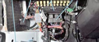
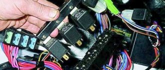
Problems with the generator
The most common malfunction of this unit is brush wear. At the initial stage, it manifests itself as periodic power surges. Symptom: the charging control lamp on the instrument panel blinks periodically - the battery charging indicator lamp, because charging is either there or not.
On a note! Often, brush failure occurs on the fly without any blinking. Yesterday everything worked, today the generator is not breathing.
On a VAZ 2121, the brush block is attached to the generator with one screw and connected to the relay-regulator using knife terminals, the condition of which is also very advisable to check.
In all other Niva car models, the brushes are made in one unit with a relay regulator. Car enthusiasts who consider themselves cool “brewed” call this block “chocolate”.
Remove the back cover of the generator. We disconnect the wires from the brushes (VAZ 2121) and “chocolate” (other models), take out the block and assess the condition of the brushes. They should not be burnt, crumbled at the edges or protrude from the body by less than 5 mm. If something is not right, we change it.
The next problem is wear on the slip rings of the generator rotor. Quite “adult” cars suffer from this disease. Remove the back cover from the generator and carefully inspect the rings.
If they are in bad condition, we replace them. You can see how to replace the slip ring block in the video below.
Replacing the Niva generator rotor slip ring block
The next malfunction is the failure of rectifier or additional diodes. In order to check them, you will have to disconnect all stator windings. They are connected to the diodes using screw lugs.
We unscrew, remove, and test each diode with a multimeter set to diode testing mode. In direct connection, the device should show several hundred Ohms, in reverse - an infinitely large resistance. If this is not the case, change the diodes. Since the semiconductors are pressed into metal plates in the form of a double horseshoe, which are radiators and conductors, you will have to change the entire group of diodes along with the “horseshoe”. Additional diodes can be changed one at a time using a soldering iron.
Expert opinion
Alexey Bartosh
Specialist in repair and maintenance of electrical equipment and industrial electronics.
Ask a Question
To check the diodes, it is enough to disconnect the windings; there is no need to unsolder additional diodes. They will not interfere with the continuity of the rectifier diodes and will themselves ring perfectly.
Well, the last malfunction is a break or breakdown of the stator or rotor windings. We remove the brushes, turn off the windings and check them with an ohmmeter for breaks and short circuits to the housing. In addition to a break and a short to the housing, an interturn short circuit is possible. Without special equipment, it is impossible to detect a short-circuited turn, so you will have to limit yourself to only estimating the resistance and the lack of connection with the generator housing.
In the video below you can see how the field winding is checked using an audio test.
Continuity of the generator excitation winding
Features of the modification
Electrical diagram describing the VAZ 2121 Niva carburetor.
First of all, the changes affected the engine control system and control devices. In particular:
- The wiring diagram for Niva 21213 received an additional wiring harness in the engine compartment for connecting a microcontroller and sensors;
- On the Niva model of recent years of production, a more advanced power unit with the VAZ-21214 index is installed. Instead of a carburetor, it has a fuel frame with injectors from GM. The price of a car with injection has increased because of this;
- The instrument panel has changed - the design is borrowed from the VAZ 2108 model.
Ignition system
The VAZ 21213 engine uses a non-contact ignition system consisting of:
- ignition distributor sensor (marking 3810.3706). It is responsible for creating control pulses supplied to the electronic switch;
- switch (model marking – 3620.3734) in climatic version U2.1 (corresponds to GOST 15150);
- ignition coils (marking 27.3705).
For reference: this device provides increased spark energy, which helps start the engine in cold weather, and also improves the performance of the power unit when operating the vehicle on low-quality fuel.
Dashboard
A modified instrument panel appeared on the car. In particular, instead of a voltmeter, the manufacturer installed a low battery discharge lamp (no. 12 in the diagram).
Tip: if you often operate your car in off-road conditions, you can buy and connect a voltmeter to the instrument panel yourself. It is more informative than a warning light and will allow you to identify electrical system faults long before the battery discharges.
Summarizing
The need to understand the wiring diagram may arise if there are malfunctions in the operation of the system and they need to be eliminated. Of course, complex malfunctions associated with the operation of the generator unit and other devices that are not simple in terms of design will be problematic to solve in a garage without certain knowledge. However, even simple knowledge of the electrical circuit and the ability to decipher the symbols can greatly help the car enthusiast during repairs. In addition, the need to understand wiring may also arise if you decide to upgrade your speakers or install a more advanced audio system.
Review of the composition and location of elements and indicators of the VAZ 2110 instrument panel
The main reference point for driving a car is the dashboard. A serviceable VAZ 2110 instrument panel informs the driver of all the main characteristics of the devices and allows for optimization of control. Each car has its own combination of devices; they can be located completely differently on the dashboard.
Old-style VAZ 2110 instrument panels:
Instrument panel of VAZ 2110 with a mechanical odometer. Article 2110-3801010 VDO instrument panel with one window. Article: 2110-3801010-08 2110-380101-02Schetmash instrument panel with one window. Article: 2110-3801010-05 2110-3801010-06 Instrument panel Automotive instrument with one window. Article: 2110-3801010-04 VDO instrument panel with two windows.
Article: 2115-3801010 2115-3801010-04Schetmash instrument panel with two windows. Article: 2115-3801010-03 2115-3801010-T 2115-3801010-03 Instrument panel Automatic instrument, with 2 windows and zeros before the numbers. Article: 2115-3801010-05 Automatic instrument panel With 2 windows and without zeros in front of the numbers. Article number: 2115-3801010-01 VDO instrument panel (VAZ-21106 with an Opel engine).
Article 21106-3801010
New instrument panels:
VDO instrument panel. Article 1118-3801010 Instrument panel Schetmash. Article: 1118-3801010-12 2170-3801010-01 1118-3801010-13 2170-3801010-03 Instrument panel Auto device. Article: 1118-3801010 1118-3801010-01 1118-3801010-02 541.3801010 2170-3801010-02
Functional
The pinout of this VAZ model is as follows:
- Electronic speedometer;
- Electronic type tachometer;
- Coolant temperature indicator;
- Fuel level indicator in the tank;
- Indicator lamps in the amount of 12 pieces.
Instrument panel diagram
This combination is fixed on a special board, in a separate socket using two screws. The panel is removed after unscrewing them. The accuracy of the board is ensured by the printing method of production and installation of this pinout; foil getinax is used for printing.
Instrument panel pinout
* - on VDO and Schetmash panels with two windows, an external VDO temperature sensor is used, mounted under the bumper. Not used on panels with one window. For panels with a mechanical odometer, this contact receives a signal from terminal “W” of the fuel level sensor (FLS).
Color coding for wiring of old-style panels:
Connecting wires to the VDO panelConnecting wires to the "Schetmash" panel, Kursk Connecting wires to the "AP" panel, Vladimir
The instrument panel is securely attached to the rear of the panel housing and all instruments work efficiently. If the readings of one of the devices are incorrect, repair or replacement of parts should be carried out.
The battery charge indicator light is constantly on.
The phenomenon indicates that the generator has stopped its normal operation; at this moment, the BS is powered by the battery. With a normally charged battery, you have 30-40 km of mileage left to get to the repair site. Disconnect consumers as much as possible, arm yourself with a multimeter and a set of keys.
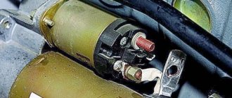
A) Belt break.
Pay attention to the presence of a belt on the pulleys of the water pump and generator. To return it to its place, you will need 17 or 13 socket wrenches, depending on the year of manufacture of the car, as well as a strong flat-head screwdriver.
Disconnect the HF position sensor (for example, on 21213,21214).
Loosen the nuts securing the tension bar and slide it to the side towards the cylinder block.
Place the belt on your seat.
Upon completion of installation, adjust the tension, controlling the deflection when pressing with your thumb on the belt gap between the generator and pump pulleys - 10-15 mm, pump and crankshaft - 12-17 mm. Failure to comply with this requirement may result in the belt slipping with further damage and rupture.
B) Burnout of wires, poor contact in the circuit.
If the circuit opens at terminals B, V and Ш, tighten the nuts or replace the terminals with new ones.
C) The charging relay-voltage regulator has failed.
To initially check the performance of the LV, use a multimeter (voltmeter), which allows you to record the voltage directly at the battery terminals. Normal voltage is considered to be in the range of 13.85±0.35V . If it is different from this, we diagnose the element. The location where the charging relay is located near the Niva is determined by the age of the car. Thus, a remote relay can be found on the right fender liner of a car with a classic engine compartment layout; more modern modifications of generators are equipped with a LV combined with a brush assembly.
The element is not repaired, but replaced completely. To assess the condition, you will need power supplies of 12-14 V, followed by replacement with 16-22 V, and also an incandescent lamp of 1-3 W. According to the diagram drawing, apply current to the voltage regulator in series. If the first test is characterized by the operation of the lamp, and the second - by the absence of glow, then the LV is working.
If there is a break, the lamp will not light up at all, and if there is a breakdown inside the regulator, it will light up even when the voltage increases above 14 V. In addition, weak charging, as well as its absolute absence, is often explained by abrasion of the brushes (residual height less than 5 mm) and slip rings of the generator . If the first part is changed along with the brush holder, then the second is restored by grinding, grooving or removing the remains of the old rings and pressing in new ones. It is recommended to supplement the disassembly of the unit with a total cleaning.
D) Diodes or rectifier unit are faulty
To assess the condition of the mentioned components (negative, positive and additional diodes), arm yourself with a low-power lamp and battery. Diodes are indicated by numbers in the diagram: 1. Positive
conclusions
The modification of the VAZ 21213 Niva undoubtedly benefited him. The new engine and improved ignition system have made its operation even easier and more confident in harsh conditions.
Every modern car today is equipped with an electrical part. The electrical diagram of the VAZ 21214 Niva injector allows, if necessary, to find all the elements included in the on-board network, which is especially important when faults occur in the wiring. Everything a driver needs to know about electrics in domestic SUVs is described in this article.
[Hide]
Battery lost charging reasons
What are the reasons for the charging failure, how to fix the problem on the road or in the garage - this is discussed in this manual.
The electrical circuit of the LADA Niva 4×4 is built according to a classic layout and has undergone virtually no changes since the start of production. Why, knowing its weak points and moving from the obvious to the complex. You will quickly find the root cause. Generator connection principle, drawing:
Basic information about the state of the charger can be obtained from the behavior of the instrument cluster - flashing of the indicator, emergency operation of electrical equipment (headlights, interior lighting, heater) and the engine.
Professional and household electric paint sprayers
In addition to the above classification, electric spray guns can be professional and household. The first type of electric spray gun is designed for use for a long time and painting large surfaces. They are used in industry. A household electric spray gun is usually used for repairs when small amounts of painting are required.
You can’t make an electric spray gun with your own hands, but you can choose a suitable unit in a tool store or online. Let's look at how to choose an electric spray gun for professional or personal use for painting a car. The main characteristics that affect operation are the ability to adjust:
- volume of paint;
- torch shapes;
- piston speed;
- paint spray modes;
- as well as the type of container for the working fluid.
For professional car painting jobs, floor-mounted electric spray guns are often chosen. Some Wagner models are equipped with a laser pointer that estimates the painting distance. It is convenient when the electric spray gun is equipped with a transparent plastic container for working fluid, like Bosch devices.
The units of the German manufacturer Elmos are distinguished by the fact that they supply air constantly, and consumables only when the master pulls the trigger of the gun. This mode allows you to use this tool as a blower to clean various contaminants.